Engine
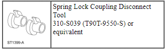
Special Tool(s)
WARNING: Do not smoke, carry lighted tobacco or have an open flame of any type when working on or near any fuel-related component. Highly flammable mixtures are always present and may be ignited. Failure to follow these instructions may result in serious personal injury.
NOTICE: Whenever turbocharger air intake system components are removed, always cover open ports to protect from debris. It is important that no foreign material enter the system. The turbocharger compressor vanes are susceptible to damage from even small particles. All components should be inspected and cleaned, if necessary, prior to installation or reassembly.
- With the vehicle in NEUTRAL, position it on a hoist. For additional information, refer to Section 100-02.
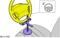
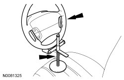
- NOTE: Use a steering wheel holding device (such as Hunter
28-75-1 or equivalent).
Using a suitable holding device, hold the steering wheel in the straight-ahead position.
- Release the fuel system pressure. For additional information, refer to Section 310-00.
- Recover the A/C system. For additional information, refer to Section 412-00.
- Remove the front wheels and tires. For additional information, refer to Section 204-04.
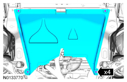
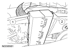
- If equipped, release the 4 retainers and remove the underbody shield.
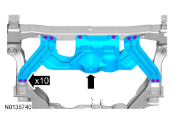
- If equipped, remove the 10 bolts and the skid plate.

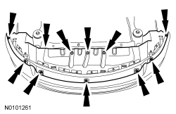
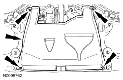
- Remove the 7 bolts, 3 pin-type retainers and the front splash shield.
- Drain the cooling system. For additional information, refer to Section 303-03.
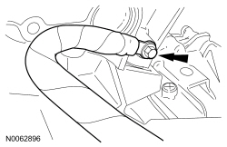
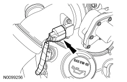
- Disconnect the LH Heated Oxygen Sensor (HO2S) electrical connector.
- Detach the HO2S connector retainer from the bracket.
- Remove the cowl panel grille. For additional information, refer to Section 501-02.
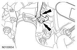
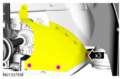
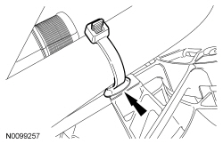
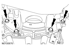
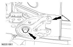
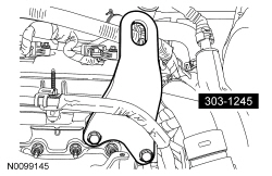
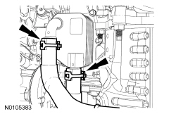
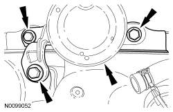
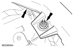
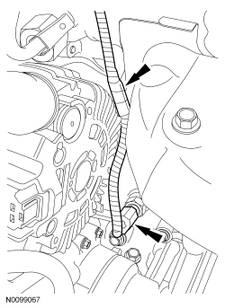
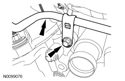
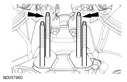
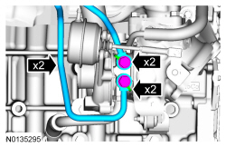
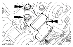
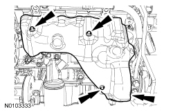
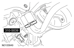
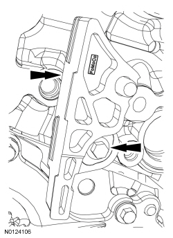
- Detach the 2 brake booster vacuum hose retainers from the strut tower brace.
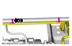
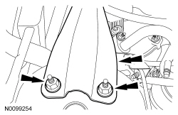
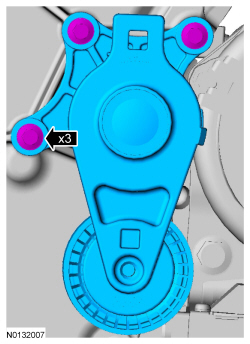
- Remove the 4 nuts (2 shown) and the strut tower brace.

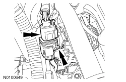
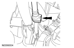
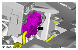
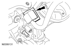
- Disconnect the engine harness electrical connector.

- Disconnect the PCM electrical connector.
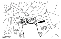
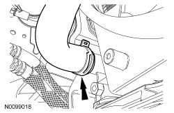
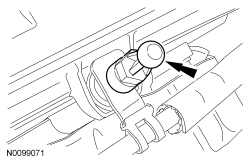
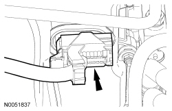
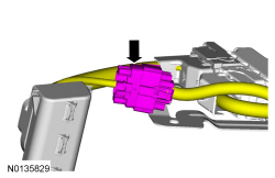
- Remove the engine wiring harness retainer from the bulkhead.
- Push the tab in.
- Slide the wiring harness up and out of the bulkhead.
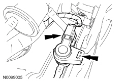
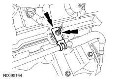
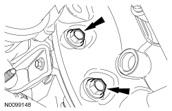
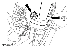
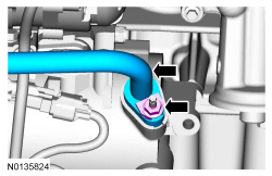
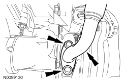
- Remove the nut and disconnect the A/C tube.
- Discard the O-ring seal and gasket seal.

- Remove the nut and the A/C tube.
- Discard the O-ring seal and gasket seal.
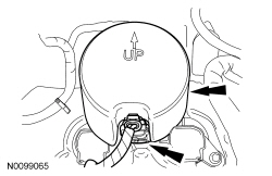
- Remove the degas bottle. For additional information, refer to Section 303-03.
- Remove the engine Air Cleaner (ACL) and ACL outlet pipe. For additional information, refer to Section 303-12.
- If equipped, remove the noise generator. For additional information, refer to Intake Air System Components - Exploded View in Section 303-12.
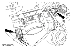
- Disconnect the Turbocharger Boost Pressure (TCBP)/Charge Air Cooler Temperature (CACT) sensor electrical connector.

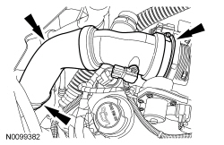
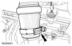
- Loosen the 2 clamps and remove the CAC outlet pipe.
- Remove the battery tray. For additional information, refer to Section 414-01.
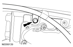
- Remove the bolt and the ground wire.
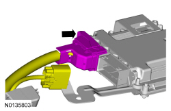
- Disconnect the engine wiring harness electrical connector.

- Remove the nut and disconnect the power feed wire from the positive
battery terminal.
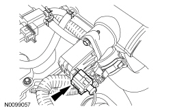
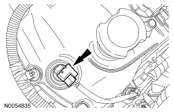
- Disconnect the electrical connector.
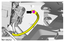
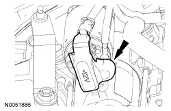
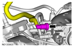
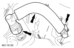
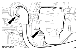
- Disconnect the brake booster vacuum hose quick connect coupling from the intake manifold. For additional information, refer to Section 310-00.

- Disconnect the transaxle control cable from the control lever.
- Disconnect the transaxle control cable from the shift cable bracket.
- Detach the wiring harness pin-type retainer.
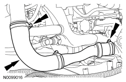
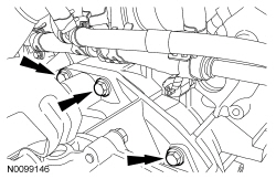
- Loosen the 2 clamps and remove the RH CAC tube.
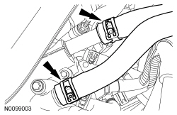
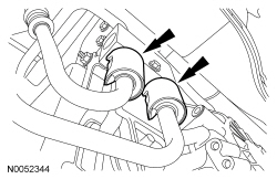
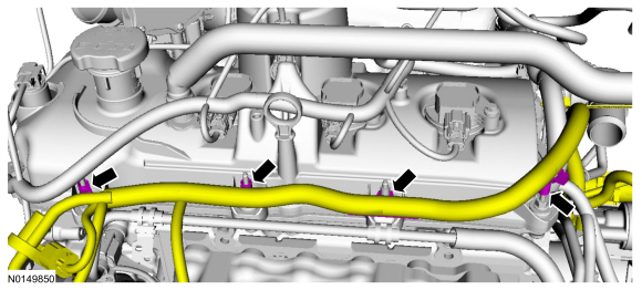
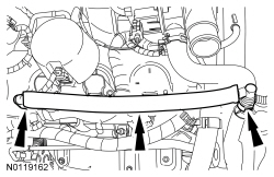
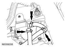
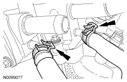
- Disconnect the 2 heater hoses from the intake manifold.
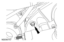
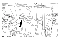
- Remove the bolt and ground wire from the engine front cover.
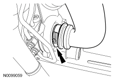
- Disconnect the upper radiator hose from the intake manifold coolant tube.
- If equipped, detach the engine block heater harness from the radiator support wiring harness.
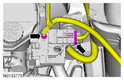
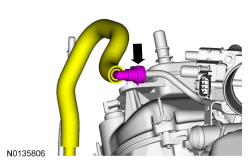
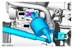
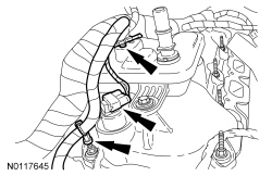
- Disconnect the Evaporative Emission (EVAP) tube quick connect coupling. For additional information, refer to Section 310-00.
- Disconnect the EVAP valve electrical connector and detach the valve from the intake manifold.
- Disconnect the quick connect coupling from the intake manifold and remove the EVAP tube assembly. For additional information, refer to Section 310-00.

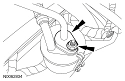
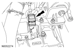
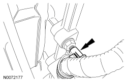
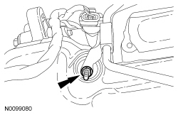
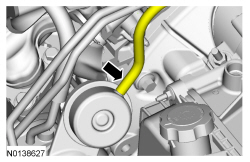
- Disconnect the fuel supply tube from the High-Pressure Fuel Pump (FP) tube. For additional information, refer to Section 310-00.

- Remove the 3 pin-type retainers and position aside.
- Remove the LH and RH catalytic converters. For additional information, refer to Section 309-00.
- NOTICE: Do not allow the intermediate shaft to
rotate while it is disconnected from the gear or damage to the clockspring
may occur. If there is evidence that the intermediate shaft has rotated, the
clockspring must be removed and recentered. For additional information,
refer to Section 501-20B.
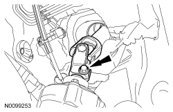
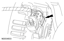
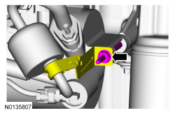
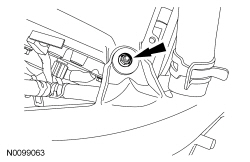
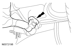
Remove the bolt and disconnect the steering column shaft from the steering gear.
- Discard the bolt.
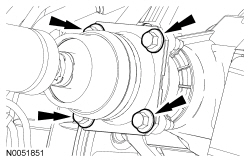
- NOTE: Index-mark the driveshaft for installation.
Remove and discard the 4 bolts and position aside the driveshaft.

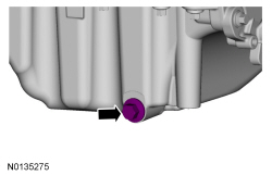
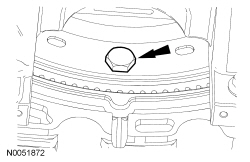
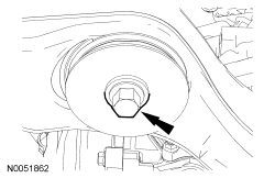
- Remove the drain plug and drain the engine oil.
- Install the drain plug and tighten to 27 Nm (20 lb-ft).
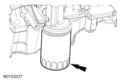
- Remove and discard the engine oil filter.
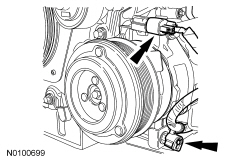
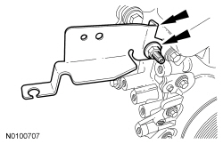
- Remove the A/C tube bracket bolt from the rear of the compressor.

- Remove the nut and disconnect the upper A/C tube from the compressor.
- Discard the O-ring seal and gasket seal.

- Loosen the clamp and disconnect the LH CAC tube from the LH turbocharger.

- Detach the lower radiator hose retainer from the cooling fan and shroud.
- Disconnect the lower radiator hose from the radiator.
- If equipped, disconnect the oil cooler hoses.

- If equipped, unlatch the cooler hose retainer latch and pry up on the oil cooler hose retainer to release the retainer and remove it from the subframe.
- If equipped, disconnect the 2 PTU coolant hoses.
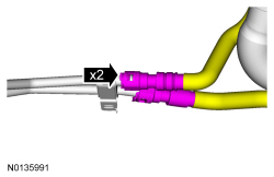
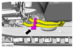
- Remove the 2 secondary latches from the transmission fluid cooler tubes at the transmission fluid cooler thermal bypass valve.
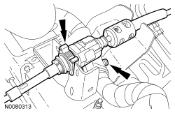
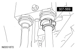
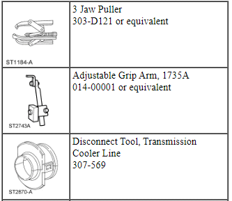
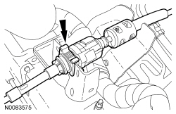
- Using the Transmission Cooler Line Disconnect Tool, disconnect the transmission fluid cooler tubes from the transmission fluid cooler thermal bypass valve.
- Remove the 2 fasteners and the inspection cover.
- Remove and discard the 3 torque converter bolts.
- Remove the 4 oil pan-to-transaxle bolts.
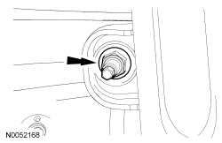
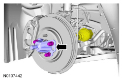
- NOTE: LH shown, RH similar.
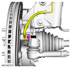
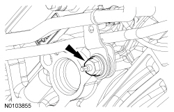
Remove the bolt and the wheel speed sensor.

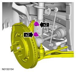
- NOTE: RH shown, LH similar.
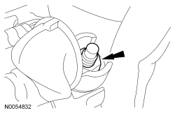
Remove and discard the upper stabilizer link nuts.
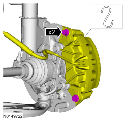
- NOTICE: Do not allow the brake caliper to hang from the brake
flexible hose or damage to the hose may occur.
NOTE: LH shown, RH similar.
Remove the brake caliper guide pin bolts and calipers.- Support the calipers.

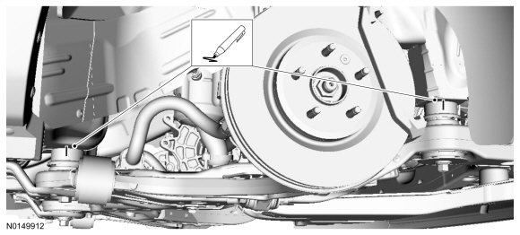
- NOTE: RH shown, LH similar.
Using a wax pencil, mark the relationship of the front and rear subframe to the underbody at the mounting locations on both side.
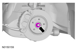
- NOTE: LH shown, RH similar.
Remove the LH and RH halfshaft nuts.
- Do not discard at this time.
- NOTE: LH shown, RH similar.
Separate the LH and RH halfshaft from the wheel hubs.
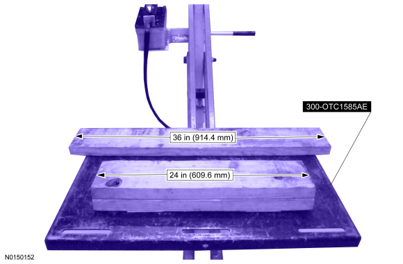
- Position a 2 x 6 board, 36 in (914.4 mm) in length and two 2 x 6 boards
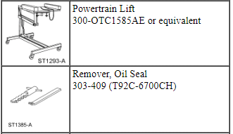
24 in (609.6 mm) in length onto the powertrain lift.
- Position the powertrain lift table with:
- the long board towards the rear of the subframe.
- the short boards under the engine and transmission.
- Position the powertrain lift table with:

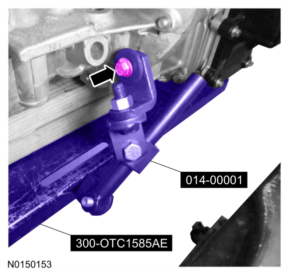
- Install the Adjustable Grip Arm from the powertrain lift table to the LH engine-to-transmission bolt hole.

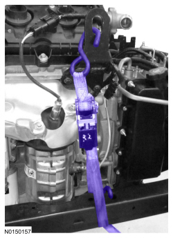
- Install a ratchet strap from the front of the subframe under the powertrain lift table to the rear of the subframe, to secure the subframe to the powertrain lift table.
- NOTE: LH shown, RH similar.
NOTE: The halfshafts are not being remove from the transmission.
Remove the strut-to-wheel knuckle nuts and bolts.- Remove the strut from the wheel knuckle and the halfshafts from the wheel knuckle.
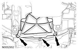
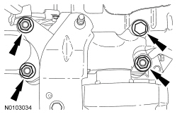
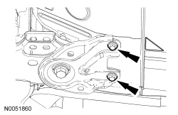
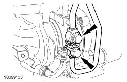
- Remove the 3 nuts and the bolt from the transaxle support insulator bracket-to-transaxle.
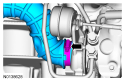
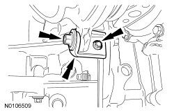
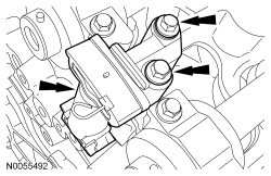
- Remove the 4 engine mount nuts.
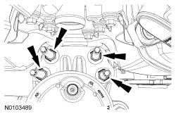
- Remove the 3 bolts and the engine mount.

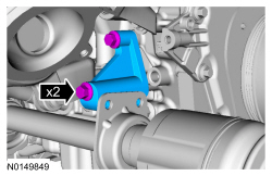
- NOTE: RH shown, LH similar.
Remove the subframe bracket-to-body bolts.

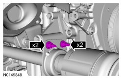
- NOTE: RH shown, LH similar.
Remove the rear subframe bolts and the subframe brackets.
- NOTE: RH shown, LH similar.
Remove the front subframe bolts.

- Lower the subframe and powertrain assembly from the vehicle.
- Remove the engine cover mounting stud from the LH valve cover stud bolt.
- Detach the 4 wiring harness retainer from the valve cover stud bolt.
- Remove the nut and the oil supply tube bracket from the LH valve cover stud bolt.
- Remove the 3 bolts and the LH exhaust manifold heat shield.

- Install the Engine Lift Eye on the LH cylinder head.
- Disconnect the 2 quick connect couplings and remove the crankcase vent tube. For additional information, refer to Section 310-00.
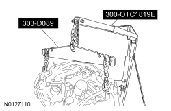
- Install the Heavy Duty Floor Crane and Spreader Bar.

- Install a ratchet strap from the RH knuckle to the subframe to keep the RH halfshaft from coming out of the PTU or transmission.
- Remove the starter motor solenoid cover.
- Remove the 2 nuts and the starter motor wiring terminals.
- Disconnect the wiring harness retainer from the starter motor stud bolt.
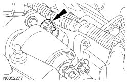
- Remove the bolt, stud bolt and the starter.
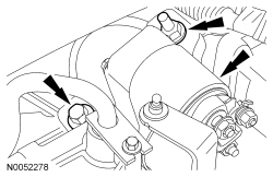
- Remove the 3 bolts and the RH turbocharger lower bracket.
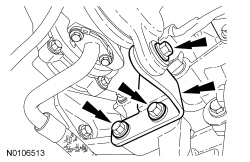
- Remove the 3 bolts and the PTU support bracket.
- Remove the bolt and the ground wire from the RH cylinder head.
- Disconnect the A/C electrical connector and detach the wiring harness retainer.
- Remove the nut and disconnect the generator B+ cable.

- Disconnect the generator electrical connector.
- Disconnect the transaxle control electrical connector.
- Detach the transaxle control wire harness retainer from the transaxle stud bolt.
- Remove the Adjustable Grip Arm.

- Remove the ratchet strap from the front of the subframe under the powertrain lift table to the rear of the subframe.
- NOTE: LH shown, RH similar.
Install the ratchet strap from the front subframe to the LH engine lift eye and from the rear of the subframe to the RH engine lift eye.
- Using the Floor Crane and Spreader Bar, remove the powertrain and
subframe as an assembly from the powertrain lift table and set on the
ground.
- Position wood blocks under the engine and transmission.

- NOTE: LH shown, RH similar.
Remove the ratchet strap from the front subframe to the LH engine lift eye and from the rear of the subframe to the RH engine lift eye.

- Remove the 2 intermediate shaft bracket nuts and the 2 studs.
- Remove the 2 bolts and the RH halfshaft support bracket.
- Remove the 2 LH bottom transaxle-to-engine bolts.
- Remove the LH transaxle-to-engine bolt.
- Remove the 3 transaxle-to-engine bolts.
- Separate the transaxle from the engine.
- Using the Floor Crane and Spreader Bar, remove the engine from the transaxle.
Camshaft
Special Tool(s)
Material
Removal
WARNING: Do not smoke, carry lighted tobacco or have an open flame of any type when working on or near any fuel-related component. Highly flammable mixtures are always present and may be ignited. Failure to follow these instructions may result in serious personal injury.
NOTICE: During engine repair procedures, cleanliness is extremely important. Any foreign material, including any material created while cleaning gasket surfaces, that enters the oil passages, coolant passages or the oil pan may cause engine failure.
NOTICE: Whenever turbocharger air intake system components are removed, always cover open ports to protect from debris. It is important that no foreign material enter the system. The turbocharger compressor vanes are susceptible to damage from even small particles. All components should be inspected and cleaned, if necessary, prior to installation or reassembly.
All camshafts
- With the vehicle in NEUTRAL, position it on a hoist. For additional information, refer to Section 100-02.
- NOTE: Use a steering wheel holding device (such as Hunter
28-75-1 or equivalent).
Using a steering wheel holding device, hold the steering wheel in the straight-ahead position.
- Release the fuel system pressure. For additional information, refer to Section 310-00.
- Recover the A/C system. For additional information, refer to Section 412-00.
- Remove the front wheels and tires. For additional information, refer to Section 204-04.
- If equipped, remove the 4 retainers and the underbody shield.
- If equipped, remove the 10 bolts and the skid plate.
- Remove the 7 bolts, 3 pin-type retainers and the front splash shield.

- Drain the cooling system. For additional information, refer to Section 303-03.
- Disconnect the LH Heated Oxygen Sensor (HO2S) electrical connector.
- Detach the HO2S connector retainer from the bracket.

- Remove the cowl panel grille. For additional information, refer to Section 501-02.
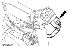
- Detach the 2 brake booster vacuum hose retainers from the strut tower brace.

- Remove the 4 nuts (2 shown) and the strut tower brace.
- Disconnect the engine harness electrical connector.
- Disconnect the PCM electrical connector.

- Remove the engine wiring harness retainer from the bulkhead.
- Push the wiring harness retainer tab in.
- Slide the wiring harness up and out of the bulkhead.

- Remove the nut and disconnect the A/C tube.
- Discard the O-ring seal and gasket seal.
- Remove the nut and the A/C tube.
- Discard the O-ring seal and gasket seal.

- Remove the degas bottle. For additional information, refer to Section 303-03.
- Remove the engine Air Cleaner (ACL) and ACL outlet pipe. For additional information, refer to Section 303-12.
- If equipped, remove the noise generator. For additional information, refer to Intake Air System Components - Exploded View in Section 303-12.
- Disconnect the Turbocharger Boost Pressure (TCBP)/Charge Air Cooler Temperature (CACT) sensor electrical connector.
- Loosen the 2 clamps and remove the CAC outlet pipe.

- Remove the battery tray. For additional information, refer to Section 414-01.
- Remove the bolt and the ground wire.

- Disconnect the engine wiring harness electrical connector.
- Remove the nut and disconnect the power feed wire from the positive
battery terminal.
- Disconnect the electrical connector.

- Disconnect the brake booster vacuum hose quick connect coupling from the intake manifold. For additional information, refer to Section 310-00.
- Disconnect the transaxle control cable from the control lever.

- Disconnect the transaxle control cable from the shift cable bracket.
- Loosen the 2 clamps and remove the RH CAC tube.

- Disconnect the 2 heater hoses from the intake manifold.

- Remove the bolt and ground wire from the engine front cover.

- Disconnect the upper radiator hose from the intake manifold coolant tube.

- If equipped, detach the engine block heater harness from the radiator support wiring harness.
- Disconnect the Evaporative Emission (EVAP) tube quick connect coupling. For additional information, refer to Section 310-00.

- Disconnect the EVAP valve electrical connector and detach from the intake manifold.

- Disconnect the quick connect coupling from the intake manifold and remove the EVAP tube assembly. For additional information, refer to Section 310-00.
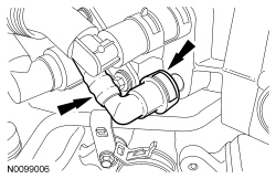
- Disconnect the fuel supply tube. For additional information, refer to Section 310-00.
- Remove the 3 pin-type retainers and position aside.

- Remove the LH and RH catalytic converters. For additional information, refer to Section 309-00.
- NOTICE: Do not allow the intermediate shaft to
rotate while it is disconnected from the gear or damage to the clockspring
may occur. If there is evidence that the intermediate shaft has rotated, the
clockspring must be removed and recentered. For additional information,
refer to Section 501-20B.
Remove the bolt and disconnect the steering column shaft from the steering gear.
- Discard the bolt.

- NOTE: Index-mark the driveshaft for installation.
Remove and discard the 4 bolts and position aside the driveshaft.
- Remove the drain plug and drain the engine oil.
- Install the drain plug and tighten to 27 Nm (20 lb-ft).

- Remove and discard the engine oil filter.

- Remove the A/C tube bracket bolt from the rear of the compressor.
- Remove the nut and disconnect the upper A/C tube from the compressor.
- Discard the O-ring seal and gasket seal.
- Loosen the clamp and disconnect the lower LH CAC tube from the LH turbocharger.

- Detach the lower radiator hose retainer from the cooling fan and shroud.

- Disconnect the lower radiator hose from the radiator.

- If equipped, disconnect the oil cooler hoses.
- If equipped, unlatch the cooler hose retainer latch and pry up on the oil cooler hose retainer to release the retainer and remove it from the subframe.

- If equipped, disconnect the 2 PTU coolant hoses.

- Remove the 2 secondary latches from the transmission fluid cooler tubes at the transmission fluid cooler thermal bypass valve.

- Using the Transmission Cooler Line Disconnect Tool, disconnect the transmission fluid cooler tubes from the transmission fluid cooler thermal bypass valve.

- NOTE: LH shown, RH similar.
Remove the bolt and the wheel speed sensor.
- NOTE: RH shown, LH similar.
Remove and discard the upper stabilizer link nuts.

- NOTICE: Do not allow the brake caliper to hang from the brake
flexible hose or damage to the hose may occur.
NOTE: LH shown, RH similar.
Remove the brake caliper guide pin bolts and calipers.- Support the calipers.
- NOTE: RH shown, LH similar.
Using a wax pencil, mark the relationship of the front and rear subframe to the underbody at the mounting locations on both side.

- NOTE: LH shown, RH similar.
Remove the LH and RH halfshaft nuts.
- Do not discard at this time.

- NOTE: LH shown, RH similar.
Separate the LH and RH halfshaft from the wheel hubs.

- Position a 2 x 6 board, 36 in (914.4 mm) in length and two 2 x 6 boards
24 in (609.6 mm) in length onto the powertrain lift.
- Position the powertrain lift table with:
- the long board towards the rear of the subframe.
- the short boards under the engine and transmission.
- Position the powertrain lift table with:
- Install the Adjustable Grip Arm from the powertrain lift table to the LH engine-to-transmission bolt hole.
- Install a ratchet strap from the front of the subframe under the powertrain lift table to the rear of the subframe, to secure the subframe to the powertrain lift table.
- NOTE: LH shown, RH similar.
NOTE: The halfshafts are not being remove from the transmission.
Remove the strut-to-wheel knuckle nuts and bolts.- Remove the strut from the wheel knuckle and the halfshafts from the wheel knuckle.

- Remove the 3 nuts and the bolt from the transaxle support insulator bracket-to-transaxle.

- Remove the 4 engine mount nuts.

- Remove the 3 bolts and the engine mount.
- NOTE: RH shown, LH similar.
Remove the subframe bracket-to-body bolts.
- NOTE: RH shown, LH similar.
Remove the rear subframe bolts and the subframe brackets.

- NOTE: RH shown, LH similar.
Remove the front subframe bolts.
- Lower the subframe and powertrain assembly from the vehicle.
- Disconnect the 2 quick connect couplings and remove the crankcase vent tube. For additional information, refer to Section 310-00.

- Remove the nut and the A/C tube from the compressor.
- Discard the O-ring seal and gasket seal.
- Disconnect the 2 quick connect couplings and remove the PCV tube. For additional information, refer to Section 310-00.
- Disconnect the LH turbocharger bypass valve electrical connector.
- NOTE: Index-mark the hoses for installation.
Disconnect the turbocharger wastegate regulating valve hoses from the RH CAC tube and turbocharger wastegate regulating valve.
- Loosen the clamp and remove the LH turbocharger intake tube from the LH turbocharger.
- Disconnect the RH turbocharger bypass valve electrical connector.
- Loosen the clamp and remove the RH CAC tube from the RH turbocharger.
- Loosen the clamp and remove the RH turbocharger intake pipe from the RH turbocharger.
- NOTICE: The compression limiter bushing may fall out of the
mounting bracket grommet on the turbocharger intake tube during service.
Make sure the bushing is in place when reinstalling the tube or damage to
the tube may occur.
Remove the nut from the RH valve cover stud bolt for the RH turbocharger intake tube.
- NOTICE: The compression limiter bushing may fall out of the
mounting bracket grommet on the Charge Air Cooler (CAC) tube during service.
Make sure the bushing is in place when reinstalling the tube or damage to
the tube may occur.
Remove the RH CAC tube nut from the intake manifold and remove the RH CAC tube and turbocharger intake tube as an assembly.
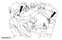
- Remove the noise insulator shield for the fuel injection pump and disconnect the electrical connector.
- Disconnect the Throttle Position (TP) sensor and electronic TB electrical connectors.
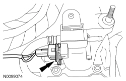
- Disconnect the LH Variable Camshaft Timing (VCT) solenoid electrical connector.
- Disconnect the Engine Oil Pressure (EOP) electrical connector.
- Detach the wiring harness retainer from the block.
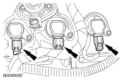
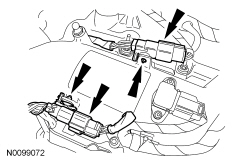
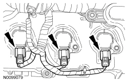
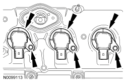
- Disconnect the 3 LH ignition coil-on-plug electrical connectors.
- Remove the lower radiator hose from the thermostat housing.
- Remove the engine cover mounting stud from the LH valve cover stud bolt.

- Detach all the wiring harness retainers from the LH valve cover and stud bolts.
- Remove the nut and the oil supply tube bracket from the LH valve cover stud bolt.

- Remove the oil level indicator.
- Detach and disconnect the 2 fuel injector wiring harness electrical connectors.
- Disconnect the Manifold Absolute Pressure (MAP)/Intake Air Temperature 2 (IAT2) sensor electrical connector.
- Disconnect the turbocharger wastegate regulating valve electrical connector.
- Detach the 2 wire harness-to-intake manifold retainers.
- Remove the fuel tube-to-engine front cover bracket bolt and position the fuel tube aside.
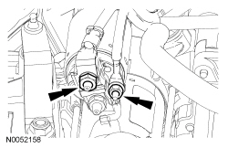
- Disconnect the 2 turbocharger coolant hoses from the intake manifold.
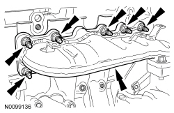
- NOTICE: If the engine is repaired or replaced because of upper
engine failure, typically including valve or piston damage, check the intake
manifold for metal debris. If metal debris is found, install a new intake
manifold. Failure to follow these instructions can result in engine damage.
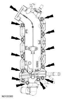
NOTE: Note the routing of the 2 fuel rail wiring harnesses for installation.
Remove the 12 bolts and the intake manifold.- Remove and discard the intake manifold, coolant crossover and thermostat housing gaskets.
- Clean and inspect all sealing surfaces.
- Disconnect the RH VCT solenoid electrical connector and detach the 2 wiring harness retainers.
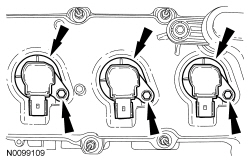
- Disconnect the 3 RH ignition coil-on-plug electrical connectors.
- Detach all the wiring harness retainers from the RH valve cover and stud bolts.
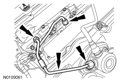
- Remove the nut for the high pressure fuel tube from the LH valve cover stud bolt.
- NOTE: To release the fuel pressure in the high pressure fuel
tube, wrap the flare nuts with a shop towel to absorb any residual fuel
pressure during the loosening of the flare nuts.
Remove the high pressure fuel tube flare nut from the fuel injection pump. Remove the 2 high pressure fuel tube flare nuts from the fuel rails and remove the high pressure fuel tube assembly.
- Remove the 2 bolts and the fuel injection pump.
- Remove the fuel injection pump mounting plate.
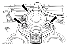
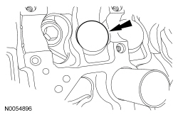
- NOTE: Valve cover is removed for clarity.
Remove the fuel injection pump roller tappet.
- Inspect the fuel injection pump roller tappet. For additional information, refer to Section 303-04B.
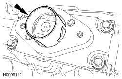
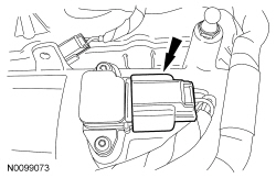
- NOTE: When removing the ignition coil-on-plugs, a slight twisting
motion will break the seal and ease removal.
Remove the 3 bolts and the 3 LH ignition coil-on-plugs.
- NOTE: When removing the ignition coil-on-plugs, a slight twisting
motion will break the seal and ease removal.
Remove the 3 bolts and the 3 RH ignition coil-on-plugs.
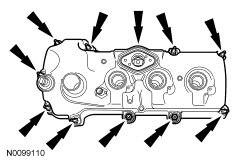
- Loosen the 10 stud bolts and remove the LH valve cover.
- Discard the gasket.
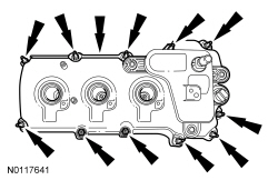
- Loosen the 11 stud bolts and remove the RH valve cover.
- Discard the gasket.
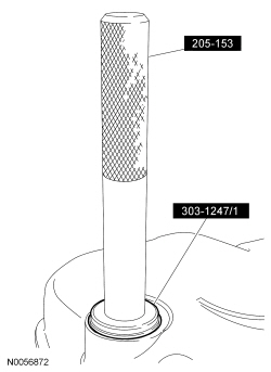
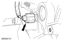
- NOTE: VCT solenoid seal removal shown, spark plug tube seal
removal similar.
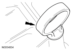
Inspect the VCT solenoid seals and the spark plug tube seals. Install new seals if damaged.
- Using the VCT Spark Plug Tube Seal Remover and Handle, remove the seal(s).
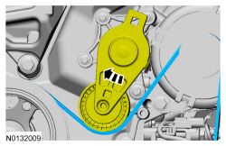
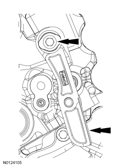
- Rotate the accessory drive belt tensioner clockwise and remove the accessory drive belt.
- Remove the 3 bolts and the accessory drive belt tensioner.
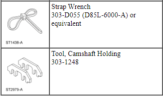
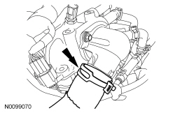
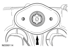
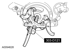
- Using the Strap Wrench, remove the crankshaft pulley bolt and washer.
- Discard the bolt.
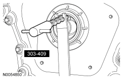
- Using the 3 Jaw Puller, remove the crankshaft pulley.
- Using the Oil Seal Remover, remove and discard the crankshaft front seal.
- Remove the HO2S connector bracket stud bolt from the engine front cover.
- NOTE: Only use hand tools to remove the studs.
Remove the 2 engine mount studs.
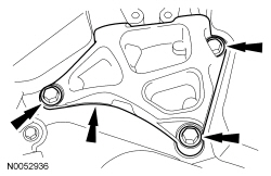
- Remove the 3 bolts and the engine mount bracket.
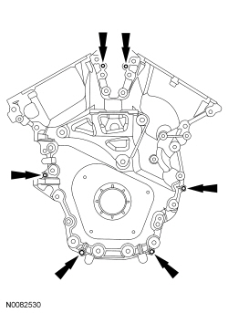
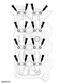
- Remove the 22 engine front cover bolts.
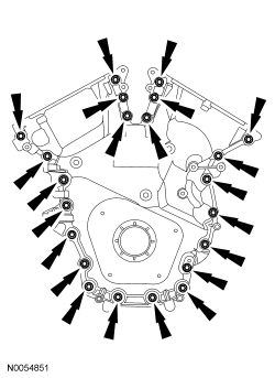
- Install 6 of the engine front cover bolts (finger-tight) into the 6
threaded holes in the engine front cover.
- Tighten the bolts one turn at a time in a crisscross pattern until
the engine front cover-to-cylinder block seal is released.
- Remove the engine front cover.
- Tighten the bolts one turn at a time in a crisscross pattern until
the engine front cover-to-cylinder block seal is released.
- NOTICE: Only use a 3M Roloc Bristle Disk (2-in white, part
number 07528) to clean the engine front cover. Do not use metal scrapers,
wire brushes or any other power abrasive disk to clean the engine front
cover. These tools cause scratches and gouges that make leak paths.
Clean the engine front cover using a 3M Roloc Bristle Disk (2-in white, part number 07528) in a suitable tool turning at the recommended speed of 15,000 rpm.
- Thoroughly wash the engine front cover to remove any foreign material, including any abrasive particles created during the cleaning process.
- NOTICE: Place clean, lint-free shop towels over exposed engine
cavities. Carefully remove the towels so foreign material is not dropped
into the engine. Any foreign material (including any material created while
cleaning gasket surfaces) that enters the oil passages or the oil pan, may
cause engine failure.
NOTICE: Do not use wire brushes, power abrasive discs or 3M Roloc Bristle Disk (2-in white, part number 07528) to clean the sealing surfaces. These tools cause scratches and gouges that make leak paths. They also cause contamination that will cause premature engine failure. Remove all traces of sealant, including any sealant from the inner surface of the cylinder block and cylinder head.
Clean the sealing surfaces of the cylinder heads, the cylinder block and the oil pan in the following sequence.- Remove any large deposits of silicone or gasket material.
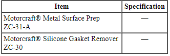
- Apply silicone gasket remover and allow to set for several minutes.
- Remove the silicone gasket remover. A second application of silicone gasket remover may be required if residual traces of silicone or gasket material remain.
- Apply metal surface prep, to remove any remaining traces of oil or coolant and to prepare the surfaces to bond. Do not attempt to make the metal shiny. Some staining of the metal surfaces is normal.
- Make sure the 2 locating dowel pins are seated correctly in the cylinder block.
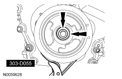
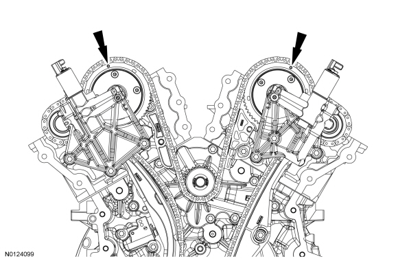
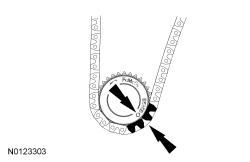
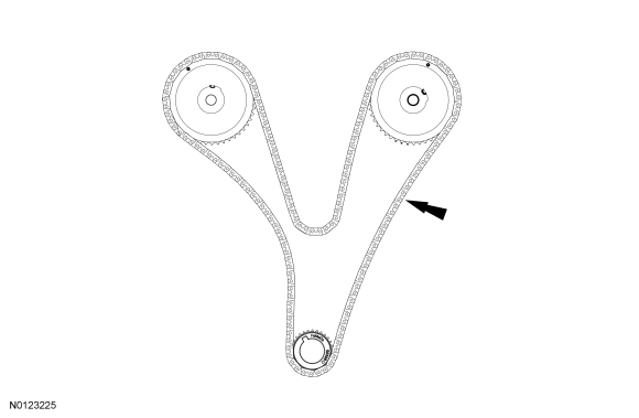
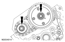
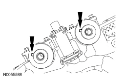
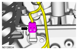
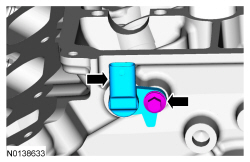
- Rotate the crankshaft clockwise and align the timing marks on the Variable Camshaft Timing (VCT) assemblies as shown.
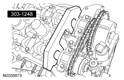
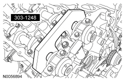
- NOTE: The Camshaft Holding Tool will hold the camshafts in the
Top Dead Center (TDC) position.
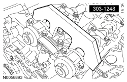
Install the Camshaft Holding Tool onto the flats of the LH camshafts.
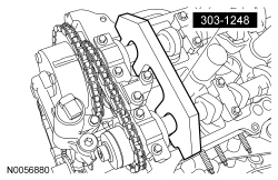
- NOTE: The Camshaft Holding Tool will hold the camshafts in
the TDC position.
Install the Camshaft Holding Tool onto the flats of the RH camshafts.
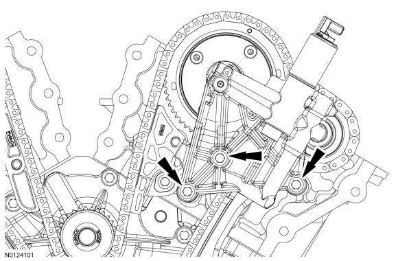
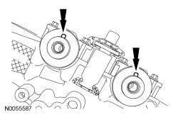
- Remove the 3 bolts and the RH VCT housing.
- Remove the 3 bolts and the LH VCT housing.
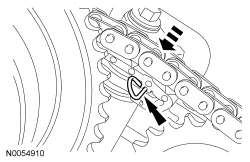
NOTE: The following 3 steps are for primary timing chains when the colored links are not visible.
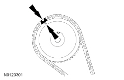
- Mark the timing chain link that aligns with the timing mark on the RH intake VCT assembly as shown.
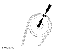
- Mark the timing chain link that aligns with the timing mark on the LH intake VCT assembly as shown.
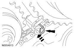
- NOTE: The crankshaft sprocket timing mark should be between the 2
colored links.
Mark the 2 timing chain links that align with the timing mark on the crankshaft sprocket as shown.
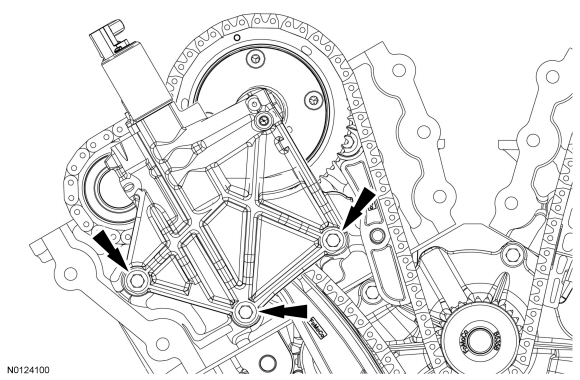
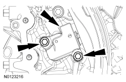
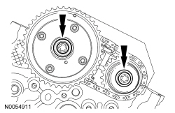
- Remove the 2 bolts and the primary timing chain tensioner.
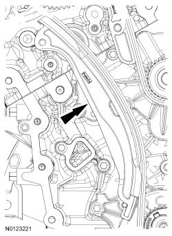
- Remove the primary timing chain tensioner arm.
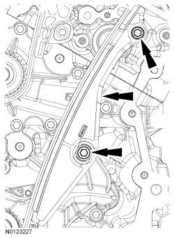
- Remove the 2 bolts and the lower LH primary timing chain guide.
- Remove the primary timing chain.
LH camshafts
- Compress the LH secondary timing chain tensioner and install a suitable lockpin to retain the tensioner in the collapsed position.
- NOTE: The VCT bolt and the exhaust camshaft bolt must be
discarded and new ones installed. However, the exhaust camshaft washer is
reusable.
Remove and discard the LH VCT assembly bolt and the LH exhaust camshaft sprocket bolt.
- Remove the LH VCT assembly, secondary timing chain and the LH exhaust camshaft sprocket as an assembly.
- NOTE: When the Camshaft Holding Tool is removed, valve spring
pressure will rotate the LH camshafts approximately 3 degrees to a neutral
position.
Remove the Camshaft Holding Tool from the LH camshafts.
- NOTICE: The camshafts must remain in the neutral position
during removal or engine damage may occur.
Verify the LH camshafts are in the neutral position.
- NOTE: Cylinder head camshaft bearing caps are numbered to verify
that they are assembled in their original positions.
Remove the bolts and the LH camshaft bearing caps.
- Remove the LH camshafts.
RH camshafts
- Compress the RH secondary timing chain tensioner and install a suitable lockpin to retain the tensioner in the collapsed position.
- NOTE: The VCT bolt and the exhaust camshaft bolt must be
discarded and new ones installed. However, the exhaust camshaft washer is
reusable.
Remove and discard the RH VCT assembly bolt and the RH exhaust camshaft sprocket bolt.
- Remove the RH VCT assembly, secondary timing chain and the RH exhaust camshaft sprocket as an assembly.
- Remove the Camshaft Holding Tool from the RH camshafts.
- NOTICE: The camshafts must remain in the neutral position
during removal or engine damage may occur.
Rotate the RH camshafts counterclockwise to the neutral position.
- NOTE: Cylinder head camshaft bearing caps are numbered to verify
that they are assembled in their original positions.
Remove the bolts and the RH camshaft bearing caps.
- Remove the RH camshafts.
Valve Tappets
NOTICE: During engine repair procedures, cleanliness is extremely important. Any foreign material, including any material created while cleaning gasket surfaces that enters the oil passages, coolant passages or the oil pan, may cause engine failure.
- Depending on the valve tappets being serviced, remove the LH and/or the RH camshafts. For additional information, refer to Camshaft in this section.
- NOTE: If the components are to be reinstalled, they must be
installed in the same positions. Mark the components for installation into
their original locations.
Remove the valve tappets from the cylinder head.
Valve Spring, Retainer and Seal
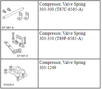
Special Tool(s)
NOTICE: During engine repair procedures, cleanliness is extremely important. Any foreign material, including any material created while cleaning gasket surfaces that enters the oil passages, coolant passages or the oil pan, may cause engine failure.
- Remove the valve tappets from the cylinder being serviced. For additional information, refer to Valve Tappets in this section.
- Rotate the crankshaft until the piston for the valve being serviced is at the top of its stroke.
- NOTICE: If air pressure has forced the piston to the bottom of
the cylinder, any loss of air pressure will allow the valve to fall into the
cylinder. If air pressure must be removed, support the valve prior to
removal or engine damage may occur.
NOTE: If the components are to be reinstalled, they must be installed in the same positions. Mark the components for installation into their original locations.
NOTE: If a valve drops into the cylinder, remove the cylinder head. For additional information, refer to Cylinder Head - RH or Cylinder Head - LH in this section.
Pressurize the cylinder using compressed air.
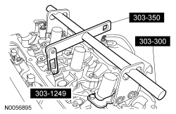
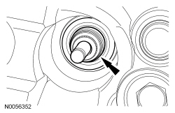
- Using the Valve Spring Compressors, remove the keys, retainer and spring.
- Remove and discard the valve stem seal.
Cylinder Head - RH
Special Tool(s)
Material
NOTICE: During engine repair procedures, cleanliness is extremely important. Any foreign material, including any material created while cleaning gasket surfaces, that enters the oil passages, coolant passages or the oil pan, may cause engine failure.
NOTICE: Whenever turbocharger air intake system components are removed, always cover open ports to protect from debris. It is important that no foreign material enter the system. The turbocharger compressor vanes are susceptible to damage from even small particles. All components should be inspected and cleaned, if necessary, prior to installation or reassembly.
- Remove the fuel rails. For additional information, refer to Section 303-04B.
- Remove the RH camshafts. For additional information, refer to Camshaft in this section.
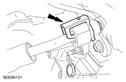
- Disconnect the RH Camshaft Position (CMP) sensor electrical connector.
- Remove the bolt and the RH CMP sensor.
- Remove the bolt and the ground wire.

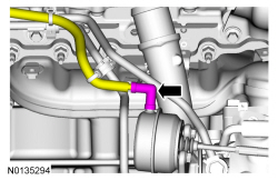
- Disconnect the Cylinder Head Temperature (CHT) sensor electrical connector from the rear of the RH cylinder head.
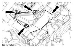
- Remove the 5 bolts and the 2 upper RH exhaust manifold heat shields.
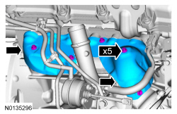
- Disconnect the turbocharger wastegate regulating valve hose from the RH turbocharger assembly.
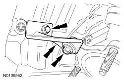
- Remove the 2 bolts and the turbocharger oil return tube from the RH
turbocharger.
- Remove and discard the gasket.
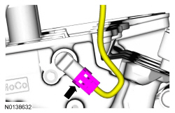
- Remove the oil supply tube secondary latch.
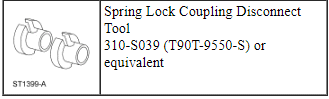
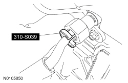
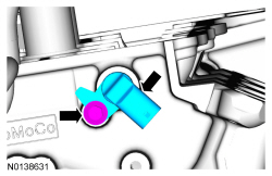
- Using the Spring Lock Coupling Disconnect Tool, remove the RH
turbocharger oil supply tube from the quick connect fitting.
- Inspect and if necessary, replace the quick connect fitting.
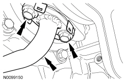
- Remove the 2 coolant tube banjo bolts and the RH turbocharger coolant
tubes and sealing washers.
- Discard the sealing washers.
- Remove the coolant tube bracket-to-cylinder head bolt.
- Remove the 3 bolts and the upper turbocharger-to-cylinder block bracket.
- Remove the 3 exhaust manifold-to-turbocharger bolts and the turbocharger
assembly.
- Discard the gasket and bolts.
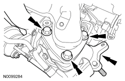
- Remove the RH turbocharger oil supply tube banjo bolt.
- Discard the sealing washer.
- Discard the oil supply tube filter.
- Remove the 8 nuts and the RH exhaust manifold.
- Discard the nuts and exhaust manifold gaskets.
- Clean and inspect the RH exhaust manifold. For additional information, refer to Section 303-00.
- Remove and discard the 8 RH exhaust manifold studs.
- NOTICE: Do not use metal scrapers, wire brushes, power
abrasive discs or other abrasive means to clean the sealing surfaces. These
may cause scratches and gouges resulting in leak paths. Use a plastic
scraper to clean the sealing surfaces.
Clean the exhaust manifold mating surface of the cylinder head with metal surface prep. Follow the directions on the packaging.
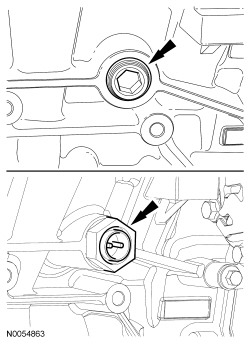
- Remove the LH cylinder block drain plug.
- Allow coolant to drain from the cylinder block.
- If equipped, remove the heat shield and disconnect the block heater
electrical connector.
- Remove the block heater wiring harness from the engine.
- Remove the RH cylinder block drain plug or, if equipped, the block
heater.
- Allow coolant to drain from the cylinder block.
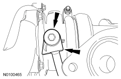
- Remove the bolt and the RH timing chain guide.
- Remove the bolts and the RH secondary timing chain tensioner.
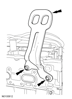
- Remove the 2 bolts and the RH engine lifting eye.
- NOTE: If the components are to be reinstalled, they must be
installed in the same positions. Mark the components for installation into
their original locations.
Remove the valve tappets from the cylinder head.

- Inspect the valve tappets. For additional information, refer to Section 303-00.
- Remove and discard the M6 bolt.
- NOTICE: Place clean, lint-free shop towels over exposed engine
cavities. Carefully remove the towels so foreign material is not dropped
into the engine. Any foreign material (including any material created while
cleaning gasket surfaces) that enters the oil passages or the oil pan, may
cause engine failure.
NOTICE: Aluminum surfaces are soft and may be scratched easily. Never place the cylinder head gasket surface, unprotected, on a bench surface.
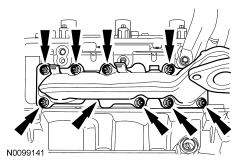
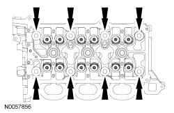
NOTE: The cylinder head bolts must be discarded and new bolts must be installed. They are a torque-to-yield design and cannot be reused.
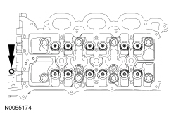
Remove and discard the 8 bolts from the cylinder head.- Remove the cylinder head.
- Discard the cylinder head gasket.
- NOTICE: Do not use metal scrapers, wire brushes, power
abrasive discs or other abrasive means to clean the sealing surfaces. These
tools cause scratches and gouges that make leak paths. Use a plastic
scraping tool to remove all traces of the head gasket.
NOTE: Observe all warnings or cautions and follow all application directions contained on the packaging of the silicone gasket remover and the metal surface prep.
NOTE: If there is no residual gasket material present, metal surface prep can be used to clean and prepare the surfaces.
Clean the cylinder head-to-cylinder block mating surfaces of both the cylinder heads and the cylinder block in the following sequence.- Remove any large deposits of silicone or gasket material with a plastic scraper.
- Apply silicone gasket remover, following package directions, and allow to set for several minutes.
- Remove the silicone gasket remover with a plastic scraper. A second application of silicone gasket remover may be required if residual traces of silicone or gasket material remain.
- Apply metal surface prep, following package directions, to remove any remaining traces of oil or coolant and to prepare the surfaces to bond with the new gasket. Do not attempt to make the metal shiny. Some staining of the metal surfaces is normal.
- Support the cylinder head on a bench with the head gasket side up. Check the cylinder head distortion and the cylinder block distortion. For additional information, refer to Section 303-00.
Cylinder Head - LH
Special Tool(s)
Material
NOTICE: During engine repair procedures, cleanliness is extremely important. Any foreign material, including any material created while cleaning gasket surfaces, that enters the oil passages, coolant passages or the oil pan, may cause engine failure.
NOTICE: Whenever turbocharger air intake system components are removed, always cover open ports to protect from debris. It is important that no foreign material enter the system. The turbocharger compressor vanes are susceptible to damage from even small particles. All components should be inspected and cleaned, if necessary, prior to installation or reassembly.
- Remove the fuel rails. For additional information, refer to Section 303-04B.
- Remove the LH camshafts. For additional information, refer to Camshaft in this section.
- Disconnect the LH Camshaft Position (CMP) sensor electrical connector.
- Remove the bolt and the LH CMP sensor.
- Detach the wiring harness retainer from the rear of the LH cylinder head.
- Remove the coolant tube bracket-to-cylinder head nut.
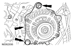
- Remove the nut and disconnect the generator B+ cable.
- Disconnect the generator electrical connector.

- Remove the nut, bolt and the generator.
- Remove the generator stud.
- Remove the 3 bolts and the LH exhaust manifold heat shield.
- Disconnect the turbocharger wastegate regulating valve hose from the LH turbocharger assembly.
- Remove the 2 bolts and the LH turbocharger oil return tube from the
turbocharger.
- Remove and discard the gasket.
- Remove the LH oil supply tube secondary latch.
- Using the Spring Lock Coupling Disconnect Tool, remove the LH oil supply
tube from the quick connect fitting.
- Inspect and if necessary, replace the quick connect fitting.
- Remove the 2 coolant tube banjo bolts and the LH turbocharger coolant
tubes and sealing washers.
- Discard the sealing washers.
- Remove the LH turbocharger oil supply tube banjo bolt.
- Discard the sealing washer.
- Discard the oil supply tube filter.
- Remove the 2 bolts and the lower LH turbocharger-to-cylinder block bracket.
- Remove the 2 bolts and the upper LH turbocharger bracket-to-cylinder block bracket.
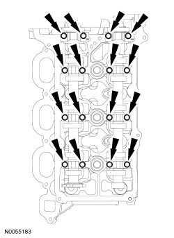
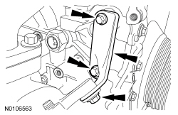
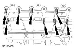
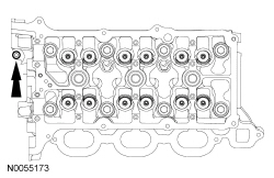
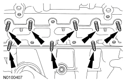
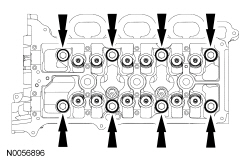
- Remove the 8 LH exhaust manifold nuts (6 shown) and the exhaust manifold
and turbocharger assembly.
- Discard the exhaust manifold gasket and nuts.
- Clean and inspect the LH exhaust manifold. For additional information, refer to Section 303-00.
- Remove and discard the 8 LH exhaust manifold studs.
- NOTICE: Do not use metal scrapers, wire brushes, power
abrasive discs or other abrasive means to clean the sealing surfaces. These
may cause scratches and gouges resulting in leak paths. Use a plastic
scraper to clean the sealing surfaces.
Clean the exhaust manifold mating surface of the cylinder head with metal surface prep. Follow the directions on the packaging.
- Remove the LH cylinder block drain plug.
- Allow coolant to drain from the cylinder block.

- If equipped, remove the heat shield and disconnect the block heater
electrical connector.
- Remove the block heater wiring harness from the engine.

- Remove the RH cylinder block drain plug or, if equipped, the block
heater.
- Allow coolant to drain from the cylinder block.

- Remove the bolt and the upper LH primary timing chain guide.
- Remove the 2 bolts and the LH secondary timing chain tensioner.
- NOTE: If the components are to be reinstalled, they must be
installed in the same positions. Mark the components for installation into
their original locations.
Remove the valve tappets from the cylinder head.

- Inspect the valve tappets. For additional information, refer to Section 303-00.
- Remove and discard the M6 bolt.
- NOTICE: Place clean, lint-free shop towels over exposed engine
cavities. Carefully remove the towels so foreign material is not dropped
into the engine. Any foreign material (including any material created while
cleaning gasket surfaces) that enters the oil passages or the oil pan, may
cause engine failure.
NOTICE: Aluminum surfaces are soft and may be scratched easily. Never place the cylinder head gasket surface, unprotected, on a bench surface.
NOTE: The cylinder head bolts must be discarded and new bolts must be installed. They are a torque-to-yield design and cannot be reused.
Remove and discard the 8 bolts from the cylinder head.- Remove the cylinder head.
- Discard the cylinder head gasket.
- NOTICE: Do not use metal scrapers, wire brushes, power
abrasive discs or other abrasive means to clean the sealing surfaces. These
tools cause scratches and gouges that make leak paths. Use a plastic
scraping tool to remove all traces of the head gasket.
NOTE: Observe all warnings or cautions and follow all application directions contained on the packaging of the silicone gasket remover and the metal surface prep.
NOTE: If there is no residual gasket material present, metal surface prep can be used to clean and prepare the surfaces.
Clean the cylinder head-to-cylinder block mating surfaces of both the cylinder heads and the cylinder block in the following sequence.- Remove any large deposits of silicone or gasket material with a plastic scraper.
- Apply silicone gasket remover, following package directions, and allow to set for several minutes.
- Remove the silicone gasket remover with a plastic scraper. A second application of silicone gasket remover may be required if residual traces of silicone or gasket material remain.
- Apply metal surface prep, following package directions, to remove any remaining traces of oil or coolant and to prepare the surfaces to bond with the new gasket. Do not attempt to make the metal shiny. Some staining of the metal surfaces is normal.
- Support the cylinder head on a bench with the head gasket side up. Check the cylinder head distortion and the cylinder block distortion. For additional information, refer to Section 303-00.
 In-Vehicle Repair
Intake Manifold
Removal
NOTICE: During engine repair procedures, cleanliness is extremely
important. Any foreign material, including any material created while cleaning
gasket surfaces that ent ...
 Disassembly
Engine
Special Tool(s)
Material
WARNING: Do not smoke, carry lighted tobacco or have an open flame of any
type when working on or near any fuel-related component. Highly flammable
mixtures are a ...
Other materials:
Rear Suspension
SPECIFICATIONS
Torque Specifications
a Refer to the procedure in this section.
DESCRIPTION AND OPERATION
Rear Suspension
The rear suspension consists of the following components:
Lower arm(s)
Shock absorber(s)
Spring(s)
Stabilizer bar(s)
Stabilizer bar link(s)
Trailing arm(s)
Toe link( ...
Jacking and Lifting
WARNING: When jacking or lifting the vehicle, block all wheels remaining
on the ground. Set the parking brake if the rear wheels will remain on the
ground. These actions help prevent unintended vehicle movement. Failure to
follow these instructions may result in serious personal injury.
&nb ...
Multifunction Electronic Modules
SPECIFICATIONS
Torque Specifications
DESCRIPTION AND OPERATION
Module Controlled Functions
Component Location
Multifunction Electronic Modules
BCM
RFA module
Overview
The BCM controls the following:
Battery saver function
Brake shift interlock
Delayed accessory function
Dimm ...
