Air Conditioning (A/C) Compressor - 2.0L GTDI
Material
Removal and Installation
NOTICE: If installing a new Air Conditioning (A/C) compressor due to an internal failure of the old unit, either a flushing procedure or system filtering procedure must be carried out to remove contamination from the A/C system. Failure to remove contamination from the A/C system, if present, will result in poor A/C performance and/or damage to the new A/C compressor and other components.
- If A/C flushing equipment is available, carry out flushing of the A/C system prior to installing a new A/C compressor. For additional information, refer to Section 412-00.
- If A/C flushing equipment is not available, carry out filtering of the A/C system after a new A/C compressor has been installed. For additional information, refer to Section 412-00.
- Install a new Thermostatic Expansion Valve (TXV), as directed by the A/C flushing or filtering procedure.
- Install a new receiver/drier as directed by the A/C flushing or filtering procedure.
NOTE: Installation of a new receiver/drier is not required when repairing the A/C system, except when there is physical evidence of contamination from a failed A/C compressor or damage to the receiver/drier. Damage to the receiver/drier includes leaks in the receiver/drier, physical damage to the receiver/drier shell or desiccant, or moisture contamination. Moisture contamination results only from a complete loss of refrigerant and equalization of the refrigerant system pressure with atmospheric pressure for a period longer than one hour. If even a slight amount of positive refrigerant pressure is present in the system before repairs are carried out, the receiver/drier should not be replaced.
NOTE: A new A/C compressor may come equipped with an A/C clutch disc and hub, A/C compressor pulley and A/C clutch field coil already installed. If these components are not pre-installed, it will be necessary to transfer these parts from the old A/C compressor to the new compressor prior to installation of the A/C compressor if suitable for reuse.
- If flushing of the A/C system has not been carried out, recover the refrigerant. For additional information, refer to Section 412-00.
- Remove the A/C compressor belt for additional iformation, refer to Section 303-05.
- Remove the A/C compressor.
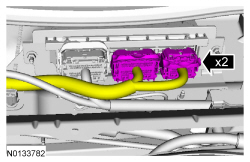
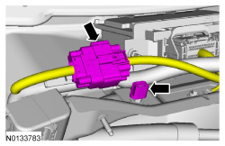
- Detach the wire harness pin-type retainer, disconnect the field coil and control valve electrical connectors.
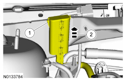
- Remove the A/C compressor suction and discharge fitting nuts and
disconnect the fittings.
- Discard the O-ring seals and gasket seals.
- To install, tighten to 15 Nm (133 lb-in).
- Remove the A/C compressor mounting nut, completely loosen the A/C
compressor mounting stud, remove the A/C compressor bolts and remove the
A/C compressor.
- To Install, tighten A/C compressor mounting stud to 9 Nm (80 lb-in).
- To install, reverse the removal procedure.
- Install new gasket seals and O-ring seals.
- If filtering of the refrigerant system is not to be carried out, add the correct amount of clean PAG oil to the refrigerant system. For additional information, refer to the Refrigerant Oil Adding procedure in Section 412-00.
- If filtering of the refrigerant system is not to be carried out, evacuate, leak test and charge the refrigerant system. For additional information, refer to Section 412-00.
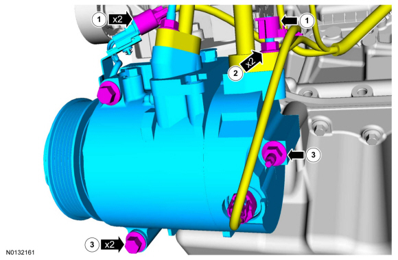
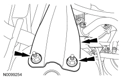
- Tighten the A/C compressor bolts and nut in the sequence shown.
- Tighten to 25 Nm (18 lb-ft).
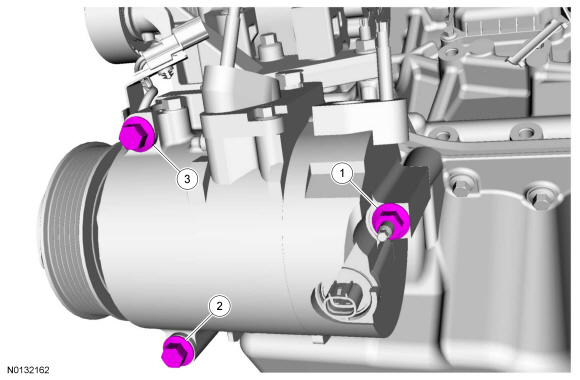
Air Conditioning (A/C) Compressor - 3.5L GTDI, 3.5L Ti-VCT
Material
Removal and Installation
NOTICE: If installing a new Air Conditioning (A/C) compressor due to an internal failure of the old unit, either a flushing procedure or system filtering procedure must be carried out to remove contamination from the A/C system. Failure to remove contamination from the A/C system, if present, will result in poor A/C performance and/or damage to the new A/C compressor and other components.
- If A/C flushing equipment is available, carry out flushing of the A/C system prior to installing a new A/C compressor. For additional information, refer to Section 412-00.
- If A/C flushing equipment is not available, carry out filtering of the A/C system after a new A/C compressor has been installed. For additional information, refer to Section 412-00.
- Install a new Thermostatic Expansion Valve (TXV), as directed by the A/C flushing or filtering procedure.
- Install a new receiver/drier as directed by the A/C flushing or filtering procedure.
NOTE: Installation of a new receiver/drier is not required when repairing the A/C system, except when there is physical evidence of contamination from a failed A/C compressor or damage to the receiver/drier. Damage to the receiver/drier includes leaks in the receiver/drier, physical damage to the receiver/drier shell or desiccant, or moisture contamination. Moisture contamination results only from a complete loss of refrigerant and equalization of the refrigerant system pressure with atmospheric pressure for a period longer than one hour. If even a slight amount of positive refrigerant pressure is present in the system before repairs are carried out, the receiver/drier should not be replaced.
NOTE: A new A/C compressor may come equipped with an A/C clutch disc and hub, A/C compressor pulley and A/C clutch field coil already installed. If these components are not pre-installed, it will be necessary to transfer these parts from the old A/C compressor to the new compressor prior to installation of the A/C compressor if suitable for reuse.
- With the vehicle in NEUTRAL, position it on a hoist. For additional information, refer to Section 100-02.
- If flushing of the A/C system has not been carried out, recover the refrigerant. For additional information, refer to Section 412-00.
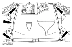
- Remove the lower radiator splash shield.
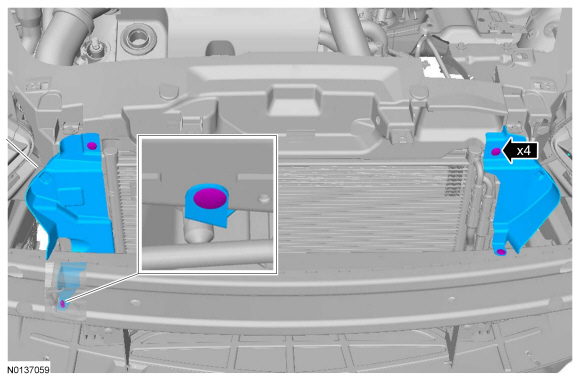
- Remove the 4 underbody shield retainers and the underbody shield (if equipped).

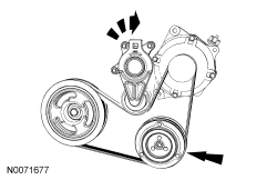
- Release the tensioner and remove the drive belt from the A/C compressor pulley.
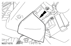
- Remove the 3 A/C compressor splash shield retainers and the splash shield (if equipped).
- Remove the A/C compressor.
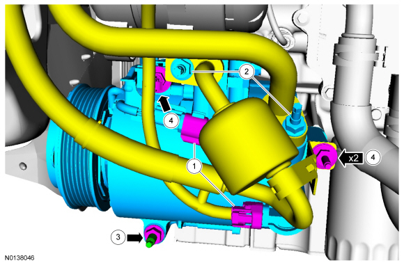
- Disconnect the field coil and control valve electrical connectors.
- Remove the A/C compressor suction and discharge fitting nuts and
disconnect the fittings.
- Discard the O-ring seals and gasket seals.
- To install, tighten to 15 Nm (133 lb-in).
- Remove the lower A/C compressor mounting nut, completely loosen the
A/C compressor mounting stud.
- To install, tighten A/C compressor mounting stud to 9 Nm (80 lb-in).
- To install, tighten A/C compressor nut to 25 Nm (18 lb-ft).
- Detach the pin type retainer, remove the A/C compressor bolts and
remove the A/C compressor.
- To install, tighten to 25 Nm (18 lb-ft).
- To install, reverse the removal procedure.
- Install new gasket seals and O-ring seals.
- If filtering of the refrigerant system is not to be carried out, add the correct amount of clean PAG oil to the refrigerant system. For additional information, refer to the Refrigerant Oil Adding procedure in Section 412-00.
- If filtering of the refrigerant system is not to be carried out, evacuate, leak test and charge the refrigerant system. For additional information, refer to Section 412-00.
Air Inlet Duct
Removal and Installation
- Remove the heater core and evaporator core housing. For additional information, refer to Heater Core And Evaporator Core Housing in this section.
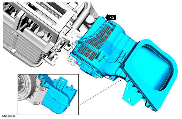
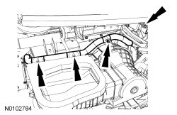
- Remove the air inlet duct.
- Remove the 5 air inlet duct screws.
- To install, reverse the removal procedure.
Blower Motor
Removal and Installation
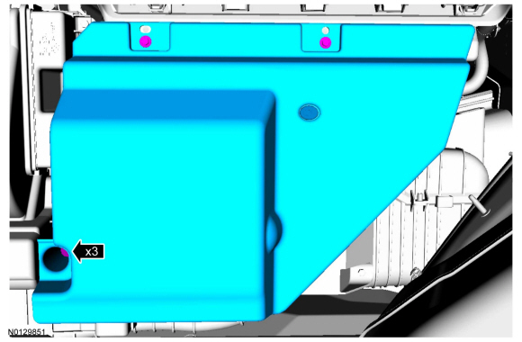
- Remove the 3 RH lower instrument panel insulator screws and the RH lower instrument panel insulator.

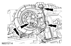
- Remove the blower motor.
- Disconnect the blower motor electrical connector.
- Remove the blower motor vent tube retainer and the blower motor vent tube.
- Rotate the blower motor counterclockwise to detach it from the heater core and evaporator core housing.
- To install, reverse the removal procedure.
Blower Motor Speed Control
Removal and Installation
- Remove the 3 RH lower instrument panel insulator screws and remove the insulator.
- Remove the blower motor speed control.
- Disconnect the blower motor speed control electrical connector.
- Remove the 2 blower motor speed control screws.
- To install, reverse the removal procedure.
Cabin Air Filter
Removal and Installation
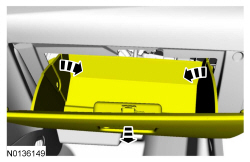
- Detach the glove compartment damper and lower the glove compartment.
- Remove the cabin air filter access door.
- Remove the cabin air filter.
- To install, reverse the removal procedure.
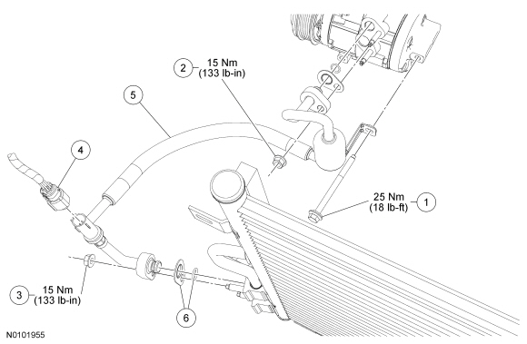
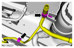
Compressor to Condenser Discharge Line - 2.0L GTDI
Removal and Installation
- With the vehicle in NEUTRAL, position it on a hoist. For additional information, refer to Section 100-02.
- Recover the refrigerant. For additional information, refer to Section 412-00.
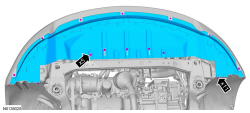
- Release the 4 underbody shield retainers and remove the underbody shield (if equipped).
- Remove the lower radiator splash shield.

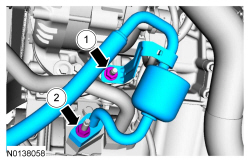
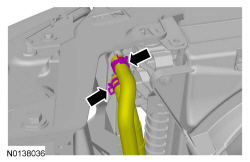
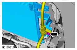
- Disconnect the A/C pressure transducer electrical connector, remove the
condenser inlet fitting nut and disconnect the fitting.
- To install, tighten to 15 Nm (133 lb-in).
- Remove the compressor-to-condenser discharge line.
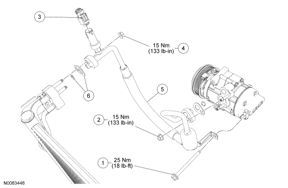
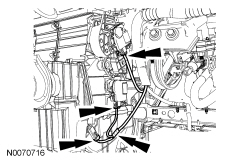
- Remove the rear A/C compressor bolt.
- To install, tighten to 25 Nm (18 lb-ft).
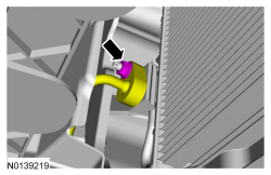
- Remove the A/C compressor discharge fitting nut and disconnect the
fitting.
- To install, tighten to 15 Nm (133 lb-in).
- Remove the rear A/C compressor bolt.
- To install, reverse the removal procedure.
- Install new gasket seals and O-ring seals.
- Add the correct amount of clean PAG oil to the refrigerant system. For additional information, refer to Section 412-00.
- Evacuate, leak test and charge the refrigerant system. For additional information, refer to Section 412-00.
Compressor to Condenser Discharge Line - 3.5L Ti-VCT
Material
Removal and Installation
- Recover the refrigerant. For additional information, refer to Section 412-01.
- Remove the rear A/C compressor bolt.
- To install, tighten to 25 Nm (18 lb-ft).
- Remove the A/C compressor discharge fitting nut and disconnect the
fitting.
- Discard the O-ring seal and gasket seal.
- To install, tighten to 15 Nm (133 lb-in).
- Disconnect the A/C pressure transducer electrical connector.
- Remove the condenser inlet fitting nut and disconnect the fitting.
- Discard the O-ring seal and gasket seal.
- To install, tighten to 15 Nm (133 lb-in).
- Remove the compressor-to-condenser discharge line.
- To install, reverse the removal procedure.
- Install new gasket seals and O-ring seals.
- Add the correct amount of clean PAG oil. For additional information, refer to the Refrigerant Oil Adding procedure in Section 412-00.
- Evacuate, leak test and charge the refrigerant system. For additional information, refer to Section 412-00.
Compressor to Condenser Discharge Line - 3.5L GTDI
Material
Removal and Installation
- With the vehicle in NEUTRAL, position it on a hoist. For additional information, refer to Section 100-02.
- Recover the refrigerant. For additional information, refer to Section 412-00.
- Release the 4 underbody shield retainers and remove the underbody shield (if equipped).

- Remove the lower radiator splash shield.

- Remove the rear A/C compressor bolt.
- To install, tighten to 25 Nm (18 lb-ft).
- Remove the A/C compressor discharge fitting nut and disconnect the
fitting.
- To install, tighten to 15 Nm (133 lb-in).
- Remove the condenser inlet fitting nut and disconnect the fitting.
- To install, tighten to 15 Nm (133 lb-in).
- Disconnect the A/C pressure transducer electrical connector.
- Remove the compressor-to-condenser discharge line.
- To install, reverse the removal procedure.
- Install new gasket seals and O-ring seals.
- Add the correct amount of clean PAG oil to the refrigerant system. For additional information, refer to the Refrigerant Oil Adding procedure in Section 412-00.
- Evacuate, leak test and charge the refrigerant system. For additional information, refer to Section 412-00.
Condenser Core - 3.5L Ti-VCT
Material
Removal and Installation
- With the vehicle in NEUTRAL position it on a hoist. For additional information, refer to Section 100-02.
- Recover the refrigerant. For additional information, refer to Section 412-00.
- Remove the radiator. For additional information, refer to Section 303-03.
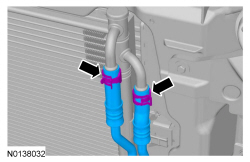
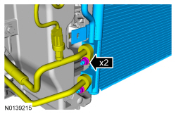
- Release the 2 transmission cooler line clamps and disconnect the lines from the condenser core.
- Remove the condenser inlet fitting nut and disconnect the fitting.
- Discard the O-ring seals and gasket seals.
- To install, tighten to 15 Nm (133 lb-in).
- Remove the condenser outlet fitting nut and disconnect the fitting,
remove the condenser core.
- Discard the O-ring seals and gasket seals.
- To install, tighten to 15 Nm (133 lb-in).
- To install, reverse the removal procedure.
- Install new gasket seals and O-ring seals.
- Add the correct amount of clean PAG oil to the refrigerant system. For additional information, refer to the Refrigerant Oil Adding procedure in Section 412-00.
- Evacuate, leak test and charge the refrigerant system. For additional information, refer to Section 412-00.
- Fill the transmission fluid to the correct level. For additional information, refer to Section 307-01A.
Condenser Core - 2.0L GTDI
Material
Removal and Installation
- With the vehicle in NEUTRAL position it on a hoist. For additional information, refer to Section 100-02.
- Recover the refrigerant. For additional information, refer to Section 412-00.
- Remove the grille shutter assembly. For additional information, refer to Section 501-02.
- Release the 2 transmission cooler line clamps and disconnect the lines from the condenser core.
- To install, tighten to 6Nm (53 lb-in).
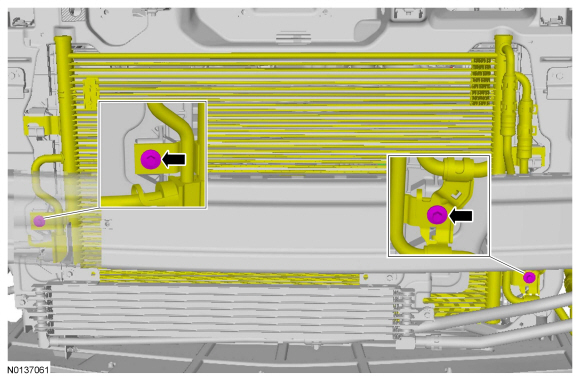
- Remove the 2 condenser fitting nuts and disconnect the fitting, and
remove the condenser core.
- Discard the O-ring seals and gasket seals.
- To install, tighten to 15 Nm (133 lb-in).
- To install, reverse the removal procedure.
- Install new gasket seals and O-ring seals.
- Add the correct amount of clean PAG oil to the refrigerant system. For additional information, refer to the Refrigerant Oil Adding procedure in Section 412-00.
- Evacuate, leak test and charge the refrigerant system. For additional information, refer to Section 412-00.
- Fill the transmission fluid to the correct level. For additional information, refer to Section 307-01A.
Condenser Core - 3.5L GTDI
Removal and Installation
- With the vehicle in NEUTRAL position it on a hoist. For additional information, refer to Section 100-02.
- Recover the refrigerant. For additional information, refer to Section 412-00.
- Remove the front bumper cover.. For additional information, refer to Section 501-19.
- Release the 2 transmission cooler line clamps and disconnect the lines from the condenser core.

- To install, tighten to 6 Nm (53 lb-in).

- Remove the 2 condenser fitting nuts and disconnect the fitting, and
remove the condenser core.
- Discard the O-ring seals and gasket seals.
- To install, tighten to 15 Nm (133 lb-in).

- To install, reverse the removal procedure.
- Install new gasket seals and O-ring seals.
- Add the correct amount of clean PAG oil to the refrigerant system. For additional information, refer to the Refrigerant Oil Adding procedure in Section 412-00.
- Evacuate, leak test and charge the refrigerant system. For additional information, refer to Section 412-00.
- Fill the transmission fluid to the correct level. For additional information, refer to Section 307-01A.
Evaporator Core
Removal and Installation
NOTE: The evaporator core is available only as part of the evaporator core housing assembly.
- Remove the heater core and evaporator core housing. For additional information, refer to Heater Core And Evaporator Core Housing in this section.
- Transfer the components from the old housing to the new housing as needed.
- Install the heater core and evaporator core housing. For additional information, refer to Heater Core And Evaporator Core Housing in this section.
Heater Core
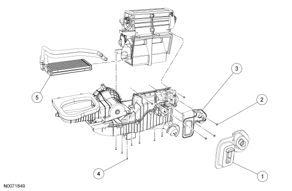
Removal and Installation
NOTE: If a heater core leak is suspected, the heater core must be pressure leak tested before it is removed from the vehicle. For additional information, refer to Section 412-00.
- Remove the heater core and evaporator core housing. For additional information, refer to Heater Core And Evaporator Core Housing in this section.
- Remove the dash panel seal.
- Remove the 3 heater core tube support bracket screws and heater core tube support bracket.
- Remove the 10 plenum chamber screws and separate the heater core and evaporator housing.
- Remove the heater core and seal assembly.
- To install, reverse the removal procedure.
Heater Core And Evaporator Core Housing
Material
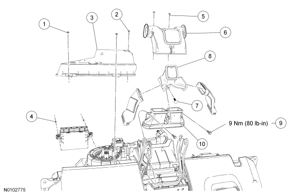
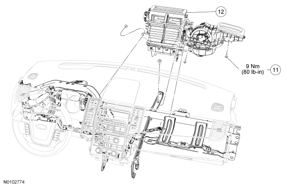
Removal and Installation
- Remove the instrument panel. For additional information, refer to Section 501-12.
- Remove the 3 RH lower instrument panel insulator screws and position the insulator aside.
- Remove the 2 Remote Function Actuator (RFA) module nuts and position the module aside (if equipped).
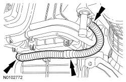
- Detach and position the in-vehicle temperature sensor aspirator hose aside.
- Remove the 2 floor duct screws and the floor duct.
- Detach the console duct Y-adapter pin-type retainer and remove the Y-adapter.
- Remove the 2 floor duct adapter bolts and detach the floor duct adapter
from the heater core and evaporator core housing.
- To install, tighten to 9 Nm (80 lb-in).
- Disconnect the 3 electrical connectors and detach the wire harness pin-type retainer.
- Detach the 4 wire harness pin-type retainers and disconnect the electrical connector.
- Disconnect the 3 electrical connectors, detach the wire harness pin-type retainer and detach the instrument panel harness from the heater core and evaporator core housing,
- Remove the 4 heater core and evaporator core housing bolts.
- To install, tighten to 9 Nm (80 lb-in).
- Remove the heater core and evaporator core housing.
- To install, reverse the removal procedure.
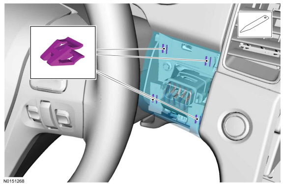
Heating Ventilation Air Conditioning (HVAC) Module
Removal and Installation
- Remove the Audio Front Control Module (ACM). Refer to the appropriate section in Group 415 for the procedure.
- Remove the HVAC module retainer, and position aside.
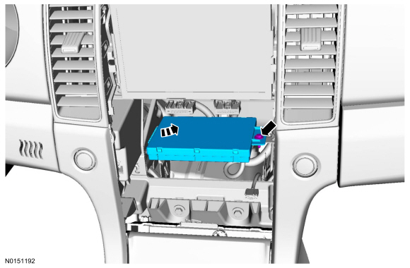
- Disconnect the 3 HVAC module electrical connectors and remove the HVAC module.
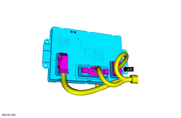
- To install, reverse the removal procedure.
In-Vehicle Temperature and Humidity Sensor
NOTE: Taurus and Police Interceptor vehicles with floor console shown; Police Interceptor vehicles without floor console, the in-vehicle temperature and humidity sensor is located behind the lower center instrument panel finish panel.
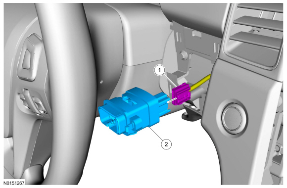
Removal and Installation
Taurus and Police Interceptor vehicles with floor console
- Remove the in-vehicle temperature and humidity sensor cover.
Police Interceptor vehicles without floor console
- Remove the lower center instrument panel finish panel.
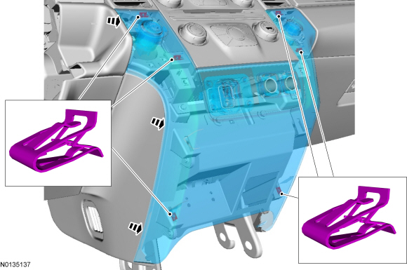
All vehicles
- NOTE: Taurus and Police Interceptor vehicles with floor console
shown, Police Interceptor vehicles without floor console similar.
Disconnect the electrical connector, remove the in-vehicle temperature and humidity sensor.
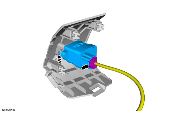
- To install, reverse the removal procedure.
Mode Door Actuator - Air Inlet Door
Removal and Installation
- Detach the glove compartment damper and lower the glove compartment.

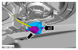
- Disconnect the air inlet door actuator electrical connector, remove the 2 retainers and the air inlet door actuator.
- To install, reverse the removal procedure.
Mode Door Actuator - Defrost/Panel/Floor Door
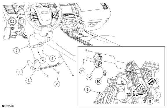
Removal and Installation
- Remove the Instrument Panel Cluster (IPC). For additional information, refer to Section 413-01.
- Remove the 4 knee bolster bolts and the knee bolster.
- Remove the 2 lower steering column shroud screws and the lower steering column shroud.
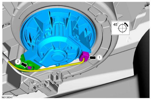
- NOTICE: Do not press the brake pedal when removing or
installing the speed control deactivator switch, as the switch will be
damaged.
Remove the speed control deactivator switch.
- Rotate the speed control deactivator switch counterclockwise 45 degrees and remove the deactivator switch.
- Detach the 3 wire harness-to-brake pedal bracket pin-type retainers from the top of the brake pedal bracket.
- Disconnect the defrost/panel/floor mode door actuator electrical connector.
- NOTE: The upper rear defrost/panel/floor mode door actuator screw
can be accessed through the Instrument Panel Cluster (IPC) opening using a
swivel-type socket and extension.
Remove the 3 defrost/panel/floor mode door actuator screws.
- Remove the defrost/panel/floor mode door actuator.
- To install, reverse the removal procedure.
- NOTE: The purpose of the module actuator position calibration is
to allow the HVAC module to reinitialize and calibrate the actuator stop
points. To carry out calibration, carry out the following steps.
Remove Smart Junction Box (SJB) fuse 15 for at least one minute.
- NOTE: When the ignition switch is switched to the ON position,
the HVAC module will initialize and calibrate the actuators. Calibration of
the actuators will take approximately 30 seconds.
Reinstall SJB fuse 15. Turn the ignition switch to the ON position and wait 30 seconds before verifying correct mode door operation.
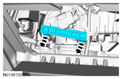
Receiver Drier
Material
Removal and Installation
NOTICE: Care must be taken to minimize exposure of the inside of the receiver/drier to outside air. If multiple Air Conditioning (A/C) system components are being removed and installed, the receiver/drier should be installed last. The receiver/drier shipping caps should not be removed until the fittings are ready to be connected. Evacuation of the A/C system must be started as soon as the receiver/drier is installed. Excessive exposure of the inside of the receiver/drier to outside air will result in moisture contamination of the receiver/drier desiccant.
NOTE: Installation of a new receiver/drier is not required when repairing the A/C system, except when there is physical evidence of contamination from a failed A/C compressor or damage to the receiver/drier. Damage to the receiver/drier includes leaks in the receiver/drier, physical damage to the receiver/drier shell or desiccant, or moisture contamination. Moisture contamination results only from a complete loss of refrigerant and equalization of the refrigerant system pressure with atmospheric pressure for a period longer than one hour. If even a slight amount of positive refrigerant pressure is present in the system before repairs are carried out, the receiver/drier should not be replaced.
- With the vehicle in NEUTRAL, position it on a hoist. For additional information, refer to Section 100-02.
- Recover the refrigerant. For additional information, refer to Section 412-00.
- Release the 4 underbody shield retainers and remove the underbody shield (if equipped).

- Remove the lower radiator splash shield.

- Remove the condenser outlet fitting nut and disconnect the fitting.
- Discard the O-ring seal and gasket seal.
- To install, tighten to 15 Nm (133 lb-in).
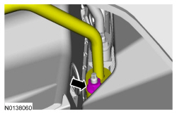
- Detach the receiver/drier outlet line clip, and remove the
receiver/drier outlet fitting nut and disconnect the fitting.
- Discard the O-ring seal and gasket seal.
- To install, tighten to 15 Nm (133 lb-in).

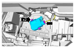
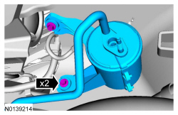
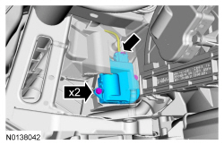
- Remove the bolts and position the degas bottle aside
- To install, tighten to 9 Nm (80 lb-in).
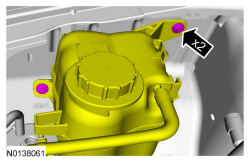
- Remove the 2 receiver/dryer bolts and remove the receiver/dryer.
- To install, tighten to 9 Nm (80 lb-in).
- To install, reverse the removal procedure.
- Install new gasket seals and O-ring seals.
- Add the correct amount of clean PAG oil to the refrigerant system. For additional information, refer to the Refrigerant Oil Adding procedure in Section 412-00.
- Evacuate, leak test and charge the refrigerant system. For additional information, refer to Section 412-00.
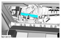
Receiver Drier Cartridge
Material
Removal
NOTE: Installation of a new receiver/drier desiccant bag is not required when repairing the A/C system, except when there is physical evidence of contamination from a failed A/C compressor or damage to the receiver/drier desiccant bag. Damage to the receiver/drier desiccant bag includes physical damage to the receiver/drier desiccant bag or moisture contamination. Moisture contamination results only from a complete loss of refrigerant and equalization of the refrigerant system pressure with atmospheric pressure for a period longer than one hour. If even a slight amount of positive refrigerant pressure is present in the system before repairs are carried out, the receiver/drier desiccant bag should not be replaced.
- With the vehicle in NEUTRAL, position it on a hoist. For additional information, refer to Section 100-02.
- Recover the refrigerant. For additional information, refer to Section 412-00.
- Release the 4 underbody shield retainers and remove the underbody shield (if equipped).

- Remove the lower radiator splash shield.

- Visually inspect the access hole. If the inner bolster flash covers any portion of the receiver drier plug and/or is not aligned with the 40 mm (1.574 in) access hole proceed to step 6. If there are no clearance issues proceed to step 7.
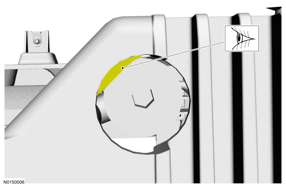
- Remove 3.0 mm (0.118 in) of material from the inner bolster flash.
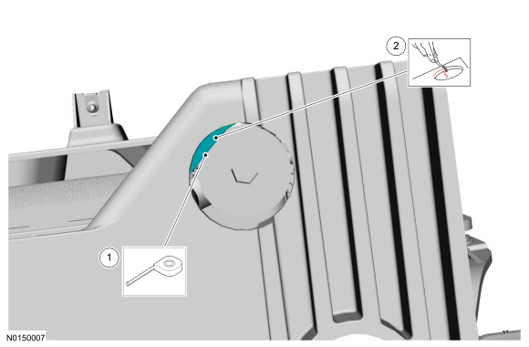
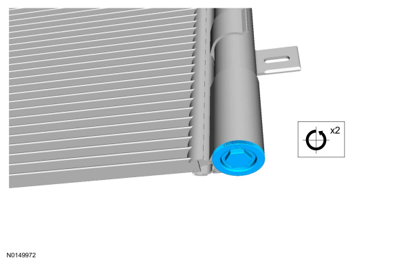
- Unscrew and remove the plastic receiver/drier cap.
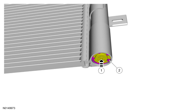
- Remove the receiver/drier plug snap ring.
- Push the receiver/drier plug upwards.
- Remove the receiver/drier plug snap ring.
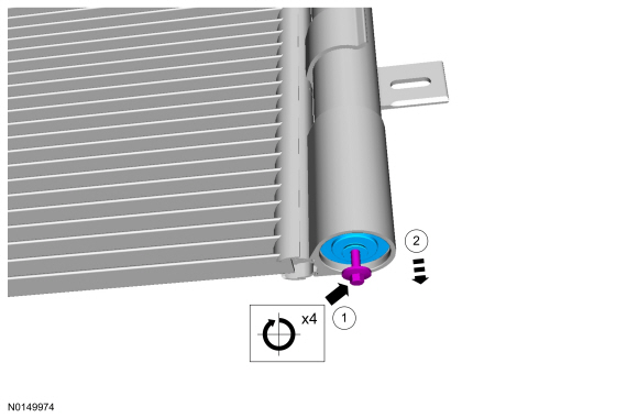
- Remove the receiver/drier plug.
- Install an M5 bolt in the center of the receiver drier plug.
- Remove the receiver/drier plug.
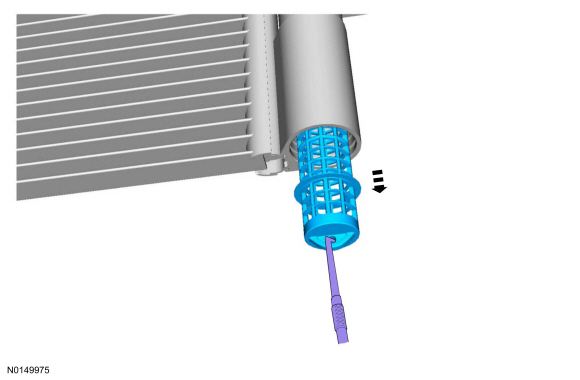
- Grasp the receiver/drier cartridge grab handle and remove the receiver/drier cartridge.
Installation
- To install, reverse the removal procedure.
- Install new gasket seals and O-ring seals.
- Add the correct amount of clean PAG oil to the refrigerant system. For additional information, refer to the Refrigerant Oil Adding procedure in Section 412-00.
- Evacuate, leak test and charge the refrigerant system. For additional information, refer to Section 412-00.
Register - Center
Removal and Installation
- Remove the center instrument panel finish panel. For additional information, refer to Section 501-12.
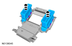
- Release the clips and remove the center registers.
- To install, reverse the removal procedure.
Register - Driver Side
Removal and Installation
- Remove the instrument cluster finish panel. For additional information, refer to Section 501-12.
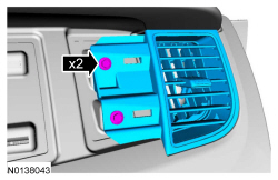
- Remove the 2 LH register screws, and remove the LH register.
- To install, reverse the removal procedure.
Register - Passenger Side
Removal and Installation
- Remove the instrument panel finish panel. For additional information, refer to Section 501-12.
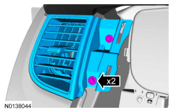
- Remove the 2 RH register screws and remove the RH register.
- To install, reverse the removal procedure.
Temperature Blend Door Actuator - LH
Removal and Installation
NOTE: The LH temperature blend door actuator can be accessed from below the LH side of the instrument panel.
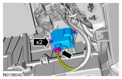
- Disconnect the LH temperature blend door actuator electrical connector, remove the 2 retainers and the LH temperature blend door actuator.
- To install, reverse the removal procedure.
- NOTE: The purpose of the module actuator position calibration is
to allow the HVAC module to reinitialize and calibrate the actuator stop
points. To carry out calibration, carry out the following steps.
Remove Smart Junction Box (SJB) fuse 15 for at least one minute.
- NOTE: When the ignition switch is switched to the ON position,
the HVAC module will initialize and calibrate the actuators. Calibration of
the actuators will take approximately 30 seconds.
Reinstall SJB fuse 15. Turn the ignition switch to the ON position and wait 30 seconds before verifying correct LH temperature blend door operation.
Temperature Blend Door Actuator - RH
Removal and Installation
- Detach the glove compartment damper and lower the glove compartment.

- Working through the glove compartment opening, detach the instrument panel wire harness pin-type retainer from the heater core and evaporator core housing support.
- Remove the 2 RH temperature blend door actuator screws. Reposition the RH temperature blend door actuator to allow access to the electrical connector and disconnect the RH temperature blend door actuator electrical connector. Remove the RH temperature blend door actuator.
- To install, reverse the removal procedure.
- NOTE: The purpose of the module actuator position calibration is
to allow the HVAC module to reinitialize and calibrate the actuator stop
points. To carry out calibration, carry out the following steps.
Remove Smart Junction Box (SJB) fuse 15 for at least one minute.
- NOTE: When the ignition switch is switched to the ON position,
the HVAC module will initialize and calibrate the actuators. Calibration of
the actuators will take approximately 30 seconds.
Reinstall SJB fuse 15. Turn the ignition switch to the ON position and wait 30 seconds before verifying correct RH temperature blend door operation.
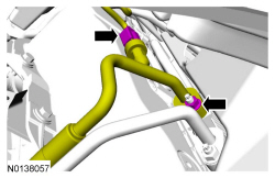
Thermostatic Expansion Valve
Material
Removal and Installation
- Recover the refrigerant. For additional information, refer to Section 412-00.
- Detach the brake booster vacuum hose retainer from the strut tower brace.

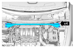
- NOTE: RH side of strut tower brace shown, LH similar.
Remove the 4 nuts and the strut tower brace.
- To install, tighten to 30 Nm (22 lb-ft).
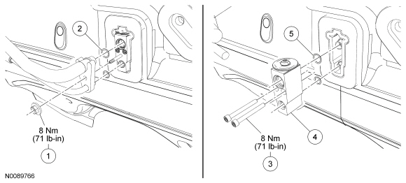
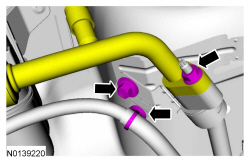
- Remove the Thermostatic Expansion Valve (TXV) fitting nut.
- Discard the O-ring seals.
- To install, tighten to 8 Nm (71 lb-in).
- Remove the 2 TXV bolts.
- To install, tighten to 8 Nm (71 lb-in).
- Remove the TXV.
- Discard the O-ring seals.
- To install, reverse the removal procedure.
- Install new O-ring seals and gasket seals.
- Add the correct amount of clean PAG oil. For additional information, refer to the Refrigerant Oil Adding procedure in Section 412-00
- Evacuate, leak test and charge the refrigerant system. For additional information, refer to Section 412-00.
Thermostatic Expansion Valve Manifold and Tube Assembly - 2.0L GTDI, 3.5L GTDI
Material
Removal and Installation
- With the vehicle in NEUTRAL, position it on a hoist. For additional information, refer to Section 100-02.
- Recover the refrigerant. For additional information, refer to Section 412-00.
- Detach the brake booster vacuum hose retainer from the strut tower brace.

- Remove the 4 nuts and the strut tower brace.
- To install, tighten to 30 Nm (22 lb-ft).
- Remove the cowl panel grille. For additional information, refer to Section 501-02.
- Disconnect the 2 PCM electrical connectors.
- Detach the wiring harness retainer and disconnect the electrical connector.
- Remove the engine wiring harness retainer from the bulkhead.
- Push the wiring harness retainer tab in.
- Slide the wiring harness up and out of the bulkhead.
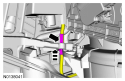
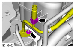
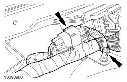
- Detach the routing clip pin-type retainer from the Thermostatic
Expansion Valve (TXV) manifold and tube bracket. Remove the TXV manifold and
tube bracket bolt, evaporator outlet line fitting nut and disconnect the
fitting.
- Discard the O-ring seal and gasket seal.
- To install, tighten to 15 Nm (133 lb-in).
- Detach the receiver/drier outlet line clip, and remove the
receiver/drier outlet fitting nut and disconnect the fitting.
- Discard the O-ring seal and gasket seal.
- To install, tighten to 15 Nm (133 lb-in).
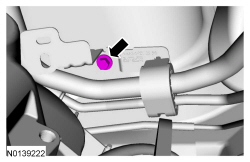
- Remove the bolt and ground wire from the RH shock tower.
- To install, tighten to 10 Nm (89 lb-in).
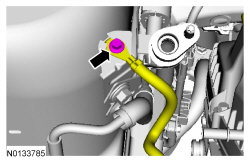
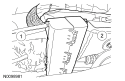
- Remove the TXV manifold and tube clamp bracket bolt.
- To install, tighten to 9 Nm (80 lb-in).
- Remove the TXV fitting nut and disconnect the fitting, and remove
the TXV manifold and tube assembly.
- Discard the O-ring seals.
- To install, tighten to 15 Nm (133 lb-in).
- To install, reverse the removal procedure.
- Install new gasket seals and O-ring seals.
- Add the correct amount of clean PAG oil to the refrigerant system. For additional information, refer to the Refrigerant Oil Adding procedure in Section 412-00.
- Evacuate, leak test and charge the refrigerant system. For additional information, refer to Section 412-00.
Thermostatic Expansion Valve Manifold and Tube Assembly - 3.5L Ti-VCT
Removal and Installation
- With the vehicle in NEUTRAL, position it on a hoist. For additional information, refer to Section 100-02.
- Recover the refrigerant. For additional information, refer to Section 412-00.
- Detach the brake booster vacuum hose retainer from the strut tower brace.
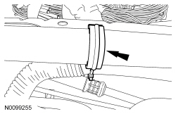
- NOTE: RH side of strut tower brace shown, LH similar.
Remove the 4 nuts and the strut tower brace.
- To install, tighten to 30 Nm (22 lb-ft).

- Remove the cowl panel grille. For additional information, refer to Section 501-02.
- Disconnect the 2 PCM electrical connectors.
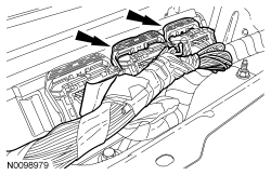
- Detach the wiring harness retainer and disconnect the electrical connector.
- Remove the engine wiring harness retainer from the bulkhead.
- Push the wiring harness retainer tab in.
- Slide the wiring harness up and out of the bulkhead.
- Detach the routing clip pin-type retainer from the Thermostatic
Expansion Valve (TXV) manifold and tube bracket. Remove the TXV manifold and
tube bracket bolt, evaporator outlet line fitting nut and disconnect the
fitting.
- Discard the O-ring seal and gasket seal.
- To install, tighten to 15 Nm (133 lb-in).

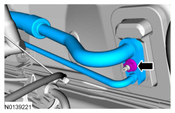
- Detach the evaporator inlet line clips.
- Release the 4 underbody shield retainers and remove the underbody shield (if equipped).

- Remove the lower radiator splash shield.
- Remove the condenser outlet fitting nut and disconnect the fitting.
- Discard the O-ring seal and gasket seal.
- To install, tighten to 15 Nm (133 lb-in).

- Remove the TXV manifold and tube clamp bracket bolt.
- To install, tighten to 9 Nm (80 lb-in).

- Remove the TXV fitting nut and disconnect the fitting, and remove
the TXV manifold and tube assembly.
- Discard the O-ring seals.
- To install, tighten to 15 Nm (133 lb-in).

- To install, reverse the removal procedure.
- Install new gasket seals and O-ring seals.
- Add the correct amount of clean PAG oil to the refrigerant system. For additional information, refer to the Refrigerant Oil Adding procedure in Section 412-00.
- Evacuate, leak test and charge the refrigerant system. For additional information, refer to Section 412-00.
 Specifications, Description and Operation
SPECIFICATIONS
Material
Torque Specifications
DESCRIPTION AND OPERATION
Air Conditioning
The A/C system components include the following:
A/C compressor and clutch assembly
A/C condenser core
A/ ...

Other materials:
Body Closures
SPECIFICATIONS
Torque Specifications
GENERAL PROCEDURES
Door Adjustment - Front
Loosen the front door hinge-to-front door bolts until the front door is
able to move slightly.
Align the front door.
Align the front door body angles to the rear door.
Be sure that the front door is flush ...
Diagnosis and Testing
Safety Belt System
Principles of Operation
WARNING: All
safety belt components must be inspected and corrected as part of any collision
repair. Inspect all safety belt components as prescribed by Safety Belt
Inspection and Repair After a Collision found in Section 501-20A General
Procedure ...
Starting System
SPECIFICATIONS
General Specifications
Torque Specifications
DESCRIPTION AND OPERATION
Starting System
Starting System - without Push Button Start
Overview
The starter system controls the cranking of the engine. The starter motor is
enabled by the starter relay when the relay is activated by the& ...
