SPECIFICATIONS
Material
Torque Specifications
DESCRIPTION AND OPERATION
Air Conditioning
The A/C system components include the following:
- A/C compressor and clutch assembly
- A/C condenser core
- A/C evaporator core
- Receiver/drier cartridge (3.5L Ti-VCT engine)
- Receiver/drier (2.0L/3.5L GTDI engine)
- Connecting refrigerant lines
- TXV
An A/C pressure relief valve is installed in the A/C compressor to protect the refrigerant system against excessively high refrigerant pressures.
Refrigerant flow into the evaporator core is metered by a TXV.
A/C Compressor and Clutch Assembly
NOTE: The A/C compressor components are not serviced separately. The A/C compressor and clutch is serviced only as an assembly.
The A/C compressor has the following characteristics:
- A non-serviceable shaft seal.
- A non-serviceable pressure relief valve is installed in the rear of the compressor to protect the refrigerant system against excessively high refrigerant pressures.
- Uses PAG oil or equivalent. This oil contains special additives required for the A/C compressor.
- The oil may have some slightly dark-colored streaks while maintaining normal oil lubricant properties. This is normal for this A/C compressor because of break-in wear that can discolor the oil.
- Use the refrigerant oil adding procedure specified for this vehicle when installing a new A/C compressor. Refer to Section 412-00.
When battery voltage is applied to the A/C compressor clutch field coil, the clutch disc and hub assembly is drawn toward the A/C clutch pulley. The magnetic force locks the clutch disc and hub assembly and the A/C clutch pulley together as one unit, causing the compressor shaft to rotate. When battery voltage is removed from the A/C compressor clutch field coil, springs in the clutch disc and hub assembly move the clutch disc away from the A/C clutch pulley.
Externally Controlled Variable Displacement Air Conditioning (A/C) Compressor
The externally controlled variable displacement A/C compressor has the following characteristics:
- a non-servicable shaft seal
- a non-servicable pressure relief valve installed in the rear of the compressor to protect the refrigerant system against excessively high refrigerant pressures
- uses PAG oil or equivalent. This oil contains special additives required for the A/C compressor. The oil may have some slightly dark-colored streaks while maintaining normal viscosity. This is normal for the A/C compressor because of break-in wear that can discolor the oil.
The externally controlled variable displacement A/C compressor is electronically controlled by the PCM. The PCM pulse width modulates the ground to the externally controlled variable displacement A/C compressor solenoid to change the displacement of the A/C compressor by changing the swash plate angle based upon the:
- evaporator temperature
- ambient air temperature
- engine revolutions per minute
- vehicle speed
- A/C hide side pressure
- intake air temperature
A/C Condenser/Transmission Oil Combo Cooler
NOTE: The A/C condenser/transmission oil combo cooler for the 3.5L Ti-VCT engine equipped vehicles is produced from the factory with a receiver/drier desiccant bag installed in the integrated receiver/drier. This receiver/drier desiccant bag may become contaminated with moisture if the A/C condenser is not installed for an extended period of time. Since it cannot be determined how much time has elapsed between production and installation of the unit as a service part, remove and replace the receiver/drier desiccant bag with the separate receiver/drier desiccant bag supplied with the A/C condenser service part kit.
The A/C condenser/transmission oil combo cooler is an aluminum fin-and-tube design heat exchanger located in front of the vehicle radiator. It cools compressed refrigerant gas by allowing air to pass over fins and tubes to extract heat and by condensing gas to liquid refrigerant as it is cooled.
The top portion of the A/C condenser/transmission oil combo cooler is partitioned from the refrigerant system and is used for transmission oil cooling.
Receiver/Drier
NOTE: It is not necessary to install a new receiver/drier when repairing the A/C system, except when there is physical evidence of contamination from a failed A/C compressor or damage to the receiver/drier. Damage to the receiver/drier includes leaks in the receiver/drier, physical damage to the receiver/drier shell or desiccant, or moisture contamination. Moisture contamination results only from a complete loss of refrigerant and equalization of the refrigerant system pressure with atmospheric pressure for a period longer than one hour. If even a slight amount of positive refrigerant pressure is present in the system before repairs are carried out, the receiver/drier should not be replaced.
The receiver/drier stores high-pressure liquid and the desiccant bag mounted inside the receiver/drier removes any retained moisture from the refrigerant.
For 3.5L Ti-VCT engine equipped vehicles, the receiver/drier is integral to the A/C condenser. The receiver/drier cartridge is a separate component and can be removed and installed with the A/C condenser in the vehicle.
For 2.0L/3.5L GTDI engine equipped vehicles, the receiver/drier is mounted between the condenser outlet and the TXV manifold and tube assembly.
Evaporator Core
NOTE: The evaporator core is available only as part of the heater core and evaporator core housing.
The evaporator core is an aluminum plate/fin type and is located in the heater core and evaporator core housing. A mixture of liquid refrigerant and oil enters the bottom of the evaporator core through the evaporator core inlet tube and continues out of the evaporator core through the evaporator core outlet tube as a vapor. During A/C compressor operation, airflow from the blower motor is cooled and dehumidified as it flows through the evaporator core fins.
TXV
The TXV provides a restriction to the flow of refrigerant from the high-pressure side of the refrigerant system and separates the low-pressure and high-pressure sides of the refrigerant system. Refrigerant entering and exiting the evaporator core passes through the TXV through 2 separate flow paths. An internal temperature sensing bulb senses the temperature of the refrigerant flowing out of the evaporator core and adjusts an internal pin-type valve to meter the refrigerant flow into the evaporator core. The internal pin-type valve decreases the amount of refrigerant entering the evaporator core at lower temperatures and increases the amount of refrigerant entering the evaporator core at higher temperatures.
Evaporator Temperature Sensor
NOTE: The evaporator temperature sensor is not available as a separate component. To install a new evaporator temperature sensor, a new heater core and evaporator core housing must be installed.
The evaporator temperature sensor contains a thermistor which receives a reference voltage from the HVAC module. The thermistor then varies the resistance to the reference voltage based on the evaporator fin temperature. The resulting voltage is interpreted as an evaporator fin temperature reading.
The HVAC module maintains evaporator core temperature and prevents the evaporator core from icing. This is accomplished by switching the A/C request signal off when the evaporator temperature sensor reading falls below acceptable levels, and by switching the A/C request signal on when the evaporator temperature rises above acceptable levels.
The evaporator temperature sensor electrical connector is located outside of the heater core and evaporator core housing near the accelerator pedal, with the sensor pigtail leading into the housing to the sensor probe inserted between the evaporator core fins.
A/C Pressure Transducer
The A/C pressure transducer monitors the compressor discharge pressure and sends a variable voltage signal representing the pressure to the PCM. The PCM interrupts A/C compressor operation in the event the A/C pressure transducer indicates high system discharge pressures. It is also used to sense low charge conditions. The PCM prevents the A/C clutch from engaging if the pressure is below a predetermined value for a given ambient temperature. It is not necessary to recover the refrigerant before removing the A/C pressure transducer.
Service Gauge Port Valves
The high-pressure service gauge port valve is located on the compressor-to-condenser discharge line.
The low-pressure service gauge port valve is located on the compressor suction line.
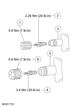
The fitting is an integral part of the refrigerant line or component.
- Special couplings are required for both the high-side and low-side service gauge ports.
- A very small amount of leakage around the Schrader-type valve with the service gauge port valve cap removed is considered normal. Install a new Schrader-type valve core if the seal leaks excessively.
- The A/C service gauge port valve caps are used as primary seals in the refrigerant system to prevent leakage through the Schrader-type valves from reaching the atmosphere. Always install and tighten the A/C service gauge port valve caps to the correct torque after they are removed.
Refrigerant System Dye
A fluorescent refrigerant system dye wafer is added to the receiver/drier desiccant bag to assist in refrigerant system leak diagnosis using a Rotunda-approved UV blacklight. This fluorescent dye wafer dissolves after about 30 minutes of continued A/C operation. It is not necessary to add additional dye to the refrigerant system before diagnosing leaks, even if a significant amount of refrigerant has been removed from the system.
Air Distribution and Filtering
Air Distribution
NOTE: This vehicle is factory equipped with a cabin air filter.
There are 2 sources of air available to the air distribution system:
- Outside air
- Recirculated air
Recirculated air is always used when the HVAC module is set to the MAX A/C mode on vehicles equipped with Electronic Manual Temperature Control (EMTC). Vehicles equipped with dual-zone Electronic Automatic Temperature Control (EATC) use recirculated air only when the RECIRC function is selected in any mode other than DEFROST, or when required by the HVAC module in the AUTOMATIC mode.
Air distribution within the vehicle is determined by the function selected ( EMTC ), or the dual-zone EATC system in the AUTOMATIC mode. The air distribution mode on vehicles equipped with dual-zone EATC can be overridden by the driver if desired. Airflow mode control doors are used to direct airflow within the heater core and evaporator core housing. Electric mode door actuators are used to position these airflow mode doors.
Vehicles equipped with dual-zone EATC use 2 separate temperature blend doors. This allows individual temperature settings to be selected for the RH and LH air outlets. The airflow mode doors are not partitioned for separate RH and LH airflow positions. Therefore, the airflow mode will always remain similar for the RH and LH sides of the vehicle regardless of the temperatures selected.
Air enters the passenger compartment from the:
- instrument panel registers.
- floor duct.
- windshield defroster.
- side window demisters.
- rear footwell duct (if equipped).
Passenger compartment air is exhausted from the vehicle through open windows or body air vents located near the rear lamp assemblies.
Cabin Air Filter
NOTE: A cabin air filter must be installed for correct climate control system NVH performance.
The vehicle is factory equipped with a cabin air filter. The cabin air filter is positioned at the blower motor inlet and filters both fresh and recirculated air. The cabin air filter can be accessed though the glove compartment.
For cabin air filter maintenance intervals, refer to Section 100-03.
Control Components
EMTC
The EMTC components are used to select:
- air inlet source (outside or recirculated).
- blower motor speed.
- discharge air temperature (temperature blend).
- discharge air location (defrost, panel, floor).
- A/C compressor operation.
Control System Inputs
HVAC Module
The EMTC system uses a remote HVAC module that is separate from the control interface. The FCIM provides the interface for the vehicle occupants to control the climate control system. When selections are made, the FCIM communicates the selections to the HVAC module through the vehicle module communication network. The remote HVAC module controls the climate control system based on the FCIM selections.
In-Vehicle Temperature/Humidity Sensor
The in-vehicle temperature/humidity sensor contains 2 thermistors which separately measure the in-vehicle air temperature and humidity and send those readings to the HVAC module. The in-vehicle temperature/humidity sensor has an electric fan within the sensor that draws in-vehicle air across the thermistors.
Control System Outputs
The EMTC system has 4 system outputs.
Blower Motor Speed
The blower motor speed control controls the blower motor speed by converting low power signals from the HVAC module to a high-current, variable ground feed for the blower motor. A delay function provides a gradual increase or decrease in blower motor speed under all conditions.
Temperature Blend Door Position
The temperature blend door actuator moves the temperature blend door on command from the HVAC module.
The temperature blend door actuator contains a reversible electric motor and a potentiometer. The potentiometer circuit consists of a 5-volt reference signal connected to one end of a variable resistor, and a signal ground connected to the other. A signal circuit is connected to a contact wiper, which is driven along the variable resistor by the actuator shaft. The signal to the HVAC module from the contact wiper indicates the position of the temperature blend door. The HVAC module powers the actuator motor to move the temperature blend door to the desired position selected by the vehicle's occupants.
Defrost/Panel/Floor Mode Door Position
Airflow through the HVAC plenum is controlled by the defrost/panel/floor mode door actuator. The defrost/panel/floor mode door actuator contains a reversible electric motor and potentiometer. The potentiometer allows the HVAC module to monitor the position of the defrost/panel/floor mode door. The potentiometer circuit consists of a 5-volt reference signal connected to one end of a variable resistor, and a signal ground connected to the other. A signal circuit is connected to a contact wiper, which is driven along the variable resistor by the actuator shaft. The signal to the HVAC module from the contact wiper indicates the position of the defrost/panel/floor mode door. The HVAC module powers the actuator motor to move the defrost/panel/floor mode door to the desired position.
Air Inlet Mode Door Position
The air inlet mode door actuator contains a reversible electric motor and potentiometer. The potentiometer allows the HVAC module to monitor the position of the air inlet mode door. The HVAC module adjusts the air inlet door depending on the humidity measured by the in-vehicle temperature/humidity sensor. If the vehicle cabin becomes too humid and recirculated air is not selected, the HVAC module adjusts the air inlet door to allow more recirculated air. When the humidity level drops, it adjusts back to fresh air.
Dual-Zone EATC
The HVAC module analyzes input from the following major sources:
- Temperature, airflow direction, blower, A/C and RECIRC selection (made by the vehicle occupants)
- In-vehicle temperature/humidity sensor
- Ambient air temperature sensor
- Autolamp/sunload sensor
- Vehicle speed
Using these inputs, the dual-zone HVAC module determines the correct conditions for the following outputs:
- A/C compressor operation
- Blower motor speed
- RH and LH temperature blend door positions
- Defrost/panel/floor mode door position
- Air inlet mode door position
Control System Inputs
The dual-zone EATC system has 4 control system inputs.
HVAC Module
The dual-zone EATC system uses a remote HVAC module that is separate from the control interface. The FCIM provides the interface for the vehicle occupants to control the climate control system. When selections are made, the FCIM communicates the selections to the HVAC module through the vehicle module communication network. The remote dual-zone HVAC module controls the climate control system based on the FCIM selections or automatically controls the climate control system in the AUTO mode.
In-Vehicle Temperature/Humidity Sensor
The in-vehicle temperature/humidity sensor contains 2 thermistors, which separately measure the in-vehicle air temperature and humidity and send those readings to the HVAC module. The in-vehicle temperature/humidity sensor has an electric fan within the sensor that draws in-vehicle air across the thermistors.
Autolamp/Sunload Sensor (Light Sensor)
The autolamp/sunload sensor supplies information to the dual-zone HVAC module to lower the A/C temperature output in the vehicle's cabin, cooling the vehicle interior and occupants.
The autolamp/sunload sensor is also used by the exterior lighting system for autolamp operation. For removal and installation of the autolamp/sunload sensor, refer to Light Sensor in Section 417-01.
Ambient Air Temperature Sensor
The ambient air temperature sensor signal is received by the HVAC module and indicates the outside air temperature.
The ambient air temperature sensor signal is not the sole factor considered by the HVAC module for the outside air temperature display. Therefore, the ambient air temperature PID monitored with a scan tool may not exactly match the HVAC module display. For information regarding the outside air temperature display, refer to Section 412-00.
Control System Outputs
The dual-zone EATC system has 4 control system outputs. When operating in AUTO mode, the control system outputs are automatically adjusted by the HVAC module.
NOTE: Each of the 4 control system outputs may be overridden by the passenger if desired.
Blower Motor Speed
The blower motor speed control controls the blower motor speed by converting low power signals from the HVAC module to a high-current, variable ground feed for the blower motor. A delay function provides a gradual increase or decrease in blower motor speed under all conditions.
Temperature Blend Door Position
The dual-zone EATC system uses 2 temperature blend door actuators to control 2 separate temperature blend doors. The temperature blend doors independently vary the LH and RH side temperature settings, as desired. The temperature blend door actuators each contain a reversible electric motor and a potentiometer. The potentiometer circuit consists of a 5-volt reference signal connected to one end of a variable resistor, and a signal ground connected to the other. A signal circuit is connected to a contact wiper, which is driven along the variable resistor by the actuator shaft. The signal to the HVAC module from the contact wiper indicates the position of the temperature blend door. The HVAC module powers the actuator motors to move the temperature blend doors to the desired positions. The desired temperature blend door positions are calculated by the HVAC module based on the set temperature, in-vehicle temperature, ambient air temperature and sunload.
Defrost/Panel/Floor Mode Door Position
Airflow through the HVAC plenum is controlled by the defrost/panel/floor mode door actuator. The defrost/panel/floor mode door actuator contains a reversible electric motor and potentiometer. The potentiometer allows the HVAC module to monitor the position of the defrost/panel/floor mode door. The potentiometer circuit consists of a 5-volt reference signal connected to one end of a variable resistor, and a signal ground connected to the other. A signal circuit is connected to a contact wiper, which is driven along the variable resistor by the actuator shaft. The signal to the HVAC module from the contact wiper indicates the position of the defrost/panel/floor mode door. The HVAC module powers the actuator motor to move the defrost/panel/floor mode door to the desired position. The desired position is set by the vehicle occupants using the mode selector buttons.
Air Inlet Mode Door Position
The air inlet mode door actuator contains a reversible electric motor and potentiometer. The potentiometer allows the HVAC module to monitor the position of the air inlet mode door. The HVAC module adjusts the air inlet door depending on the humidity measured by the in-vehicle temperature/humidity sensor. If the vehicle cabin becomes too humid and recirculated air is not selected, the HVAC module adjusts the air inlet door to allow more recirculated air. When the humidity level drops, it adjusts back to fresh air.
 Climate Control
...
 Removal and Installation
Air Conditioning (A/C) Compressor - 2.0L GTDI
Material
Removal and Installation
NOTICE: If installing a new Air Conditioning (A/C) compressor due
to an internal failure of the old unit, either ...
Other materials:
Description and Operation
Instrument Panel Cluster (IPC)
Overview
Base IPC
Tachometer
Main menu navigation
Main menu text display
LH turn indicator
TPMS warning indicator
MIL
Stability-traction control indicator (sliding car icon)
Stability-traction control disabled indicator (sliding car OFF icon)
Air b ...
Engine Ignition - 3.5L GTDI
SPECIFICATIONS
Material
General Specifications
Torque Specifications
a Refer
to the procedure in this section.
DESCRIPTION AND OPERATION
Engine Ignition
3.5L GTDI
System Operation
Refer to the PC/ED manual
section 1 Description and Operation.
Component Description
Refe ...
General Procedures
Valve Clearance Check
Remove the RH fender splash shield. For additional information, refer
to Section 501-02.
Remove the valve cover. For additional information, refer to Valve
Cover in this section.
NOTE: Turn the engine clockwise only, and only use the crankshaft
...
