Intake Manifold
Removal
NOTICE: During engine repair procedures, cleanliness is extremely important. Any foreign material, including any material created while cleaning gasket surfaces that enters the oil passages, coolant passages or the oil pan, may cause engine failure.
NOTICE: Whenever turbocharger air intake system components are removed, always cover open ports to protect from debris. It is important that no foreign material enter the system. The turbocharger compressor vanes are susceptible to damage from even small particles. All components should be inspected and cleaned, if necessary, prior to installation or reassembly.
- Drain the cooling system. For additional information, refer to Section 303-03.
- Remove the Air Cleaner (ACL) outlet pipe. For additional information, refer to Section 303-12.
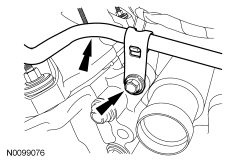
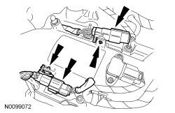
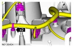
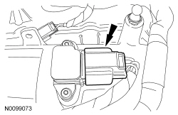
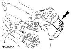
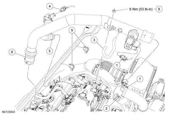
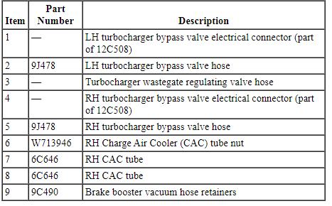
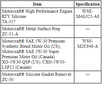
- Disconnect the LH turbocharger bypass valve electrical connector.
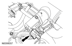
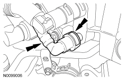
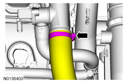
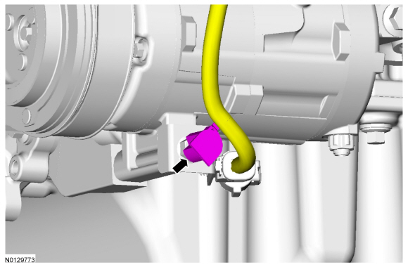
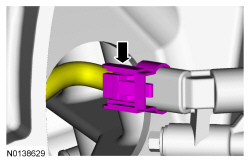
- Disconnect the LH turbocharger bypass valve hose from the RH Charge Air Cooler (CAC) tube.

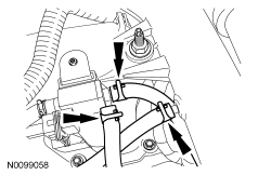
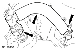
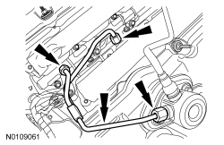
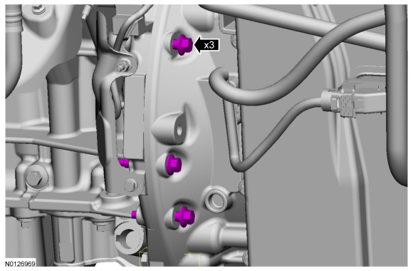
- NOTE: Mark the location of each hose for installation.
Disconnect the 3 turbocharger wastegate hoses.
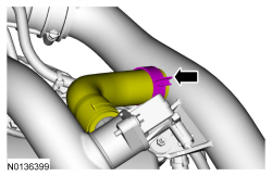
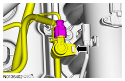
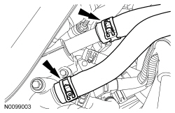
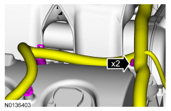
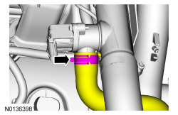
- Disconnect the RH turbocharger bypass valve electrical connector.

- Disconnect the RH turbocharger bypass valve hose from the RH turbocharger intake tube.
- NOTICE: The compression limiter bushing may fall out of the
mounting bracket grommet on the Charge Air Cooler (CAC) tube during service.
Make sure the bushing is in place when reinstalling the tube or damage to
the tube may occur.
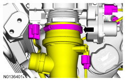
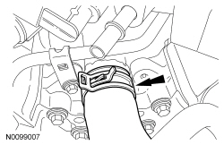
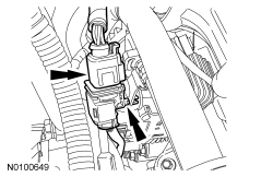
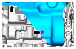
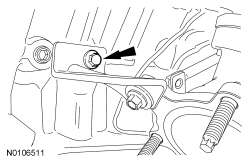
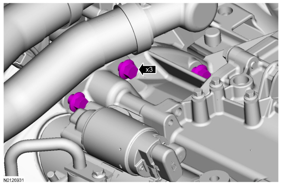
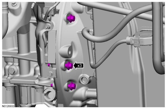
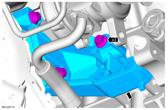
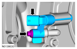
Remove the RH CAC tube nut from the intake manifold.
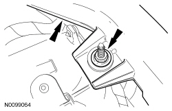
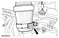
- Loosen the clamp for the RH CAC tube.

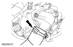
- Loosen the clamp and remove the RH CAC tube from the RH turbocharger.

- If equipped, remove the noise generator. For additional information, refer to Intake Air System Components - Exploded View in Section 303-12.
- Loosen the clamp and position CAC outlet pipe-to-Throttle Body (TB) aside.
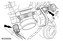
- Disconnect the Throttle Position (TP) sensor and electronic TB electrical connectors.

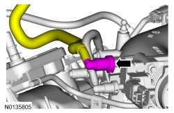
- Disconnect the quick connect coupling from the intake manifold. For additional information, refer to Section 310-00.

- Disconnect the quick connect coupling Evaporative Emission (EVAP) tube from the intake manifold. For additional information, refer to Section 310-00.

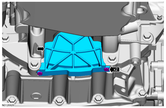
- Detach the EVAP purge valve from the intake manifold.
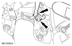
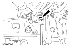
- Remove the fuel tube-to-engine front cover bracket bolt and position the fuel tube aside.
- Disconnect the PCV tube quick connect coupling from the intake manifold. For additional information, refer to Section 310-00.
- Detach and disconnect the 2 fuel injector wiring harness electrical connectors.
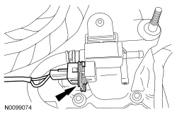
- Disconnect the Manifold Absolute Pressure (MAP)/Intake Air Temperature 2 (IAT2) sensor electrical connector.

- Disconnect the turbocharger wastegate regulating valve electrical connector.

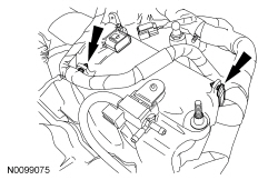
- Detach the 2 wire harness-to-intake manifold retainers.

- Detach the 2 wire harness retainers from the LH valve cover stud bolt.

- Detach the 2 wire harness retainers from the LH valve cover.

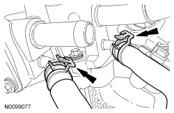
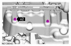
- Disconnect the 2 coolant heater hoses from the intake manifold.
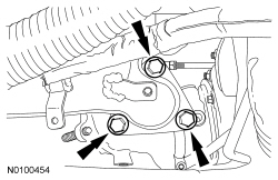
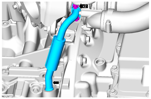
- Disconnect the 2 turbocharger coolant hoses from the intake manifold.

- Disconnect the lower radiator hose from the thermostat housing.

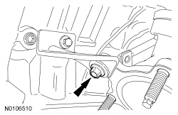
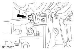
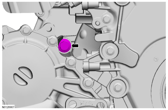
- Remove the bolt and ground wire from the engine front cover.

- Disconnect the upper radiator hose at the intake manifold and position the hose aside.

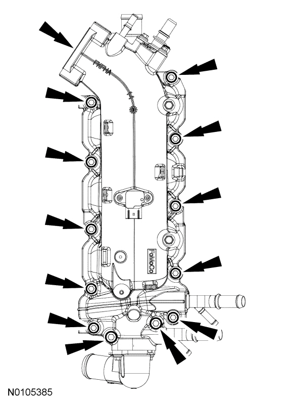
- NOTE: Note the routing of the 2 fuel rail wiring harnesses for
installation.
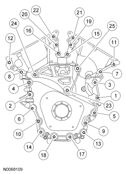
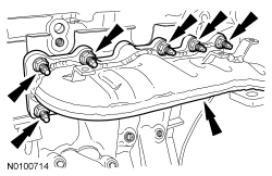
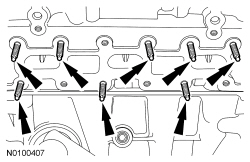
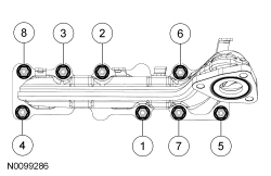
Remove the 12 bolts and the intake manifold.
- Remove and discard the intake manifold, coolant crossover and thermostat housing gaskets.
- Clean and inspect all sealing surfaces.
Installation
- NOTICE: If the engine is repaired or replaced because of upper
engine failure, typically including valve or piston damage, check the intake
manifold for metal debris. If metal debris is found, install a new intake
manifold. Failure to follow these instructions can result in engine damage.
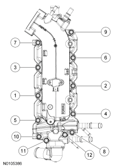
NOTE: Make sure the fuel rail wiring harnesses are routed correctly.
NOTE: Installing the 2 long bolts first will aid in installing the intake manifold.
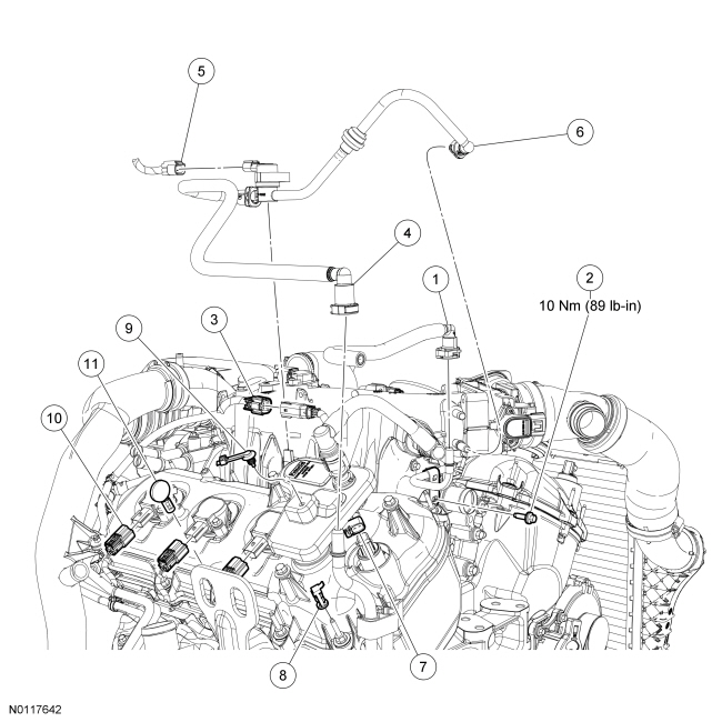
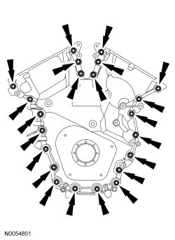
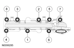
Using new intake manifold, coolant crossover and thermostat housing gaskets, install the intake manifold and the 12 bolts. Tighten in the sequence shown in 2 stages.- Stage 1: Tighten to 10 Nm (89 lb-in).
- Stage 2: Tighten an additional 45 degrees.
- Connect the upper radiator hose to the intake manifold.
- Install the ground wire and bolt to the engine front cover.
- Tighten to 10 Nm (89 lb-in).
- Connect the lower radiator hose to the thermostat housing.
- Connect the 2 turbocharger coolant hoses to the intake manifold.
- Connect the 2 coolant heater hoses to the intake manifold.

- Attach the 2 wire harness retainers to the LH valve cover.
- Attach the 2 wire harness retainers to the LH valve cover stud bolt.
- Attach the 2 wire harness-to-intake manifold retainers.
- Connect the turbocharger wastegate regulating valve electrical connector.
- Connect the MAP / IAT2 sensor electrical connector.
- Connect and attach the 2 fuel injector wiring harness electrical connectors.

- Connect the PCV tube quick connect coupling to the intake manifold. For additional information, refer to Section 310-00.

- Position the fuel tube and install the fuel tube-to-engine front cover
bracket bolt.
- Tighten to 10 Nm (89 lb-in).

- Attach the EVAP purge valve to the intake manifold.

- Connect the quick connect coupling EVAP tube to the intake manifold. For additional information, refer to Section 310-00.
- Connect the quick connect coupling to the intake manifold. For additional information, refer to Section 310-00.
- Connect the TP sensor and electronic TB electrical connectors.
- NOTE: Align the index marks for the CAC outlet pipe.
Position CAC outlet pipe on the TB and tighten the clamp.
- Tighten to 5 Nm (44 lb-in).

- If equipped, install the noise generator. For additional information, refer to Intake Air System Components - Exploded View in Section 303-12.
- NOTE: Align the index marks for the RH CAC tube.
Install the RH CAC tube to the RH turbocharger and tighten the clamp.
- To install, tighten to 5 Nm (44 lb-in).
- NOTE: Align the index marks for the RH CAC tube.
Install the RH CAC tube and tighten the clamp.
- To install, tighten to 5 Nm (44 lb-in).
- NOTICE: The compression limiter bushing may fall out of the
mounting bracket grommet on the Charge Air Cooler (CAC) tube during service.
Make sure the bushing is in place when reinstalling the tube or damage to
the tube may occur.
Install the RH CAC tube and the RH CAC tube nut to the intake manifold.
- Tighten to 6 Nm (53 lb-in).

- Connect the RH turbocharger bypass valve hose to the RH turbocharger intake tube.

- Connect the RH turbocharger bypass valve electrical connector.
- Connect the 3 turbocharger wastegate hoses.

- Connect the LH turbocharger bypass valve to the RH Charge Air Cooler (CAC) tube.
- Connect the LH turbocharger bypass valve electrical connector.

- Install the ACL outlet pipe. For additional information, refer to Section 303-12.
- Fill and bleed the cooling system. For additional information, refer to Section 303-03.
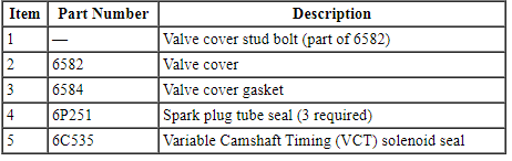
Valve Cover - LH
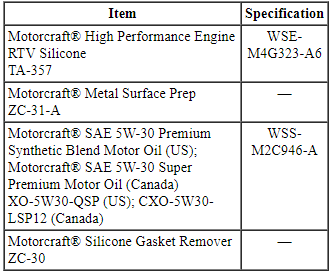
Material
Valve Cover - LH (View 1 of 4)
Valve Cover - LH (View 2 of 4)
Valve Cover - LH (View 3 of 4)
Valve Cover - LH (View 4 of 4)
Removal
NOTICE: During engine repair procedures, cleanliness is extremely important. Any foreign material, including any material created while cleaning gasket surfaces that enters the oil passages, coolant passages or the oil pan, may cause engine failure.
NOTICE: Whenever turbocharger air intake system components are removed, always cover open ports to protect from debris. It is important that no foreign material enter the system. The turbocharger compressor vanes are susceptible to damage from even small particles. All components should be inspected and cleaned, if necessary, prior to installation or reassembly.
- Release the fuel system pressure. For additional information, refer to Section 310-00.
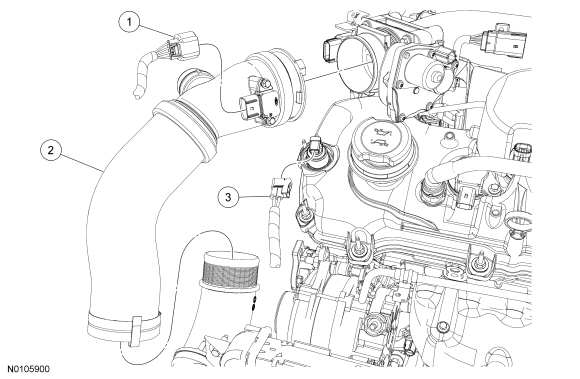
- Disconnect the Turbocharger Boost Pressure (TCBP)/Charge Air Cooler Temperature (CACT) sensor electrical connector.
- If equipped, remove the noise generator. For additional information, refer to Intake Air System Components - Exploded View in Section 303-12.
- Loosen the 2 clamps and remove the Charge Air Cooler (CAC) outlet pipe.
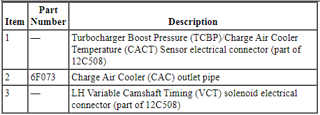
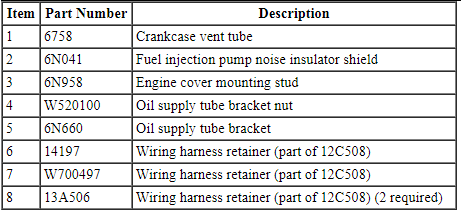
- Disconnect the 2 quick connect couplings and remove the crankcase vent tube. For additional information, refer to Section 310-00.
- Remove the fuel injection pump noise insulator shield.
- Remove the oil level indicator.
- Remove the intake manifold. For additional information, refer to Intake Manifold in this section.
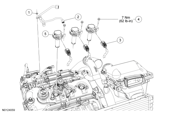
- Remove the nut for the high-pressure fuel tube from the LH valve cover stud bolt.

- NOTE: To release the fuel pressure in the high-pressure fuel
tubes, wrap the flare nut with a shop towel to absorb any residual fuel
pressure during the loosening of the flare nuts.
Remove the high-pressure fuel tube flare nut from the fuel injection pump. Remove the 2 high-pressure fuel tube flare nuts from the fuel rails and remove the high-pressure fuel tube assembly.
- Remove the fuel injection pump. For additional information, refer to Section 303-04B.
- Disconnect the LH Variable Camshaft Timing (VCT) solenoid electrical connector.
- Remove the engine cover mounting stud from the LH valve cover stud bolt.
- Detach all of the wiring harness retainers from the LH valve cover stud bolts.
- Remove the nut and the oil supply tube bracket from the LH valve cover stud bolt.
- Disconnect the 3 LH ignition coil-on-plug electrical connectors.
- NOTE: When removing the ignition coil-on-plugs, a slight twisting
motion will break the seal and ease removal.
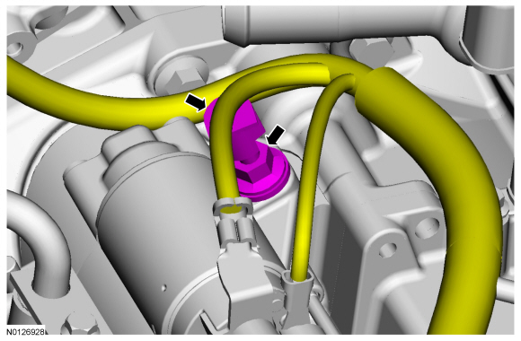
Remove the 3 bolts and the 3 LH ignition coil-on-plugs.
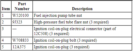
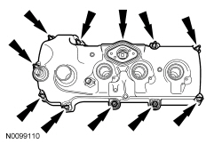
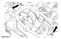
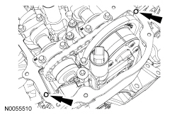
- Loosen the 10 stud bolts and remove the LH valve cover.
- Discard the gasket.
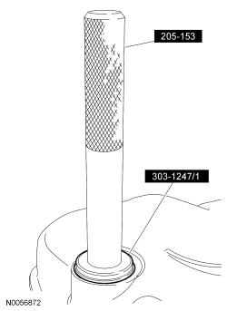
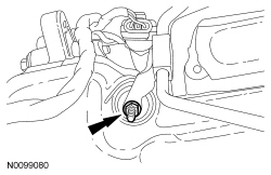
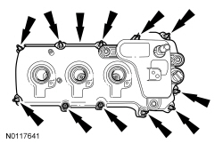
- NOTE: VCT solenoid seal removal shown, spark plug tube seal
removal similar.
Inspect the VCT solenoid seals and the spark plug tube seals. Remove any damaged seals.
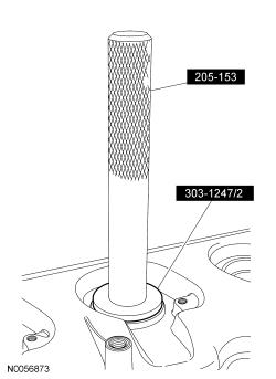
- Using the VCT Spark Plug Tube Seal Remover and Handle, remove the seal(s).
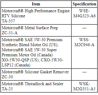
- Clean the valve cover, cylinder head and engine front cover sealing surfaces with metal surface prep.
Installation
- NOTE: Installation of new seals is only required if damaged seals
were removed during disassembly of the engine.
NOTE: Spark plug tube seal installation shown, VCT solenoid seal installation similar.
Using the VCT Spark Plug Tube Seal Installer and Handle, install new VCT solenoid and/or spark plug tube seals.
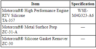
- NOTICE: Failure to use the correct Motorcraft High
Performance Engine RTV Silicone may cause the engine oil to foam excessively
and result in serious engine damage.
NOTE: If the valve cover is not installed and the fasteners tightened within 4 minutes, the sealant must be removed and the sealing area cleaned. To clean the sealing area, use silicone gasket remover and metal surface prep. Failure to follow these instructions can cause future oil leakage.
Apply an 8 mm (0.31 in) bead of Motorcraft High Performance Engine RTV Silicone to the engine front cover-to-LH cylinder head joints.
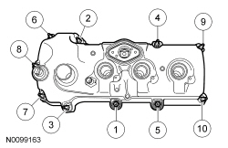
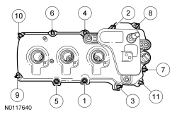
- Using a new gasket, install the LH valve cover and tighten the 10 stud
bolts.
- Tighten in the sequence shown to 10 Nm (89 lb-in).
- Install 3 LH ignition coil-on-plugs and the 3 bolts.
- Tighten to 7 Nm (62 lb-in).
- Connect the 3 LH ignition coil-on-plug electrical connectors.
- Install the oil supply tube bracket on the LH valve cover stud bolt and
install the nut.
- Tighten to 8 Nm (71 lb-in).
- Attach all of the wiring harness retainers to the LH valve cover and stud bolts.
- Install the engine cover mounting stud to the LH valve cover stud bolt.
- Tighten to 6 Nm (53 lb-in).
- Connect the LH VCT solenoid electrical connector.
- Install the fuel injection pump. For additional information, refer to Section 303-04B.
- NOTE: To install, apply clean engine oil to the threads of the 3
high-pressure fuel tube flare nuts.
Install the high-pressure fuel tube and tighten the 3 flare nuts in the following 3 stages.
- Stage 1: Tighten to 32 Nm (24 lb-ft).
- Stage 2: Wait 10 minutes to minimize pre-stress.
- Stage 3: Tighten to 32 Nm (24 lb-ft).

- Install the high-pressure fuel tube bracket nut.
- Tighten to 8 Nm (71 lb-in).
- Install the intake manifold. For additional information, refer to Intake Manifold in this section.
- Install the oil level indicator.
- Install the fuel injection pump noise insulator shield.
- Install the crankcase vent tube and connect the 2 quick connect couplings. For additional information, refer to Section 310-00.
- NOTE: Align the index marks for the CAC outlet pipe.
Install the CAC outlet pipe and tighten the 2 clamps.
- Tighten to 5 Nm (44 lb-in).
- If equipped, install the noise generator. For additional information, refer to Intake Air System Components - Exploded View in Section 303-12.
- Connect the TCBP / CACT sensor electrical connector.
Valve Cover - RH
Material
Valve Cover - RH (View 1 of 4)
Valve Cover - RH (View 2 of 4)
Valve Cover - RH (View 3 of 4)
Valve Cover - RH (View 4 of 4)
Removal
NOTICE: During engine repair procedures, cleanliness is extremely important. Any foreign material, including any material created while cleaning gasket surfaces that enters the oil passages, coolant passages or the oil pan, may cause engine failure.
NOTICE: Whenever turbocharger air intake system components are removed, always cover open ports to protect from debris. It is important that no foreign material enter the system. The turbocharger compressor vanes are susceptible to damage from even small particles. All components should be inspected and cleaned, if necessary, prior to installation or reassembly.
- Release the fuel system pressure. For additional information, refer to Section 310-00.
- Remove the Air Cleaner (ACL) outlet pipe. For additional information, refer to Section 303-12.
- Disconnect the LH turbocharger bypass valve electrical connector.
- Disconnect the turbocharger bypass valve hose from the RH Charge Air Cooler (CAC) tube.
- Remove the turbocharger wastegate regulating valve hose from the RH CAC tube.
- Disconnect the RH turbocharger bypass valve electrical connector.
- Disconnect the RH turbocharger bypass valve hose from the RH turbocharger intake tube.
- NOTICE: The compression limiter bushing may fall out of the
mounting bracket grommet on the Charge Air Cooler (CAC) tube during service.
Make sure the bushing is in place when reinstalling the tube or damage to
the tube may occur.
Remove the RH CAC tube nut from the intake manifold.
- Loosen the clamp and remove the RH CAC tube.
- Loosen the clamp and remove the RH CAC tube.
- Detach the 2 brake booster vacuum hose retainers from the strut tower brace and position aside.
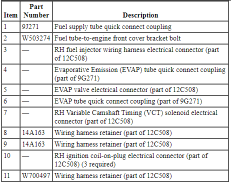
- Disconnect the fuel supply tube. For additional information, refer to Section 310-00.
- Remove the fuel tube-to-engine front cover bracket bolt and position the fuel tube aside.
- Disconnect the RH fuel injector wiring harness electrical connector.
- Disconnect the Evaporative Emission (EVAP) tube quick connect coupling. For additional information, refer to Section 310-00.
- Disconnect the EVAP valve electrical connector and detach from the intake manifold.
- Disconnect the quick connect coupling from the intake manifold and remove the EVAP tube assembly. For additional information, refer to Section 310-00.
- Disconnect the 2 quick connect couplings and remove the PCV tube. For additional information, refer to Section 310-00.
- Disconnect the RH Variable Camshaft Timing (VCT) solenoid electrical connector and detach the 2 wiring harness retainers.
- Disconnect the 3 RH ignition coil-on-plugs electrical connectors.
- Detach all of the wiring harness retainers from the RH valve cover and stud bolts position aside.
- NOTE: When removing the ignition coil-on-plugs, a slight twisting
motion will break the seal and ease removal.
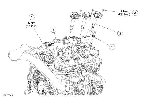
Remove the 3 bolts and the 3 RH ignition coil-on-plugs.
- Loosen the clamp and remove the RH turbocharger intake tube from the RH turbocharger intake pipe.
- NOTICE: The compression limiter bushing may fall out of the
mounting bracket grommet on the turbocharger intake tube during service.
Make sure the bushing is in place when reinstalling the tube or damage to
the tube may occur.
Remove the nut from the RH valve cover stud bolt and position the RH turbocharger intake tube off the RH valve cover stud bolt.
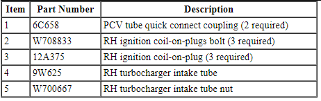
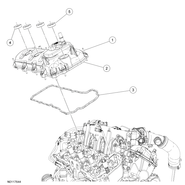
- Loosen the 11 stud bolts and remove the RH valve cover.
- Discard the gasket.
- NOTE: VCT solenoid seal removal shown, spark plug tube seal
removal similar.
Inspect the VCT solenoid seals and the spark plug tube seals. Remove any damaged seals.
- Using the VCT Spark Plug Tube Seal Remover and Handle, remove the seal(s).

- Clean the valve cover, cylinder head and engine front cover sealing surfaces with metal surface prep.
Installation
- NOTE: Installation of new seals is only required if damaged seals
were removed during disassembly of the engine.
NOTE: Spark plug tube seal installation shown, VCT solenoid seal installation similar.
Using the VCT Spark Plug Tube Seal Installer and Handle, install new VCT solenoid and/or spark plug tube seals.

- NOTICE: Failure to use Motorcraft High Performance Engine RTV
Silicone may cause the engine oil to foam excessively and result in serious
engine damage.
NOTE: If the valve cover is not installed and the fasteners tightened within 4 minutes, the sealant must be removed and the sealing area cleaned. To clean the sealing area, use silicone gasket remover and metal surface prep. Failure to follow this procedure can cause future oil leakage.
Apply an 8 mm (0.31 in) bead of Motorcraft High Performance Engine RTV Silicone to the engine front cover-to-RH cylinder head joints.
- Using a new gasket, install the RH valve cover and tighten the 11 stud
bolts.
- Tighten in the sequence shown to 10 Nm (89 lb-in).
- NOTICE: The compression limiter bushing may fall out of the
mounting bracket grommet on the turbocharger intake tube during service.
Make sure the bushing is in place when reinstalling the tube or damage to
the tube may occur.
Position the RH turbocharger intake tube and install the nut to the RH valve cover stud bolt.
- Tighten to 6 Nm (53 lb-in).
- NOTE: Align the index marks for the RH turbocharger intake tube.
Install the RH turbocharger intake tube to the RH turbocharger intake pipe and tighten the clamp.
- Tighten to 5 Nm (44 lb-in).
- Install 3 RH ignition coil-on-plugs and the 3 bolts.
- Tighten to 7 Nm (62 lb-in).
- Attach all of the wiring harness retainers to the RH valve cover and stud bolts.
- Connect the 3 RH ignition coil-on-plug electrical connectors.
- Connect the RH VCT solenoid electrical connector and attach the 2 wiring harness retainers.
- Install the PCV tube and connect the 2 quick connect couplings. For additional information, refer to Section 310-00.
- Install the EVAP tube assembly and connect the quick connect coupling to the intake manifold. For additional information, refer to Section 310-00.
- Connect the EVAP valve electrical connector and attach to the intake manifold.
- Connect the EVAP tube quick connect coupling. For additional information, refer to Section 310-00.
- Connect the RH fuel injector wiring harness electrical connector.
- Position the fuel tube and install the fuel tube-to-engine front cover
bracket bolt.
- Tighten to 10 Nm (89 lb-in).
- Connect the fuel supply tube. For additional information, refer to Section 310-00.
- Attach the 2 brake booster vacuum hose retainers to the strut tower brace.
- NOTE: Align the index marks for the RH CAC tube.
Install the RH CAC tube to the RH turbocharger and tighten the clamp.
- Tighten to 5 Nm (44 lb-in).
- NOTE: Align the index marks for the RH CAC tube.
Install the RH CAC tube and tighten the clamp.
- Tighten to 5 Nm (44 lb-in).
- NOTICE: The compression limiter bushing may fall out of the
mounting bracket grommet on the Charge Air Cooler (CAC) tube during service.
Make sure the bushing is in place when reinstalling the tube or damage to
the tube may occur.
Install the RH CAC tube and turbocharger intake tube as an assembly and install the RH CAC tube nut to the intake manifold.
- Tighten to 6 Nm (53 lb-in).
- Connect the RH turbocharger bypass valve hose to the RH turbocharger intake tube.
- Connect the RH turbocharger bypass valve electrical connector.
- Install the turbocharger wastegate regulating valve hose to the RH CAC tube.
- Connect the turbocharger bypass valve hose to the RH CAC tube.
- Connect the LH turbocharger bypass valve electrical connector.
- Install the ACL outlet pipe. For additional information, refer to Section 303-12.
Crankshaft Pulley
Special Tool(s)
Material
Removal
- Remove the accessory drive belt. For additional information, refer to Section 303-05.
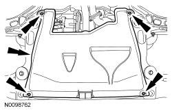
- If equipped, remove the 4 retainers and the underbody shield.

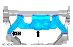
- If equipped, remove the 10 bolts and the skid plate.
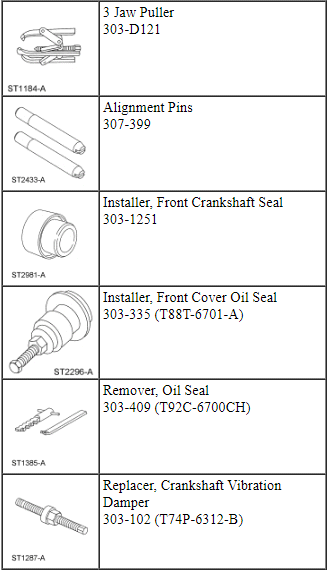
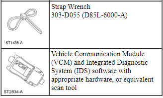
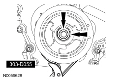
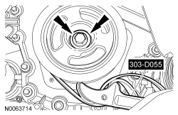
- Using the Strap Wrench, remove the crankshaft pulley bolt and washer.
- Discard the bolt.

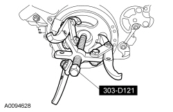
- Using the 3 Jaw Puller, remove the crankshaft pulley.

Installation
- Lubricate the crankshaft front seal inner lip with clean engine oil.
- NOTE: Lubricate the outside diameter sealing surfaces with clean
engine oil.
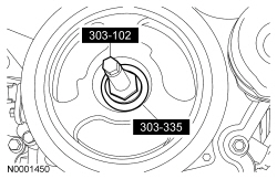
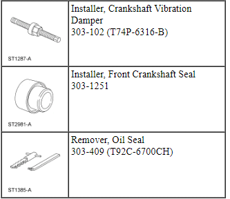
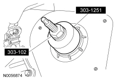
Using the Front Cover Oil Seal Installer and Crankshaft Vibration Damper Replacer, install the crankshaft pulley.
- Using the Strap Wrench, install the crankshaft pulley washer and new
bolt and tighten in 4 stages.
- Stage 1: Tighten to 120 Nm (89 lb-ft).
- Stage 2: Loosen one full turn.
- Stage 3: Tighten to 50 Nm (37 lb-ft).
- Stage 4: Tighten an additional 90 degrees.

- If equipped, install the skid plate and the 10 bolts.
- Tighten to 70 Nm (52 lb-ft).

- If equipped, install the underbody shield and the 4 retainers.

- Install the accessory drive belt. For additional information, refer to Section 303-05.
- After completing the repairs, use the scan tool to perform the Misfire Monitor Neutral Profile Correction procedure following the on-screen instructions.
Crankshaft Front Seal
Special Tool(s)
Material
Removal
- With the vehicle in NEUTRAL, position it on a hoist. For additional information, refer to Section 100-02.
- Remove the crankshaft pulley. For additional information, refer to Crankshaft Pulley in this section.
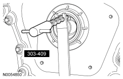
- Using the Oil Seal Remover, remove and discard the crankshaft front
seal.
- Clean all sealing surfaces with metal surface prep.
Installation
- NOTE: Apply clean engine oil to the crankshaft front seal bore in
the engine front cover.
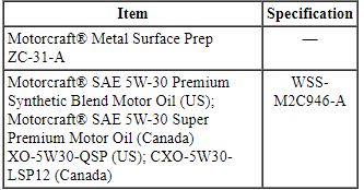
Using the Front Crankshaft Seal Installer and Crankshaft Vibration Damper Installer, install a new crankshaft front seal.

- Install the crankshaft pulley. For additional information, refer to Crankshaft Pulley in this section.
Flexplate
Special Tool(s)
Removal
- With the vehicle in NEUTRAL, position it on a hoist. For additional information, refer to Section 100-02.
- Remove the transaxle. For additional information, refer to Section 307-01A.
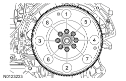
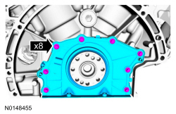
- Remove the 8 bolts and the flexplate.
Installation
- NOTE: One of the 8 flexplate holes are offset so the flexplate
can only be installed in one position.
Install the flexplate and the 8 bolts.
- Tighten in the sequence shown to 80 Nm (59 lb-ft).
- Install the transaxle. For additional information, refer to Section 307-01A.
- Using the scan tool, perform the Misfire Monitor Neutral Profile Correction procedure, following the on-screen instructions.
Engine Front Cover
Special Tool(s)
Material
Removal
NOTICE: During engine repair procedures, cleanliness is extremely important. Any foreign material, including any material created while cleaning gasket surfaces that enters the oil passages, coolant passages or the oil pan, may cause engine failure.
- With the vehicle in NEUTRAL, position it on a hoist. For additional information, refer to Section 100-02.
- Disconnect the LH Heated Oxygen Sensor (HO2S) electrical connector.
- Detach the HO2S connector retainer from the bracket.
- Remove the LH and RH valve cover. For additional information, refer to Valve Cover - LH and Valve Cover - RH in this section.
- If equipped, remove the 4 retainers and the underbody shield.
- If equipped, remove the 10 bolts and the skid plate.

- Remove the RH inner fender splash shield. For additional information, refer to Section 501-02.
- Remove the accessory drive belt and tensioner. For additional information, refer to Section 303-05.
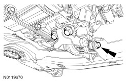
- Loosen the rear roll restrictor bolt.

- Remove the 2 bolts and the rear roll restrictor bracket.
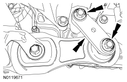
- Remove the front roll restrictor bolt.
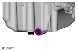
- Remove the oil pan drain plug and drain the engine oil.
- Install the drain plug and tighten to 27 Nm (20 lb-ft).
- Using the Strap Wrench, remove the crankshaft bolt and washer.
- Discard the bolt.
- Using the 3 Jaw Puller, remove the crankshaft pulley.
- Using the Oil Seal Remover, remove and discard the crankshaft front seal.

- Remove the engine mount. For additional information, refer to Engine Mount in this section.
- NOTE: Only use hand tools to remove the studs.
Remove the 2 engine mount studs.

- Detach the RH Heated Oxygen Sensor (HO2S) electrical connector from the
bracket.
- Remove the stud bolt and the bracket.
- Using the floor jack, raise the engine slightly.
- Remove the 2 upper engine mount bracket bolts.

- Using the floor jack, lower the engine slightly.
- Loosen the lower engine mount bracket bolt and remove the engine mount bracket and bolt as an assembly.

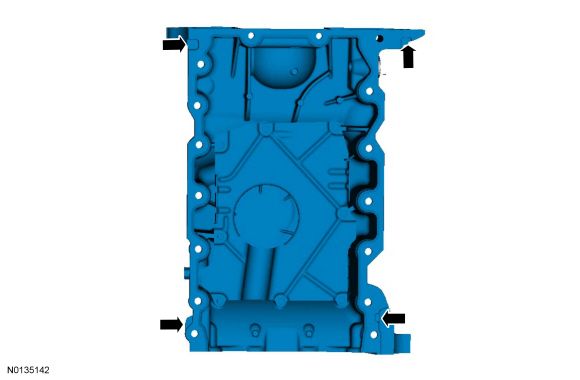
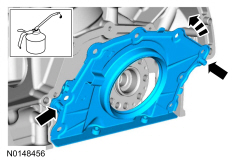
- Remove the 22 engine front cover bolts.
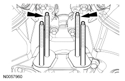
- Install 6 of the engine front cover bolts (finger tight) into the 6
threaded holes in the engine front cover.
- Tighten the bolts one turn at a time in a crisscross pattern until the engine front cover-to-cylinder block seal is released.
- Remove the engine front cover.
Installation
- NOTICE: Only use a 3M Roloc Bristle Disk (2 in white, part
number 07528), to clean the engine front cover. Do not use metal scrapers,
wire brushes or any other power abrasive disk to clean the engine front
cover.
Clean the engine front cover using a 3M Roloc Bristle Disk (2 in white, part number 07528) in a suitable tool turning at the recommended speed of 15,000 rpm.
- Thoroughly wash the engine front cover to remove any foreign material, including any abrasive particles created during the cleaning process.
- NOTICE: Place clean, lint free shop towels over exposed engine
cavities. Carefully remove the towels so foreign material is not dropped
into the engine. Any foreign material (including any material created while
cleaning gasket surfaces) that enters the oil passages or the oil pan, may
cause engine failure.
NOTICE: Do not use wire brushes, power abrasive discs or 3M Roloc Bristle Disk (2-in white, part number 07528) to clean the sealing surfaces of the engine block, cylinder heads, and oil pan. These tools cause contamination that can cause premature engine failure. Remove all traces of sealant, including any sealant from the inner surface of the cylinder block and cylinder head.
NOTE: Observe all warnings or cautions and follow all application directions contained on the packaging of the silicone gasket remover and the metal surface prep.
Clean the sealing surfaces of the cylinder heads, the cylinder block and the oil pan in the following sequence.- Remove any large deposits of silicone or gasket material with a plastic scraper.
- Apply silicone gasket remover, following package directions and allow to set for several minutes.
- Remove the silicone gasket remover with a plastic scraper. A second application of silicone gasket remover may be required if residual traces of silicone or gasket material remain.
- Apply metal surface prep, following package directions, to remove any remaining traces of oil or coolant and to prepare the surfaces to bond. Do not attempt to make the metal shiny. Some staining of the metal surfaces is normal.
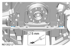
- Make sure the 2 locating dowel pins are seated correctly in the cylinder block.
- Install the Alignment Pins.
- NOTICE: Failure to use the correct RTV Silicone Sealant
(TA-357) may cause the engine oil to foam excessively and result in serious
engine damage.
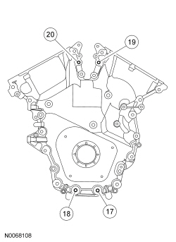
NOTE: The engine front cover and bolts 17, 18, 19 and 20 must be installed within 4 minutes of the initial sealant application. The remainder of the engine front cover bolts and the engine mount bracket bolts must be installed and tightened within 35 minutes of the initial sealant application. If the time limits are exceeded, the sealant must be removed, the sealing area cleaned and sealant reapplied. To clean the sealing area, use silicone gasket remover and metal surface prep. Follow the directions on the packaging. Failure to follow this procedure can cause future oil leakage.
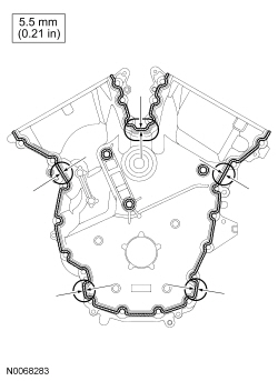
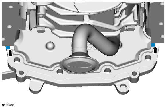
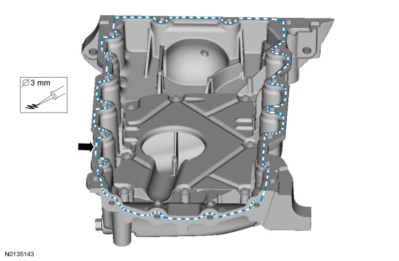
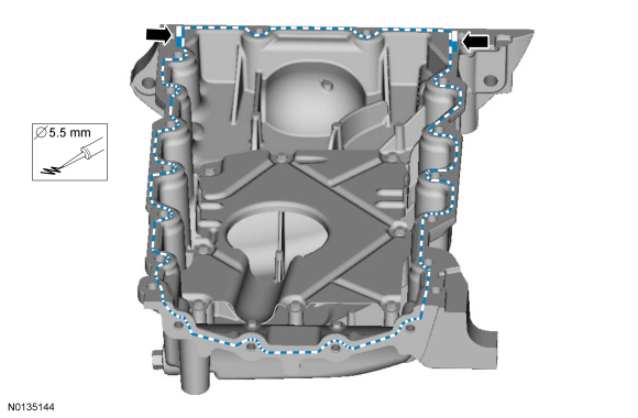
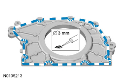
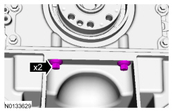
Apply a 3.0 mm (0.11 in) bead of RTV Silicone Sealant (TA-357) to the engine front cover sealing surfaces including the 3 engine mount bracket bosses.- Apply a 5.5 mm (0.21 in) bead of RTV Silicone Sealant (TA-357) to the oil pan-to-cylinder block joint and the cylinder head-to-cylinder block joint areas of the engine front cover in 5 places as indicated.
- NOTE: Make sure the 2 locating dowel pins are seated correctly in
the cylinder block.
Install the engine front cover and bolts 17, 18, 19 and 20.
- Tighten in sequence to 3 Nm (27 lb-in).
- Remove the Alignment Pins.
- Install the engine mount bracket and lower bolt.
- Do not tighten at this time.
- Using the floor jack, raise the engine slightly.
- Install the 2 upper engine mount bracket bolts.
- Do not tighten at this time.
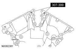
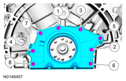
- Install the remaining engine front cover bolts. Tighten all of the
engine front cover bolts and engine mount bracket bolts in the sequence
shown in 2 stages:
- Stage 1: Tighten bolts 1 thru 22 to 10 Nm (89 lb-in) and bolts 23, 24 and 25 to 15 Nm (133 lb-in).
- Stage 2: Tighten bolts 1 thru 22 to 24 Nm (18 lb-ft) and bolts 23, 24 and 25 to 75 Nm (55 lb-ft).
- Install the HO2S connector bracket and stud bolt.
- Tighten to 10 Nm (89 lb-in).
- Attach the HO2S electrical connector.

- NOTICE: The thread sealer on the engine mount studs (including
new engine mount studs if applicable) must be cleaned off with a wire brush
and new Threadlock and Sealer applied prior to installing the engine mount
studs. Failure to follow this procedure may result in damage to the engine
mount studs or engine.
Install the engine mount studs in the following sequence.
- Clean the front cover engine mount stud holes with pressurized air to remove any foreign material.
- Clean all the thread sealer from the engine mount studs (old and new studs).
- Apply new Threadlock and Sealer to the engine mount stud threads.
- Install the 2 engine mount studs.
- Tighten to 20 Nm (177 lb-in).
- Install the engine mount. For additional information, refer to Engine Mount in this section.
- NOTE: Apply clean engine oil to the crankshaft front seal bore in
the engine front cover.
Using the Crankshaft Vibration Damper Replacer and Front Crankshaft Seal Installer, install a new crankshaft front seal.
- NOTE: Lubricate the outside diameter sealing surfaces with clean
engine oil.
Using the Crankshaft Vibration Damper Replacer and Front Cover Oil Seal Installer, install the crankshaft pulley.

- Using the Strap Wrench, install the crankshaft pulley washer and new
bolt and tighten in 4 stages.
- Stage 1: Tighten to 120 Nm (89 lb-ft).
- Stage 2: Loosen one full turn.
- Stage 3: Tighten to 50 Nm (37 lb-ft).
- Stage 4: Tighten an additional 90 degrees.
- NOTE: The bracket has keyed tabs to orient the roll restrictor.
Position the rear roll restrictor bracket with the keyed tabs aligned to the rear roll restrictor and install the bolts.
- Tighten to 103 Nm (76 lb-ft).
- Tighten the rear roll restrictor bolt to 103 Nm (76 lb-ft).
- Install the front roll restrictor bolt.
- Tighten to 103 Nm (76 lb-ft).

- Install the accessory drive belt tensioner and belt. For additional information, refer to Section 303-05.
- Install the RH inner fender splash shield. For additional information, refer to Section 501-02.
- If equipped, install the skid plate and 10 bolts.
- Tighten to 70 Nm (52 lb-ft).

- If equipped, install the underbody shield and the 4 retainers.

- Install the RH and LH valve covers. For additional information, refer to Valve Cover - RH and Valve Cover - LH in this section.
- Connect the LH HO2S electrical connector.
- Attach the HO2S connector retainer to the bracket.

- NOTICE: Do not expose the RTV Silicone Sealant to engine oil
for at least 90 minutes after installing the engine front cover. Failure to
follow this instruction may cause oil leakage.
Fill the engine with clean engine oil.
- After completing the repairs, use the scan tool to perform the Misfire Monitor Neutral Profile Correction procedure following the on-screen instructions.
Timing Drive Components
Special Tool(s)
Removal
NOTICE: During engine repair procedures, cleanliness is extremely important. Any foreign material, including any material created while cleaning gasket surfaces, that enters the oil passages, coolant passages or the oil pan may cause engine failure.
- Remove the engine front cover. For additional information, refer to Engine Front Cover in this section.
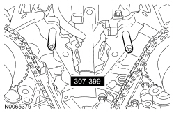
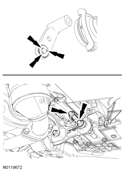
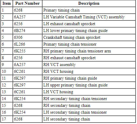
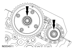
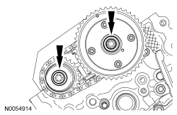
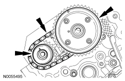
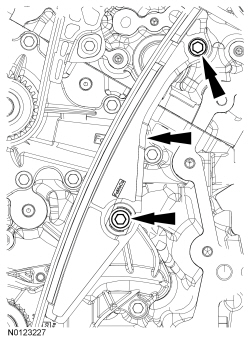
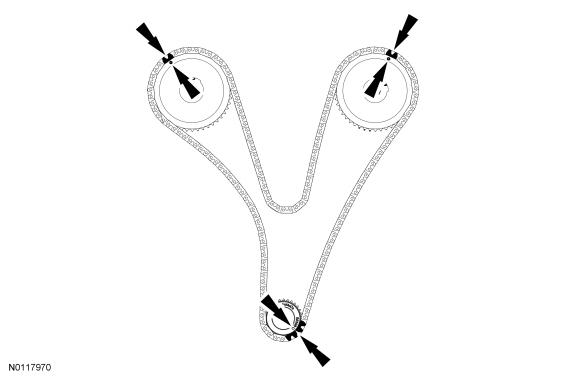
- Rotate the crankshaft clockwise and align the timing marks on the Variable Camshaft Timing (VCT) assemblies as shown.
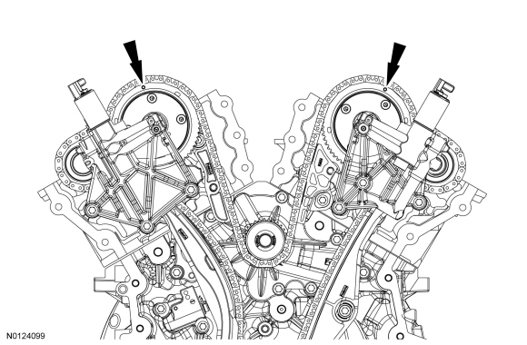
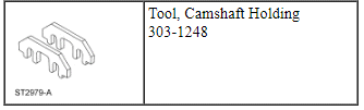
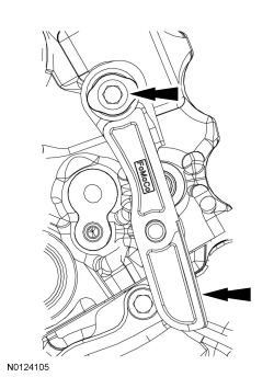
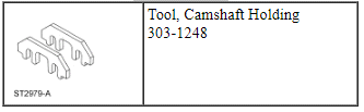
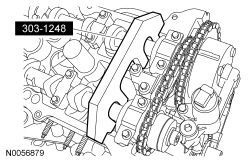
- NOTE: The Camshaft Holding Tool will hold the camshafts in the
Top Dead Center (TDC) position.
Install the Camshaft Holding Tool onto the flats of the LH camshafts.
- NOTE: The Camshaft Holding Tool will hold the camshafts in
the TDC position.
Install the Camshaft Holding Tool onto the flats of the RH camshafts.

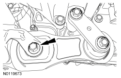
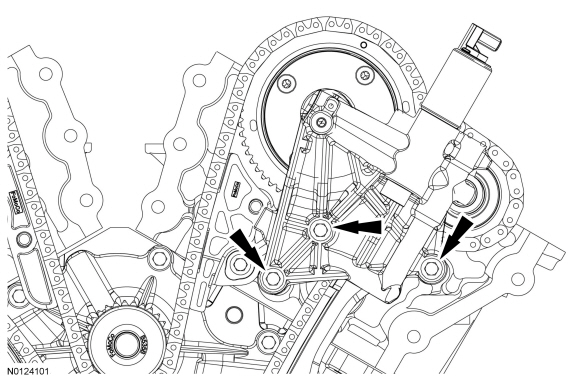
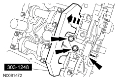
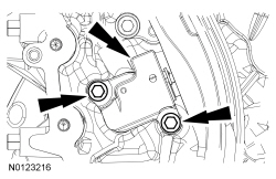
- Remove the 3 bolts and the RH VCT housing.

- Remove the 3 bolts and the LH VCT housing.
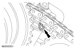
NOTE: The following 3 steps are for primary timing chains when the colored links are not visible.
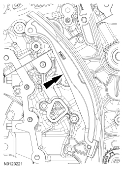
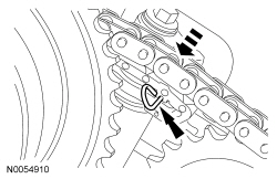
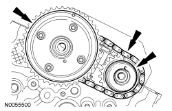
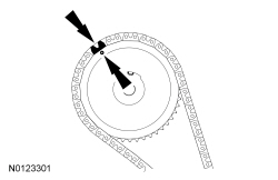
- Mark the timing chain link that aligns with the timing mark on the RH intake VCT assembly as shown.

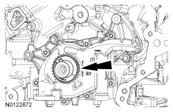
- Mark the timing chain link that aligns with the timing mark on the LH intake VCT assembly as shown.
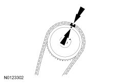
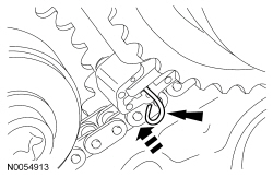
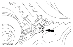
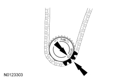
- NOTE: The crankshaft sprocket timing mark should be between the 2
colored links.
Mark the 2 timing chain links that align with the timing mark on the crankshaft sprocket as shown.

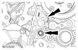
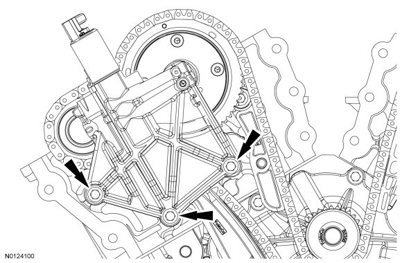
- Remove the 2 bolts and the primary timing chain tensioner.

- Remove the primary timing chain tensioner arm.
- Remove the 2 bolts and the lower LH primary timing chain guide.

- Remove the primary timing chain.

- Remove the crankshaft timing chain sprocket.
- Remove the bolt and the upper LH primary timing chain guide.
- Compress the LH secondary timing chain tensioner and install a suitable lockpin to retain the tensioner in the collapsed position.
- NOTE: The VCT bolt and the exhaust camshaft bolt must be
discarded and new ones installed. However, the exhaust camshaft washer is
reusable.
Remove and discard the LH VCT assembly bolt and the LH exhaust camshaft sprocket bolt.
- Remove the LH VCT assembly, secondary timing chain and the LH exhaust camshaft sprocket as an assembly.
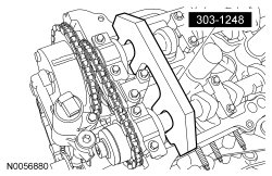
- NOTE: It is necessary to tilt the Camshaft Holding Tool toward
the rear of the engine to access the rearmost secondary timing chain
tensioner bolt.
Remove the 2 bolts and the LH secondary timing chain tensioner.
- Compress the RH secondary timing chain tensioner and install a suitable lockpin to retain the tensioner in the collapsed position.
- NOTE: The VCT bolt and the exhaust camshaft bolt must be
discarded and new ones installed. However, the exhaust camshaft washer is
reusable.
Remove and discard the RH VCT assembly bolt and the RH exhaust camshaft sprocket bolt.
- Remove the RH VCT assembly, secondary timing chain and the RH exhaust camshaft sprocket as an assembly.
- NOTE: It is necessary to tilt the Camshaft Holding Tool toward
the rear of the engine to access the rearmost secondary timing chain
tensioner bolt.
Remove the 2 bolts and the RH secondary timing chain tensioner.

- Remove the bolt and the RH timing chain guide.
Installation
- Install the RH timing chain guide and bolt.
- Tighten to 10 Nm (89 lb-in).

- NOTE: It is necessary to tilt the Camshaft Holding Tool toward
the rear of the engine to access the rearmost secondary timing chain
tensioner bolt.
Install the RH secondary timing chain tensioner and the 2 bolts.
- Tighten to 10 Nm (89 lb-in).
- Assemble the RH VCT assembly, the RH exhaust camshaft sprocket and the
RH secondary timing chain.
- Align the colored links with the timing marks.
- Position the RH secondary timing assembly onto the camshafts.
- Install the new VCT bolt and new exhaust camshaft bolt and the original
washer. Tighten in 4 stages.
- Stage 1: Tighten to 40 Nm (30 lb-ft).
- Stage 2: Loosen one full turn.
- Stage 3: Tighten to 10 Nm (89 lb-in).
- Stage 4: Tighten 90 degrees.

- Remove the lockpin from the RH secondary timing chain tensioner.
- NOTE: It is necessary to tilt the Camshaft Holding Tool toward
the rear of the engine to access the rearmost secondary timing chain
tensioner bolt.
Install the LH secondary timing chain tensioner and the 2 bolts.
- Tighten to 10 Nm (89 lb-in).

- Assemble the LH VCT assembly, the LH exhaust camshaft sprocket and the
LH secondary timing chain.
- Align the colored links with the timing marks.
- Position the LH secondary timing assembly onto the camshafts.
- Install the new VCT bolt and new exhaust camshaft bolt and the original
washer. Tighten in 4 stages.
- Stage 1: Tighten to 40 Nm (30 lb-ft).
- Stage 2: Loosen one full turn.
- Stage 3: Tighten to 10 Nm (89 lb-in).
- Stage 4: Tighten 90 degrees.

- Remove the lockpin from the LH secondary timing chain tensioner.
- Install the crankshaft timing chain sprocket.

- Install the upper LH primary timing chain guide and the bolt.
- Tighten to 10 Nm (89 lb-in).

- NOTE: The crankshaft sprocket timing mark should be between the 2
colored links.
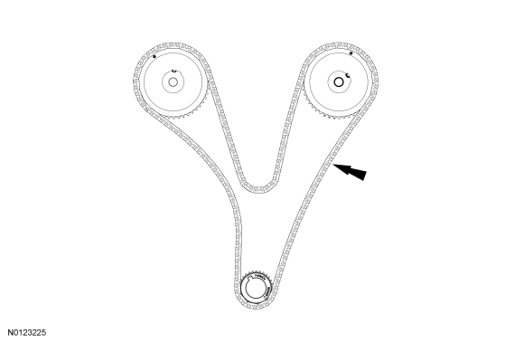
Install the primary timing chain with the colored links aligned with the timing marks on the VCT assemblies and the crankshaft sprocket.

- Install the lower LH primary timing chain guide and the 2 bolts.
- Tighten to 10 Nm (89 lb-in).

- Install the primary timing chain tensioner arm.

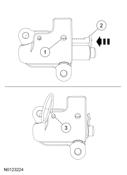
- Reset the primary timing chain tensioner.
- Release the ratchet detent.
- Using a soft-jawed vise, compress the ratchet plunger.
- Align the hole in the ratchet plunger with the hole in the tensioner housing and install a suitable lockpin.

- NOTE: It may be necessary to rotate the crankshaft slightly to
remove slack from the timing chain and install the tensioner.
Install the primary tensioner and the 2 bolts.
- Tighten to 10 Nm (89 lb-in).
- Remove the lockpin.
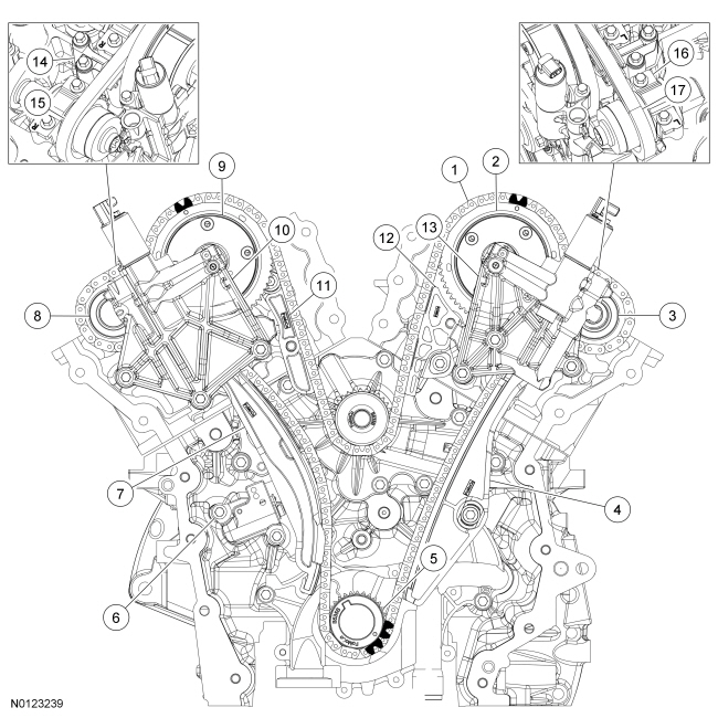
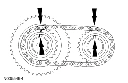
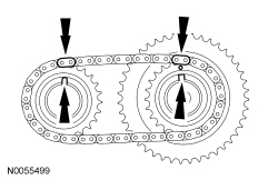
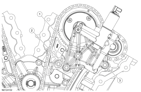
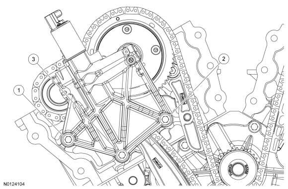
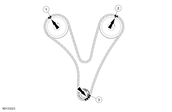
- As a post-check, verify correct alignment of all timing marks.
- There are 48 links between the RH intake VCT assembly colored link (1) and the LH intake VCT assembly colored link (2).
- There are 35 links between the LH intake VCT assembly colored link (2) and the 2 crankshaft sprockets colored links (3).

- Inspect the VCT housing seals for damage and replace as necessary.
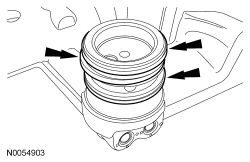
- NOTE: RH shown, LH similar.
NOTE: During removal, the O-ring seal may remain on the cylinder head. If so, remove the O-ring seal from the cylinder head, inspect the seal (replace as necessary) and install the O-ring seal on the VCT housing.
Inspect the VCT housing-to-cylinder head O-ring seals for damage and replace as necessary.

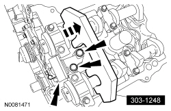
- NOTICE: Make sure the dowels on the Variable Camshaft Timing
(VCT) housing are fully engaged in the cylinder head prior to tightening the
bolts. Failure to follow this process will result in severe engine damage.
Install the LH VCT housing and the 3 bolts.
- Tighten in the sequence shown to 10 Nm (89 lb-in).
- NOTICE: Make sure the dowels on the Variable Camshaft Timing
(VCT) housing are fully engaged in the cylinder head prior to tightening the
bolts. Failure to follow this process will result in severe engine damage.
Install the RH VCT housing and the 3 bolts.
- Tighten in the sequence shown to 10 Nm (89 lb-in).
- Install the engine front cover. For additional information, refer to Engine Front Cover in this section.
Oil Cooler
Removal
- With the vehicle in NEUTRAL, position it on a hoist. For additional information, refer to Section 100-02.
- Drain the cooling system. For additional information, refer to Section 303-03.
- Remove the LH catalytic converter. For additional information, refer to Section 309-00.
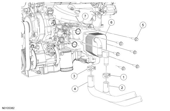
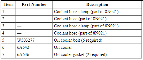
- Disconnect the 2 coolant hoses from the oil cooler.
- NOTICE: If metal or aluminum material is present
in the oil cooler, mechanical concerns exist. Failure to correct these
concerns may cause engine failure. To diagnose mechanical concerns, refer
to Section 303-00.
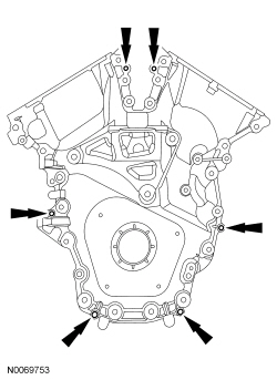
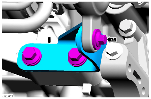
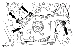
Remove the 6 bolts and the oil cooler.
- Discard the gaskets.
- Inspect the oil cooler.
- Clean and inspect all sealing surfaces.
Installation
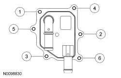
- Using new gaskets, install the oil cooler and the 6 bolts. Tighten in
the sequence shown.
- Tighten to 10 Nm (89 lb-in).
- Connect the 2 coolant hoses to the oil cooler.
- Install the LH catalytic converter. For additional information, refer to Section 309-00.
- Fill and bleed the cooling system. For additional information, refer to Section 303-03.
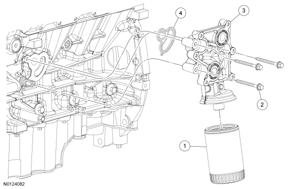
Oil Filter Adapter
Engines With Oil Cooler
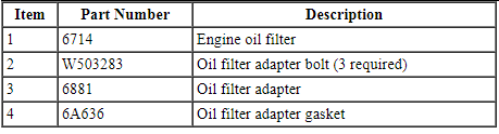
Engines Without Oil Cooler
Removal
- With the vehicle in NEUTRAL, position it on a hoist. For additional information, refer to Section 100-02.
- Remove and discard the engine oil filter.
- If equipped, remove the engine oil cooler. For additional information, refer to Oil Cooler in this section.
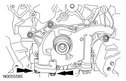
- Remove the 3 bolts and the oil filter adapter.
- Discard the gasket.
- Clean and inspect all sealing surfaces.
Installation
- Using a new gasket, install the oil filter adapter and the 3 bolts.
- Tighten to 10 Nm (89 lb-in) plus an additional 45 degrees.
- If equipped, install the engine oil cooler. For additional information, refer to Oil Cooler in this section.
- Install a new engine oil filter.
- Tighten to 5 Nm (44 lb-in) and then rotate an additional 180 degrees.
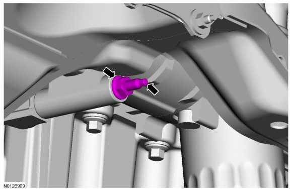
Engine Oil Pressure (EOP) Switch
Material
Removal and Installation
- With the vehicle in NEUTRAL, position it on a hoist. For additional information, refer to Section 100-02.
- If equipped, remove the oil cooler. For additional information, refer to Oil Cooler in this section.
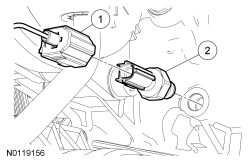
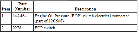
- Disconnect the Engine Oil Pressure (EOP) switch electrical connector.
- Remove the EOP switch.
- To install, tighten to 14 Nm (124 lb-in) plus an additional 180 degrees.
- To install, reverse the removal procedure.
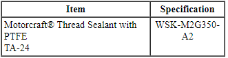
- Apply thread sealant with PTFE to the EOP switch threads prior to installation.
Exhaust Manifold - LH
Material
Removal
NOTICE: Whenever turbocharger air intake system components are removed, always cover open ports to protect from debris. It is important that no foreign material enter the system. The turbocharger compressor vanes are susceptible to damage from even small particles. All components should be inspected and cleaned, if necessary, prior to installation or reassembly.
- Remove the 2 top LH exhaust manifold heat shield bolts.

- Remove the LH catalytic converter. For additional information, refer to Section 309-00.
- Remove the bottom bolt and the LH exhaust manifold heat shield.
- Remove the 2 bolts and the LH upper turbocharger bracket.
- Loosen the 2 bolts for the LH lower turbocharger bracket.
- Remove the 3 LH turbocharger-to-exhaust manifold bolts.
- Discard the gasket.

- Remove the 8 nuts and the LH exhaust manifold.
- Discard the nuts and gasket.
- Clean and inspect the LH exhaust manifold. For additional information, refer to Section 303-00.
- Remove and discard the 8 LH exhaust manifold studs.

- NOTICE: Do not use metal scrapers, wire brushes, power
abrasive discs or other abrasive means to clean the sealing surfaces. These
may cause scratches and gouges resulting in leak paths. Use a plastic
scraper to clean the sealing surfaces.
Clean the exhaust manifold mating surface of the cylinder head with metal surface prep. Follow the directions on the packaging.
Installation
- Install 8 new LH exhaust manifold studs.
- Tighten to 12 Nm (106 lb-in).
- NOTICE: Failure to tighten the exhaust manifold nuts to
specification a second time will cause the exhaust manifold to develop an
exhaust leak.
Install a new gasket, LH exhaust manifold and 8 new nuts. Tighten in 2 stages in the sequence shown:
- Stage 1: Tighten to 15 Nm (133 lb-in).
- Stage 2: Tighten to 20 Nm (177 lb-in).
- Install a new gasket and the 3 turbocharger-to-exhaust manifold bolts.
- Tighten to 45 Nm (33 lb-ft).
- Install the upper turbocharger bracket and the 2 bolts.
- Do not tighten the bolts at this time.

NOTICE: The next 4 steps must be performed in order or damage to the turbocharger may occur.
- Tighten the upper turbocharger bracket-to-turbocharger bolt.
- Tighten to 19 Nm (168 lb-in).
- Tighten the upper turbocharger bracket-to-cylinder block bolt.
- Tighten to 25 Nm (18 lb-ft).
- Tighten the lower turbocharger bracket-to-turbocharger bolt.
- Tighten to 19 Nm (168 lb-in).
- Tighten the lower turbocharger bracket-to-cylinder block bolt.
- Tighten to 11 Nm (97 lb-in).
- Install the LH exhaust manifold heat shield and the bottom bolt.
- Do not tighten the bolt at this time.

- Install the LH catalytic converter. For additional information, refer to Section 309-00.
- Install the 2 top LH exhaust manifold heat shield bolts.
- Tighten to 12 Nm (106 lb-in).
- Tighten the LH exhaust manifold heat shield bottom bolt.
- Tighten to 12 Nm (106 lb-in).
Exhaust Manifold - RH
Material
Removal
NOTICE: Whenever turbocharger air intake system components are removed, always cover open ports to protect from debris. It is important that no foreign material enter the system. The turbocharger compressor vanes are susceptible to damage from even small particles. All components should be inspected and cleaned, if necessary, prior to installation or reassembly.
- Remove the RH turbocharger. For additional information, refer to Section 303-04D.
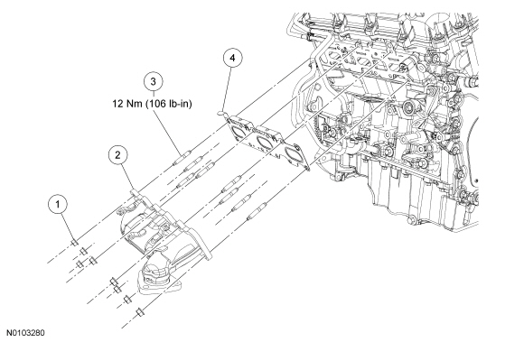
- Remove the 8 nuts and the RH exhaust manifold.
- Discard the nuts and exhaust manifold gasket.
- Clean and inspect the RH exhaust manifold. For additional information, refer to Section 303-00.
- Remove and discard the 8 RH exhaust manifold studs.
- NOTICE: Do not use metal scrapers, wire brushes, power
abrasive discs or other abrasive means to clean the sealing surfaces. These
may cause scratches and gouges resulting in leak paths. Use a plastic
scraper to clean the sealing surfaces.
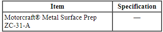
Clean the exhaust manifold mating surface of the cylinder head with metal surface prep. Follow the directions on the packaging.
Installation
- Install 8 new RH exhaust manifold studs.
- Tighten to 12 Nm (106 lb-in).
- NOTICE: Failure to tighten the exhaust manifold nuts to
specification a second time will cause the exhaust manifold to develop an
exhaust leak.
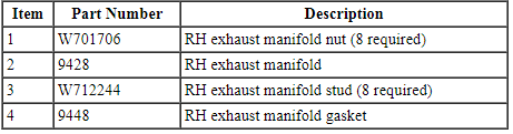
Install a new gasket, RH exhaust manifold and 8 new nuts. Tighten in 2 stages in the sequence shown:
- Stage 1: Tighten to 15 Nm (133 lb-in).
- Stage 2: Tighten to 20 Nm (177 lb-in).
- Install the RH turbocharger. For additional information, refer to Section 303-04D.
Engine Mount
Removal and Installation
- Drain the cooling system. For additional information, refer to Section 303-03.
- If equipped, remove the 4 retainers and the underbody shield.

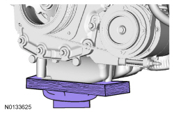
- NOTICE: Failure to position the wood block and floor jack as
illustrated can result in damage to the oil pan.
NOTE: If the vehicle is equipped with a skid plate, verify the piece of wood is clear of the skid plate.
Position a floor jack with a block of wood under the front of the oil pan.
- If equipped, remove the noise generator. For additional information, refer to Intake Air System Components - Exploded View in Section 303-12.
- Remove the engine coolant degas bottle. For additional information, refer to Section 303-03.
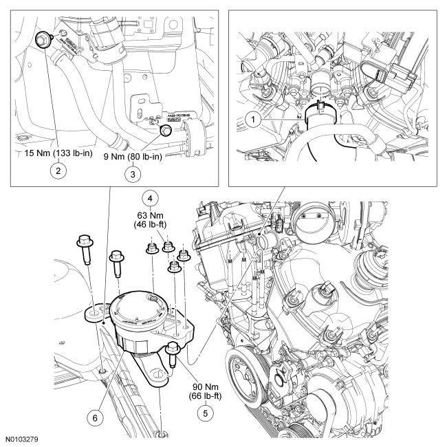
- Disconnect the upper radiator hose from the intake manifold.
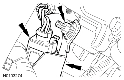
- Remove the A/C tube bracket bolt from the upper RH shock tower.
- To install, tighten to 15 Nm (133 lb-in).
- Remove the A/C tube retaining clamp bolt from the lower RH shock tower.
- To install, tighten to 9 Nm (80 lb-in).
- Remove the 4 engine mount nuts.
- To install, tighten to 63 Nm (46 lb-ft).
- Remove the 3 bolts and the engine mount.
- To install, tighten to 90 Nm (66 lb-ft).
- To install, reverse the removal procedure.
- Fill and bleed the cooling system. For additional information, refer to Section 303-03.
Oil Pan
Material
Removal
NOTICE: During engine repair procedures, cleanliness is extremely important. Any foreign material, including any material created while cleaning gasket surfaces, that enters the oil passages, coolant passages or the oil pan, may cause engine failure.
- With the vehicle in NEUTRAL, position it on a hoist. For additional information, refer to Section 100-02.
- Remove the Air Cleaner (ACL) outlet pipe. For additional information, refer to Section 303-12.
- Remove the battery tray. For additional information, refer to Section 414-01.
- Remove the oil level indicator.
- Detach the wiring harness retainer from the starter stud bolt.
- Remove the starter stud bolt.
- Loosen the 3 upper bellhousing-to-engine bolts 5 mm (0.19 in).
- Remove the RH and LH catalytic converters. For additional information, refer to Section 309-00.
- Remove the 2 engine roll restrictors. For additional information, refer to Section 307-01A.
- Remove the drain plug and drain the engine oil.
- Install the drain plug and tighten to 27 Nm (20 lb-ft).

- Remove and discard the engine oil filter.
- Remove the intermediate shaft assembly. For additional information, refer to Section 205-04.
- Remove the 3 bolts and the RH turbocharger bracket.
- Remove the 3 Power Transfer Unit (PTU) support bracket bolts and the PTU support bracket.

- Detach the wiring harness retainer from the A/C compressor stud.

- Remove the A/C compressor nut.
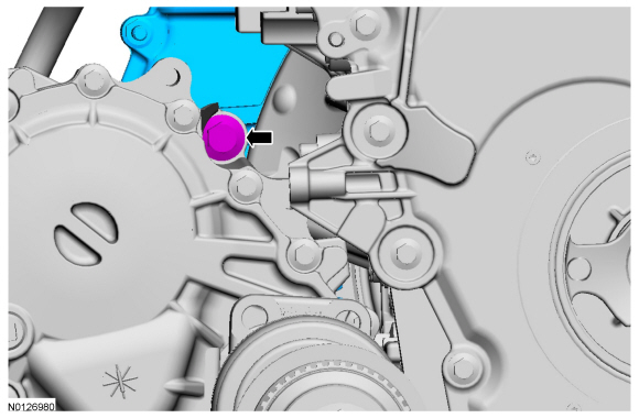
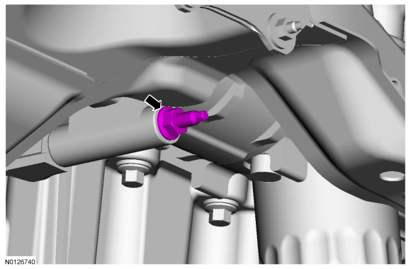
- Remove the stud from the oil pan boss (stud will remain in compressor housing).

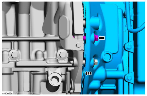
- Remove the 2 bolts and the LH turbocharger oil return tube.
- Discard the gasket and the 2 O-ring seals.

- Loosen the 3 LH bellhousing-to-engine bolts 5 mm (0.19 in).
- Loosen the RH engine-to-bellhousing bolt 5 mm (0.19 in).

- Remove the 2 fasteners and the inspection cover.

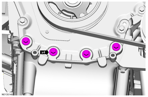
- Remove the 4 oil pan-to-bellhousing bolts.
- Separate the engine and transaxle 5 mm (0.19 in).
- Remove the 4 lower engine front cover bolts.

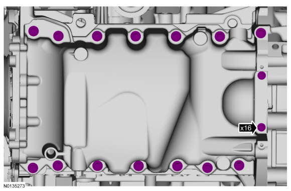
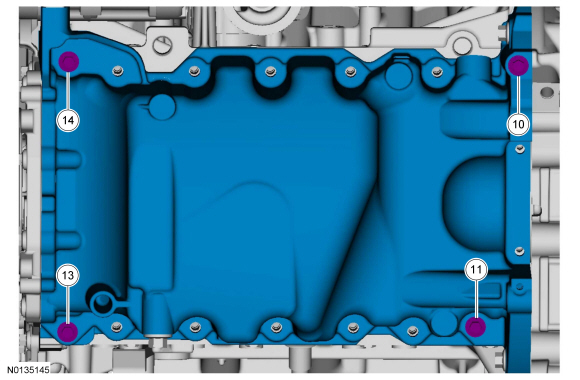
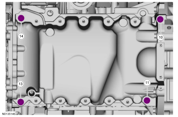
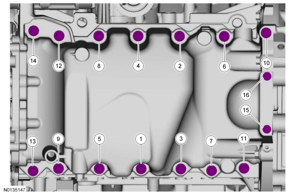
- Remove the 16 oil pan bolts.
- Using a suitable pry tool, locate the pry pads and pry the oil pan loose and remove.
- NOTICE: Only use a 3M Roloc Bristle Disk (2-in white, part
number 07528) to clean the oil pan. Do not use metal scrapers, wire brushes
or any other power abrasive disk to clean. These tools cause scratches and
gouges that make leak paths.
Clean the engine oil pan using a 3M Roloc Bristle Disk (2-in white, part number 07528) in a suitable tool turning at the recommended speed of 15,000 rpm.
- Thoroughly wash the oil pan to remove any foreign material, including any abrasive particles created during the cleaning process.
- NOTICE: Do not use wire brushes, power abrasive discs or 3M
Roloc Bristle Disk (2-in white, part number 07528) to clean the sealing
surfaces. These tools cause scratches and gouges that make leak paths. They
also cause contamination that causes premature engine failure. Remove all
traces of the gasket.
Clean the sealing surfaces of the cylinder block and engine front cover in the following sequence.
- Remove any large deposits of silicone or gasket material.
- Apply silicone gasket remover and allow to set for several minutes.
- Remove the silicone gasket remover. A second application of silicone gasket remover may be required if residual traces of silicone or gasket material remain.
- Apply metal surface prep to remove any remaining traces of oil and to prepare the surfaces to bond. Do not attempt to make the metal shiny. Some staining of the metal surfaces is normal.
Installation
- Apply a 5.5 mm (0.21 in) bead of Motorcraft High Performance Engine RTV Silicone to the 2 engine front cover-to-cylinder block joint areas on the sealing surface of the oil pan.
- NOTICE: Failure to use Motorcraft High Performance Engine RTV
Silicone may cause the engine oil to foam excessively and result in serious
engine damage.
NOTE: The oil pan and the 4 specified bolts must be installed and the oil pan aligned to the cylinder block within 4 minutes of sealant application. Final tightening of the oil pan bolts must be carried out within 60 minutes of sealant application.
Apply a 3 mm (0.11 in) bead of Motorcraft High Performance Engine RTV Silicone to the sealing surface of the oil pan-to-engine block and to the oil pan-to-engine front cover mating surface.
- Apply a 5.5 mm (0.21 in) bead of Motorcraft High Performance Engine RTV Silicone to the 2 crankshaft seal retainer plate-to-cylinder block joint areas on the sealing surface of the oil pan.
- NOTE: The oil pan and the 4 specified bolts must be installed
within 4 minutes of the start of sealant application.
NOTE: Keep the oil pan as close as possible to the transmission while installing, then slide forward towards the engine front cover to prevent wiping off of the sealant.
Install the oil pan and bolts 10, 11, 13 and 14 finger tight.
- Draw the bellhousing up to the engine by tightening the LH
bellhousing-to-engine bolt.
- Do not torque at this time.
- Draw the bellhousing up to the engine by tightening the RH
engine-to-bellhousing bolt.
- Do not torque at this time.
- Install the 4 oil pan-to-bellhousing bolts.
- Do not torque at this time.

- Install the A/C compressor stud and nut.
- Tighten the stud to 9 Nm (80 lb-in).
- Hand tighten the nut.
- Tighten bolts 10, 11, 13 and 14 in the sequence shown to 3 Nm (27 lb-in).
- Install the 4 lower engine front cover bolts.
- Do not torque at this time.

- Install the remaining oil pan bolts and tighten in the sequence shown.
- Tighten bolts 1 through 9 and 11 through 14 to 20 Nm (177 lb-in), then rotate an additional 45 degrees.
- Tighten bolts 15 and 16 to 10 Nm (89 lb-in), then rotate an additional 45 degrees.
- Tighten bolt 10 to 20 Nm (177 lb-in), then rotate an additional 90 degrees.
- Tighten the 4 lower engine front cover bolts to 24 Nm (18 lb-ft).
- Tighten the A/C compressor nut to 25 Nm (18 lb-ft).
- Attach the wiring harness retainer to the A/C compressor stud.
- Tighten the 4 oil pan-to-bellhousing bolts to 48 Nm (35 lb-ft).

- Tighten the RH engine-to-bellhousing bolt to 48 Nm (35 lb-ft).
- Tighten the 3 LH bellhousing-to-engine bolts to 48 Nm (35 lb-ft).
- Install the inspection cover and the 2 fasteners.
- Install the Power Transfer Unit (PTU) support bracket and the 3 bolts.
- Tighten to 70 Nm (52 lb-ft).
- NOTE: Lubricate the oil pan bore with clean engine oil.
Using new O-ring seals and gasket, install the LH turbocharger oil return tube and the 2 bolts.
- Tighten to 10 Nm (89 lb-in).
- Tighten the 3 upper bellhousing-to-engine bolts to 48 Nm (35 lb-ft).

- Install the RH turbocharger bracket and the 3 bolts.
- Tighten the bolt to 19 Nm (168 lb-in).
- Tighten the 2 bolts to 48 Nm (35 lb-ft).

- Install the intermediate shaft assembly. For additional information, refer to Section 205-04.
- NOTE: Do not lubricate the engine oil filter gasket.
Install a new engine oil filter.
- Tighten to 5 Nm (44 lb-in) and then rotate an additional 180 degrees.
- Install the 2 engine roll restrictors. For additional information, refer to Section 307-01A.
- Install the RH and LH catalytic converters. For additional information, refer to Section 309-00.
- Install the starter stud bolt.
- Tighten to 27 Nm (20 lb-in).
- Attach the wiring harness retainer to the starter stud bolt.

- Install the oil level indicator.
- Install the battery tray. For additional information, refer to Section 414-01.
- Install the Air Cleaner (ACL) outlet pipe. For additional information, refer to Section 303-12.
- NOTICE: Do not expose the Motorcraft High Performance Engine
RTV Silicone to engine oil for at least 90 minutes after installing the oil
pan. Failure to follow these instructions may cause engine oil leakage.
Fill the engine with clean engine oil.
Oil Pump
Special Tool(s)
Removal
NOTICE: During engine repair procedures, cleanliness is extremely important. Any foreign material, including any material created while cleaning gasket surfaces, that enters the oil passages, coolant passages or the oil pan may cause engine failure.
- Remove the engine front cover. For additional information, refer to Engine Front Cover in this section.
- Rotate the crankshaft clockwise and align the timing marks on the Variable Camshaft Timing (VCT) assemblies as shown.

- NOTE: The Camshaft Holding Tool will hold the camshafts in the
Top Dead Center (TDC) position.
Install the Camshaft Holding Tool onto the flats of the LH camshafts.

- NOTE: The Camshaft Holding Tool will hold the camshafts in
the TDC position.
Install the Camshaft Holding Tool onto the flats of the RH camshafts.
- Remove the 3 bolts and the RH VCT housing.
- Remove the 3 bolts and the LH VCT housing.

NOTE: The following 3 steps are for primary timing chains when the colored links are not visible.
- Mark the timing chain link that aligns with the timing mark on the RH intake VCT assembly as shown.
- Mark the timing chain link that aligns with the timing mark on the LH intake VCT assembly as shown.

- NOTE: The crankshaft sprocket timing mark should be between the 2
colored links.
Mark the 2 timing chain links that align with the timing mark on the crankshaft sprocket as shown.
- Remove the 2 bolts and the primary timing chain tensioner.
- Remove the primary timing chain tensioner arm.

- Remove the 2 bolts and the lower LH primary timing chain guide.
- Remove the primary timing chain.
- Remove the crankshaft timing chain sprocket.

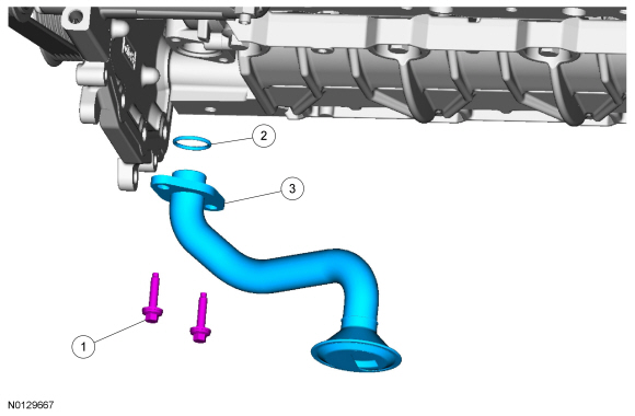
- Remove the 2 bolts and the oil pump screen and pickup tube.
- Discard the O-ring seal.

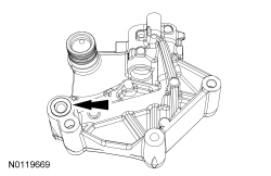
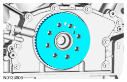
- Remove the 3 bolts and the oil pump.

Installation
- Install the oil pump and the 3 bolts.
- Tighten to 10 Nm (89 lb-in).
- Using a new O-ring seal, install the oil pump screen and pickup tube and
the 2 bolts.
- Tighten to 10 Nm (89 lb-in).
- Install the crankshaft timing chain sprocket.

- NOTE: The crankshaft sprocket timing mark should be between the 2
colored links.
Install the primary timing chain with the colored links aligned with the timing marks on the VCT assemblies and the crankshaft sprocket.
- Install the lower LH primary timing chain guide and the 2 bolts.
- Tighten to 10 Nm (89 lb-in).

- Install the primary timing chain tensioner arm.

- Reset the primary timing chain tensioner.
- Release the ratchet detent.
- Using a soft-jawed vise, compress the ratchet plunger.
- Align the hole in the ratchet plunger with the hole in the tensioner housing and install a suitable lockpin.
- NOTE: It may be necessary to rotate the crankshaft slightly to
remove slack from the timing chain and install the tensioner.
Install the primary tensioner and the 2 bolts.
- Tighten to 10 Nm (89 lb-in).
- Remove the lockpin.

- As a post-check, verify correct alignment of all timing marks.
- There are 48 links between the RH intake VCT assembly colored link (1) and the LH intake VCT assembly colored link (2).
- There are 35 links between the LH intake VCT assembly colored link (2) and the 2 crankshaft sprockets colored links (3).
- Inspect the VCT housing seals for damage and replace as necessary.

- NOTE: RH shown, LH similar.
NOTE: During removal, the O-ring seal may remain on the cylinder head. If so, remove the O-ring seal from the cylinder head, inspect the seal (replace as necessary) and install the O-ring seal on the VCT housing.
Inspect the VCT housing-to-cylinder head O-ring seals for damage and replace as necessary.
- NOTICE: Make sure the dowels on the Variable Camshaft Timing
(VCT) housing are fully engaged in the cylinder head prior to tightening the
bolts. Failure to follow this process will result in severe engine damage.
Install the LH VCT housing and the 3 bolts.
- Tighten in the sequence shown to 10 Nm (89 lb-in).

- NOTICE: Make sure the dowels on the Variable Camshaft Timing
(VCT) housing are fully engaged in the cylinder head prior to tightening the
bolts. Failure to follow this process will result in severe engine damage.
Install the RH VCT housing and the 3 bolts.
- Tighten in the sequence shown to 10 Nm (89 lb-in).

- Install the engine front cover. For additional information, refer to Engine Front Cover in this section.
Oil Pump Screen and Pickup Tube
Removal
NOTICE: During engine repair procedures, cleanliness is extremely important. Any foreign material, including any material created while cleaning gasket surfaces, that enters the oil passages, coolant passages or the oil pan may cause engine failure.
- Remove the oil pan. For additional information, refer to Oil Pan in this section.
- Remove the 2 bolts and the oil pump screen and pickup tube.
- Discard the O-ring seal.
Installation
- Using a new O-ring seal, install the oil pump screen and pickup tube and
the 2 bolts.
- Tighten to 10 Nm (89 lb-in).
- Install the oil pan. For additional information, refer to Oil Pan in this section.
Crankshaft Rear Seal with Retainer Plate
Material
Removal
NOTICE: During engine repair procedures, cleanliness is extremely important. Any foreign material, including any material created while cleaning gasket surfaces that enters the oil passages, coolant passages or the oil pan, may cause engine failure.
- With the vehicle in NEUTRAL, position it on a hoist. For additional information, refer to Section 100-02.
- Remove the flexplate. For additional information, refer to Flexplate in this section.
- Remove the crankshaft sensor ring.
- Disconnect the Crankshaft Position (CKP) sensor electrical connector.
- Remove the bolt and the CKP sensor.
- Remove the 2 oil pan to crankshaft rear seal retainer bolts.

- Remove the 8 bolts and the crankshaft rear seal retainer plate.
- Discard the plate and seal assembly.
- NOTICE: Place clean, lint-free shop towels over exposed engine
cavities. Carefully remove the towels so foreign material is not dropped
into the engine. Any foreign material (including any material created while
cleaning gasket surfaces) that enters the oil passages or the oil pan, may
cause engine failure.
NOTICE: Do not use wire brushes, power abrasive discs or 3M Roloc Bristle Disk (2-in white, part number 07528) to clean the sealing surfaces. These tools cause scratches and gouges that make leak paths. They also cause contamination that will cause premature engine failure. Remove all traces of the gasket.
Clean the sealing surfaces of the cylinder block and oil pan flange in the following sequence.- Remove any large deposits of silicone or gasket material.
- Apply silicone gasket remover and allow to set for several minutes.
- Remove the silicone gasket remover. A second application of silicone gasket remover may be required if residual traces of silicone or gasket material remain.
- Apply metal surface prep to remove any remaining traces of oil or coolant and to prepare the surfaces to bond. Do not attempt to make the metal shiny. Some staining of the metal surfaces is normal.
Installation
- NOTICE: Failure to use Motorcraft High Performance Engine RTV
Silicone may cause the engine oil to foam excessively and result in serious
engine damage.
NOTE: The crankshaft rear seal retainer must be installed and the bolts tightened within 10 minutes of sealant application.
Apply 5 mm (0.196 in) beads of Motorcraft High Performance Engine RTV Silicone to the 2 cylinder block/oil pan joints.
- NOTICE: Failure to use Motorcraft High Performance Engine RTV
Silicone may cause the engine oil to foam excessively and result in serious
engine damage.
NOTE: The crankshaft rear seal retainer must be installed and the bolts tightened within 10 minutes of sealant application.
Apply a 3 mm (0.11 in) bead of Motorcraft High Performance Engine RTV Silicone to the sealing surface of the crankshaft rear seal retainer plate.
- NOTE: Use the 2 oil pan bolts as handles during installation to
avoid touching the sealant.
NOTE: Lubricate the crankshaft rear seal with clean engine oil.
Install the crankshaft rear seal retainer at an angle above the oil pan flange to avoid scraping off the sealer. Tilt the seal retainer up and onto the rear of the cylinder block.
- Install the 8 bolts and tighten in the sequence shown to 10 Nm (89 lb-in).
- Install the 2 oil pan to crankshaft rear seal retainer bolts.
- Tighten to 10 Nm (89 lb-in) plus an additional 45 degrees.
- Install the Crankshaft Position (CKP) sensor and install the bolt.
- Tighten to 10 Nm (89 lb-in).

- Connect the CKP sensor electrical connector.

- Install the crankshaft sensor ring.

- Install the flexplate. For additional information, refer to Flexplate in this section.
 Specifications, Description and Operation, General Procedures
SPECIFICATIONS
Material
General Specifications
Torque Specifications
a Tighten to 10 Nm (89 lb-in) plus an additional 720 degrees.
b Tighten to 16 Nm (142 lb-in) plus an addition ...
 Removal
Engine
Special Tool(s)
WARNING: Do not smoke, carry lighted tobacco or have an open flame of any
type when working on or near any fuel-related component. Highly flammable
mixtures are always ...
Other materials:
Assembly
Engine
Special Tool(s)
Material
Engine - External Components
Engine - Front and Upper Components
Engine - Lower Block Components
NOTICE: Do not loosen or remove the crankshaft pulley bolt without
first installing the special tools as instructed in this procedure. The
crankshaft pu ...
Child Safety
• You are required by law to properly use safety seats for infants and
toddlers in the United States and Canada.
• Many states and provinces require that small children use approved
booster seats until they reach age eight, a height of 4 feet 9 inches
(1.45 meters) tall, or 80 pounds (36 ...
Diagnosis and Testing
Roof Opening Panel
Special Tool(s)
Principles of Operation
Roof Opening Panel
The roof opening panel assembly uses an integrated motor and module to
operate the roof opening panel. The roof opening panel motor and module are
installed new as an assembly. The roof opening panel is an electronicall ...
