Climate Control System
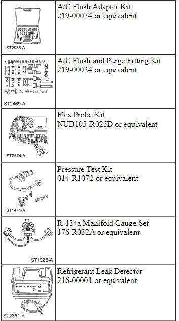
Special Tool(s)
Principles of Operation
For additional refrigerant system and component information, refer to Section 412-01.
Climate Control System Network Communication
The controls for the climate control system are in one or more locations depending on vehicle option content:
- FCIM
- IPC (if equipped with steering wheel controls
- FDIM (attached to the APIM )
When the FDIM touchscreen or voice commands are used, the APIM sends a function request message over the I-CAN to the FCIM.
When the IPC steering wheel controls are used, the IPC sends a function request message over the I-CAN to the FCIM.
The FCIM receives the climate control selections from pressing the buttons on its own controls (interface), the APIM or IPC and sends the requests to the HVAC module in the following message path:
- The FCIM sends the requests over the I-CAN to the IPC.
- The IPC relays the requests to the BCM over the HS-CAN.
- The BCM sends the requests to the HVAC module over the MS-CAN.
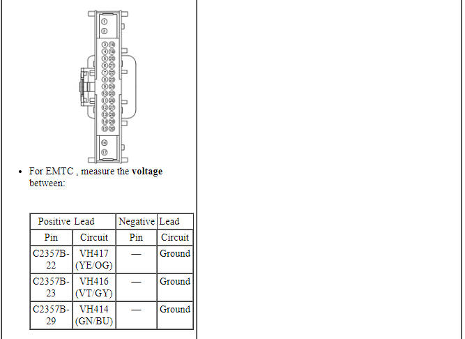
For EMTC systems, the messaging path is followed in reverse for any status updates that need to be sent from the HVAC module to the FCIM, then if applicable, to the IPC or FCDIM (through the APIM ).
For DATC systems, the messaging path is followed in reverse for any status updates that need to be sent from the HVAC module to the FCIM, FCDIM (non-touchscreen), FDIM (through the APIM ) and IPC message center.
Climate Control System Logic
Blower Motor Speed
When blower speed is selected, the FCIM sends the desired blower speed to the HVAC module using the message path described above. The HVAC module then commands the blower motor speed control to the desired speed. The HVAC module monitors the blower motor speed control feedback circuit to make sure the blower motor is at the desired speed.
Airflow Mode Selection
When an airflow mode is selected, the FCIM determines the applicable and allowable airflow direction. The FCIM then sends this desired airflow direction to the HVAC module using the message path described above. The HVAC module determines the actuator position required to deliver the correct airflow direction. While monitoring the defrost/panel/floor feedback circuit, the HVAC module drives the actuator until the feedback circuit indicates the actuator has reached its required position.
Temperature Selection
When a temperature is selected, the FCIM sends the desired temperature selection to the HVAC module using the message path described above. The HVAC module then determines the temperature blend door desired position. While monitoring the temperature blend door feedback circuit, the HVAC module drives the actuator until the feedback circuit indicates the actuator has reached its desired position.
Air Inlet Selection
When fresh air or RECIRC mode is selected, the FCIM sends the desired selection to the HVAC module using the message path described above. The HVAC module drives the air inlet mode door actuator until the HVAC module detects the actuator reached its end of travel. A spike in current draw tells the HVAC module the actuator has reached the end of its travel.
A/C Selection
When A/C is selected, the FCIM sends the selection to the HVAC module using the message path described above. If the ambient air temperature is sufficient, the HVAC module then sends the request to the BCM over the MS-CAN. The BCM then sends the request to the PCM over the HS-CAN.
FET Protection
A FET is a type of transistor that, when used with module software, monitors and controls current flow on module outputs. The FET protection strategy prevents module damage in the event of excessive current flow.
The HVAC module utilizes a FET protective circuit strategy for its actuator outputs. Output load (current level) is monitored for excessive current (typically short circuits) and shuts down (turns off the voltage or ground provided by the module) when a fault event is detected. A short circuit DTC is stored at the fault event and a cumulative counter is started.
When the demand for the output is no longer present, the module resets the FET circuit protection to allow the circuit to function. The next time the driver requests a circuit to activate that has been shut down by a previous short ( FET protection) and the circuit is still shorted, the FET protection shuts off the circuit again and the cumulative counter advances. If excessive circuit load occurs repeatedly, the module shuts down the output until a repair procedure is carried out.
When each tolerance level is reached, DTC U1000:00 should set (U1000:00 may or may not set) along with the short circuit DTC that was stored on the first failure. These DTCs cannot be cleared by a command to clear the DTCs. The module does not allow the DTC to be cleared or the circuit to be restored to normal operation until a successful self-test proves the fault has been repaired. After the self-test has successfully completed (no on-demand DTCs present), DTC U1000:00 and the associated DTC (the DTC related to the shorted circuit) automatically clears and the circuit function returns.
The module never resets the fault event counter to zero and continues to advance the fault event counter as short circuit fault events occur. If the number of short circuit fault events reach the third level, DTC U3000:49 set along with the associated short circuit DTC. DTC U3000:49 cannot be cleared and a new module must be installed after the initial fault is repaired.
CASS
Liquid refrigerant may accumulate in the A/C compressor under certain conditions. To alleviate damage to the A/C compressor, CASS is utilized.
CASS is initiated only under specific conditions:
- The ignition is off for more than 8 hours
- The ambient temperature is above -4ÂşC (25ÂşF)
- Battery voltage is above 8.5 volts during engine cranking
When these conditions are present, the PCM activates the A/C control relay prior to cranking of the engine. The A/C control relay engages the A/C compressor for approximately 4-15 A/C compressor revolutions or a maximum of 2 seconds (depending upon vehicle application), allowing the liquid refrigerant to be pushed from the A/C compressor. CASS is initiated by the PCM regardless of the HVAC system settings.
The Refrigerant Cycle
During stabilized conditions (A/C system shutdown), the refrigerant pressures are equal throughout the system. When the A/C compressor is in operation, it increases pressure on the refrigerant vapor, raising its temperature. The high-pressure and high-temperature vapor is then released into the top of the A/C condenser core.
The A/C condenser, being close to ambient temperature, causes the refrigerant vapor to condense into a liquid when heat is removed from the refrigerant by ambient air passing over the fins and tubing. The now liquid refrigerant, still at high pressure, exits from the bottom of the A/C condenser and enters the inlet side of the A/C receiver/drier. The receiver/drier is designed to remove moisture from the refrigerant.
The outlet of the receiver/drier is connected to the TXV. The TXV provides the orifice which is the restriction in the refrigerant system and separates the high and low pressure sides of the A/C system. As the liquid refrigerant passes across this restriction, its pressure and boiling point are reduced.
The liquid refrigerant is now at its lowest pressure and temperature. As it passes through the A/C evaporator, it absorbs heat from the airflow passing over the plate/fin sections of the A/C evaporator. This addition of heat causes the refrigerant to boil (convert to gas). The now cooler air can no longer support the same humidity level of the warmer air and this excess moisture condenses on the exterior of the evaporator coils and fins and drains outside the vehicle.
The refrigerant cycle is now repeated with the A/C compressor again increasing the pressure and temperature of the refrigerant.
The evaporator temperature sensor (attached to the evaporator core fins) controls A/C clutch cycling. If the temperature of the evaporator core is low enough to cause the condensed water vapor to freeze, the A/C clutch is disengaged by the vehicle PCM.
The externally controlled variable displacement compressor is electronically controlled by the PCM. The PCM pulse width modulates the solenoid in the compressor to control the compressor displacement. The PCM changes the compressor displacement based upon the:
- evaporator temperature
- ambient air temperature
- engine rpm
- vehicle speed
- A/C high side pressure
- intake air temperature
The high-side line pressure is monitored so that A/C compressor operation will be interrupted if the system pressure becomes too high or is determined to be too low (low charge condition).
The A/C compressor pressure relief valve opens and vents refrigerant to relieve unusually high system pressure.
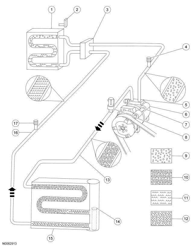
TXV Type Refrigerant System - GTDI
- A/C evaporator core
- A/C evaporator core temperature sensor
- TXV
- A/C suction line
- A/C charge valve port (low side)
- A/C compressor
- A/C pressure relief valve
- A/C pressure transducer
- Compressor discharge line
- Low pressure vapor
- High pressure vapor
- Low pressure liquid
- High pressure liquid
- A/C condenser core
- Condenser-to-receiver/drier line
- A/C receiver/drier
- A/C charge valve port (high side)
- Evaporator inlet line
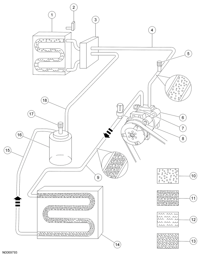
TXV Type Refrigerant System - Ti-VCT
- A/C evaporator core
- A/C evaporator core temperature sensor
- TXV
- A/C charge valve port (low side)
- A/C suction line
- A/C compressor
- A/C pressure relief valve
- A/C pressure transducer
- Low pressure vapor
- High pressure vapor
- Low pressure liquid
- High pressure liquid
- Compressor discharge line
- A/C desiccant bag
- A/C condenser core with A/C receiver/drier
- Condenser-to-evaporator line
- A/C charge valve port (high side)
Inspection and Verification
- Verify the customer concern by operating the climate control system to duplicate the condition.
- Visually inspect for obvious signs of mechanical or electrical damage.
Visual Inspection Chart
- If an obvious cause for an observed or reported concern is found, correct the cause (if possible) before proceeding to the next step.
- NOTE: Make sure to use the latest scan tool software release.
If the cause is not visually evident, connect the scan tool to the DLC.
- NOTE: The VCM LED prove-out confirms voltage and ground from
the DLC are provided to the VCM.
If the scan tool does not communicate with the VCM :
- check the VCM connection to the vehicle.
- check the scan tool connection to the VCM.
- refer to Section 418-00, No Power To The Scan Tool, to diagnose no voltage to the scan tool.
- If the scan tool does not communicate with the vehicle:
- verify the ignition key is in the ON position.
- verify the scan tool operation with a known good vehicle.
- refer to Section 418-00, The PCM Does Not Respond, to diagnose no response from the PCM.
- Carry out the network test.
- If the scan tool responds with no communication from one or more modules, refer to Section 418-00.
- If the network test passes, retrieve and record the CMDTCs.
- Clear the CMDTCs and carry out the self-test diagnostics from the PCM, HVAC module.
- NOTE: Some PCM DTCs may inhibit A/C operation. If any PCM DTCs
are retrieved, diagnose those first. Refer to the PCM DTC Chart.
If the PCM DTCs retrieved are related to the concern, go to the PCM DTC Chart in this section. If the HVAC module DTCs retrieved are related to the concern, go to the HVAC Module DTC Chart in this section. For all other DTCs, refer to Section 419-10.
- If no DTCs related to the concern are retrieved, GO to Symptom Chart - Climate Control Systems or GO to Symptom Chart - NVH.
DTC Charts
Diagnostics in this manual assume a certain skill level and knowledge of Ford-specific diagnostic practices. Refer to Diagnostic Methods in Section 100-00 for information about these practices.
PCM DTC Chart
HVAC Module DTC Chart
NOTE: This module utilizes a 5-character DTC followed by a 2-character failure-type code. The failure-type code provides information about specific fault conditions such as opens or shorts to ground. CMDTCs have an additional 2-character DTC status code suffix to assist in determining DTC history.
NOTE: Network DTCs (U-codes) are often a result of intermittent concerns such as damaged wiring or low battery voltage occurrences. Additionally, vehicle repair procedures such as module reprogramming often set network DTCs. Replacing a module to resolve a network DTC is unlikely to resolve the concern. To prevent repeat network DTC concerns, inspect all network wiring, especially connectors. Test the vehicle battery, refer to Section 414-01.

Symptom Chart - Climate Control Systems
Diagnostics in this manual assume a certain skill level and knowledge of Ford-specific diagnostic practices. Refer to Diagnostic Methods in Section 100-00 for information about these practices.
NOTE: Some PCM DTCs may inhibit A/C operation. If any PCM DTCs are retrieved, diagnose those first. Refer to the PCM DTC Chart.

Symptom Chart - NVH
NOTE: NVH symptoms will be identified using the diagnostic tools that are available. For a list of these tools, an explanation of their uses and a glossary of common terms, refer to Section 100-04. Since it is possible any one of multiple systems may be the cause of a symptom, it may be necessary to use a process of elimination type of diagnostic approach to pinpoint the responsible system. If this is not the causal system for the symptom, refer back to Section 100-04 for the next likely system and continue diagnosis.
Pinpoint Tests
Pinpoint Test A: DTC P0532 or P0533
Diagnostic Overview
Diagnostics in this manual assume a certain skill level and knowledge of Ford-specific diagnostic practices. Refer to Diagnostic Methods in Section 100-00 for information about these practices.
Refer to Wiring Diagrams Cell 54, Manual Climate Control System for schematic and connector information.
Refer to Wiring Diagrams Cell 55, Automatic Climate Control System for schematic and connector information.
Normal Operation and Fault Conditions
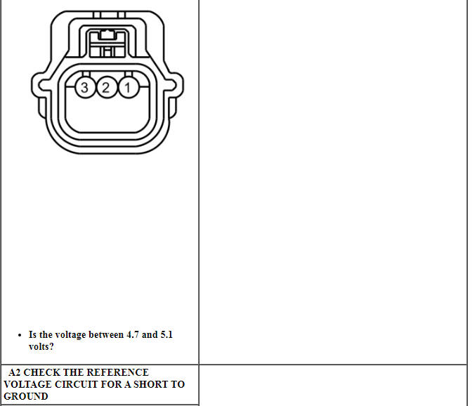
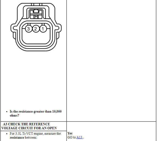
The A/C pressure transducer receives a ground from the PCM. A 5-volt reference voltage is supplied to the A/C pressure transducer from the PCM. The A/C pressure transducer then sends a voltage to the PCM to indicate the A/C refrigerant pressure.
DTC Fault Trigger Conditions
-
Possible Sources
- Wiring, terminals or connectors
- A/C pressure transducer
- PCM
-
Visual Inspection and Diagnostic Pre-checks
- Inspect loose or corroded PCM and A/C pressure transducer connections.
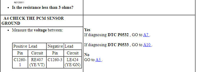
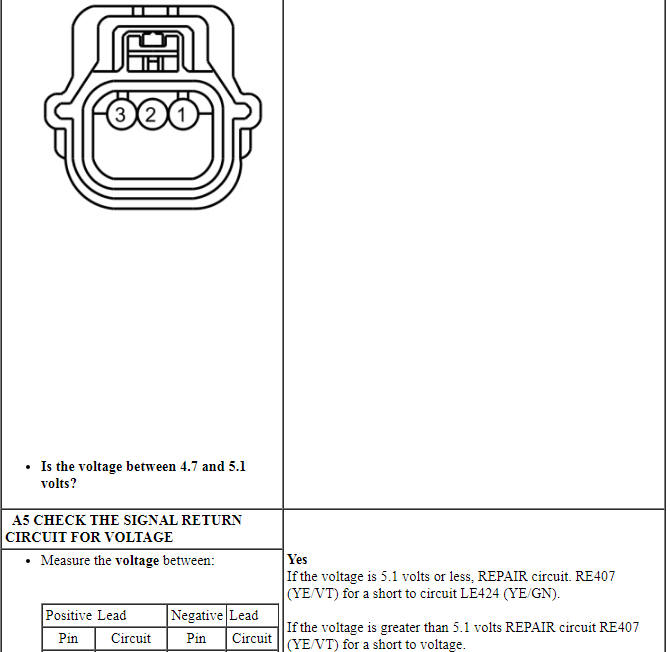
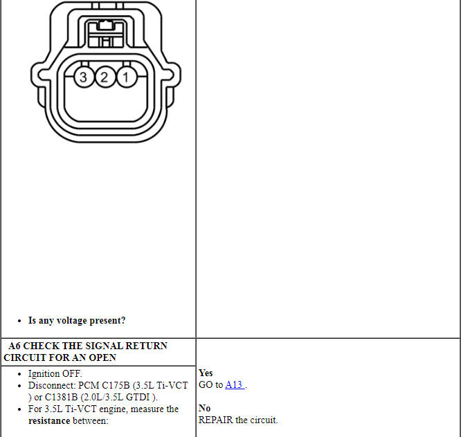
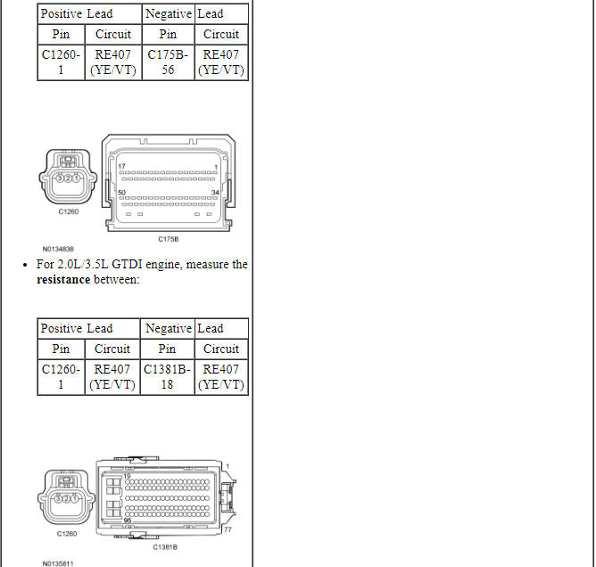
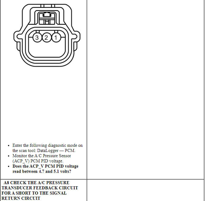
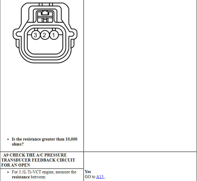
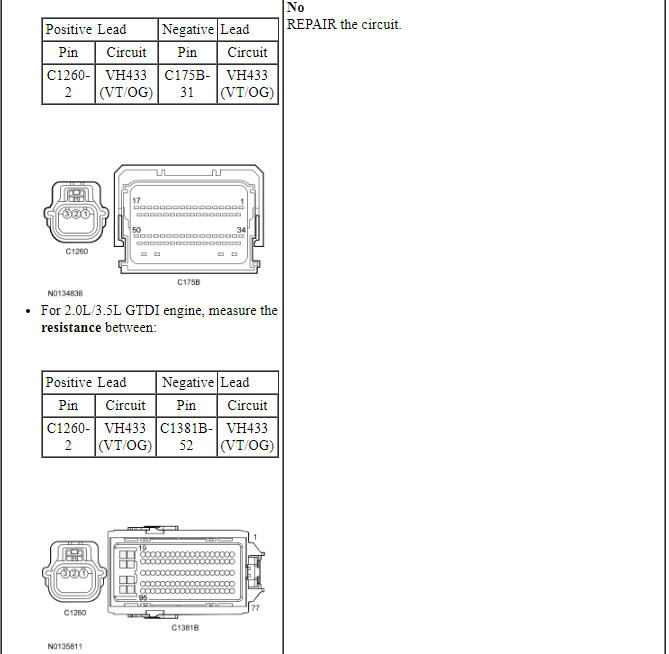
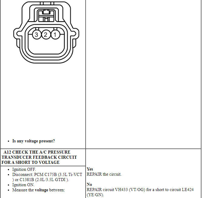
PINPOINT TEST A: DTC P0532 OR P0533

Pinpoint Test B: DTC P0645
Diagnostic Overview
Diagnostics in this manual assume a certain skill level and knowledge of Ford-specific diagnostic practices. Refer to Diagnostic Methods in Section 100-00 for information about these practices.
Refer to Wiring Diagrams Cell 54, Manual Climate Control System for schematic and connector information.
Refer to Wiring Diagrams Cell 55, Automatic Climate Control System for schematic and connector information.
Normal Operation and Fault Conditions
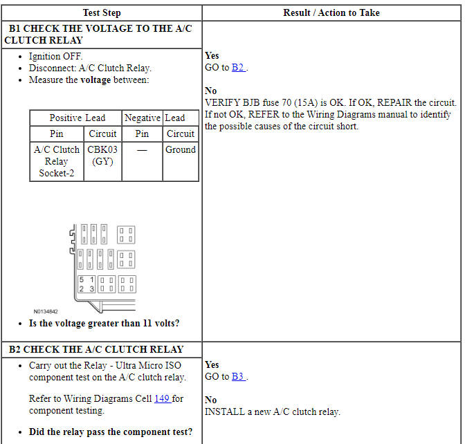
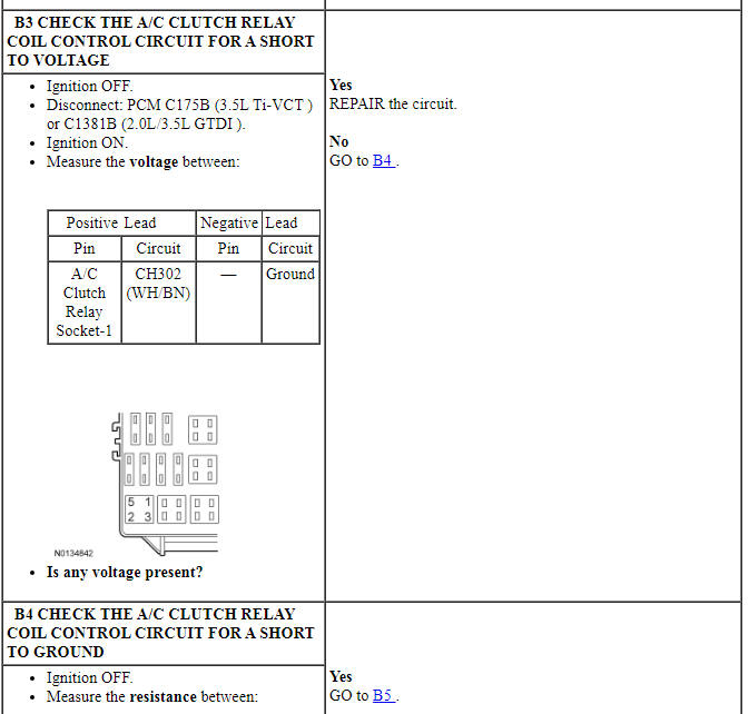
Voltage is provided to the A/C clutch relay coil. When A/C is requested and A/C line pressures allow, a ground is provided to the A/C clutch relay coil from the PCM, energizing the A/C clutch relay.
DTC Fault Trigger Conditions
-
Possible Sources
- Wiring, terminals or connectors
- A/C clutch relay
- PCM
-
Visual Inspection and Diagnostic Pre-checks
- Inspect loose or corroded PCM and A/C clutch relay connections.
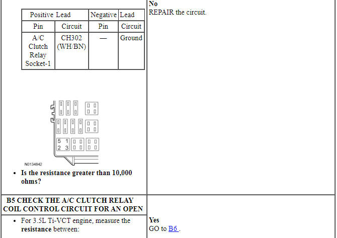
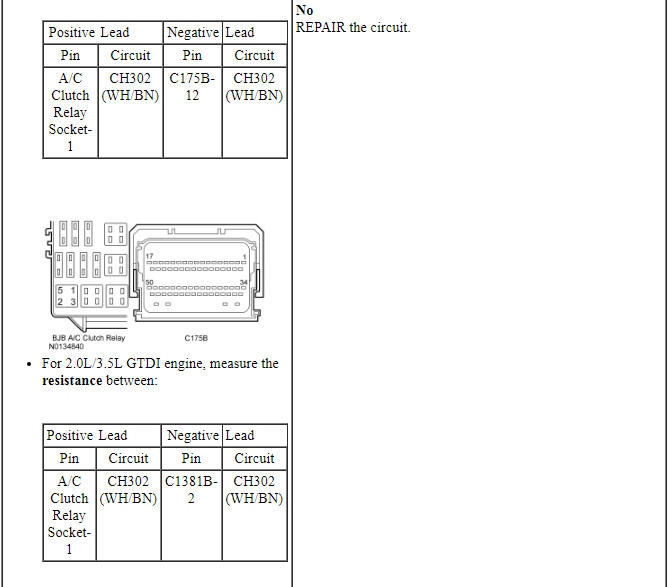
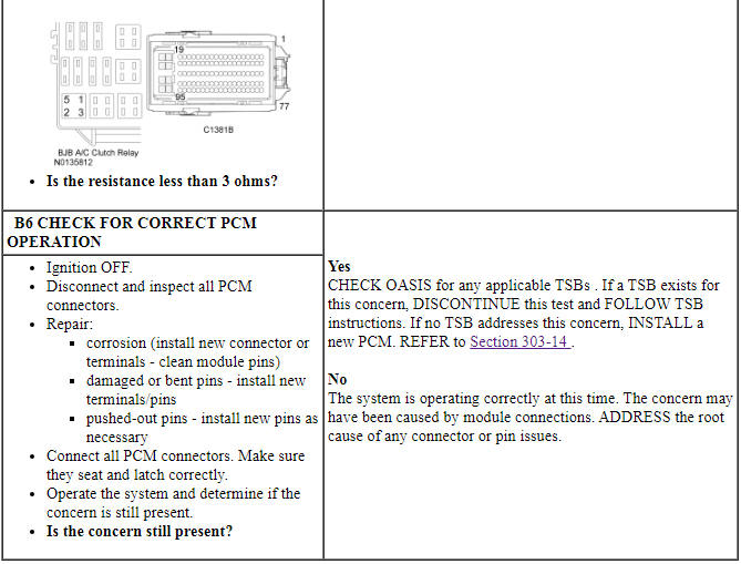
PINPOINT TEST B: DTC P0645
Pinpoint Test C: DTCs C1B14:11 or 12
Diagnostic Overview
Diagnostics in this manual assume a certain skill level and knowledge of Ford-specific diagnostic practices. Refer to Diagnostic Methods in Section 100-00 for information about these practices.
Refer to Wiring Diagrams Cell 54, Manual Climate Control System for schematic and connector information.
Refer to Wiring Diagrams Cell 55, Automatic Climate Control System for schematic and connector information.
Normal Operation and Fault Conditions
A 5-volt reference voltage is supplied to the sensors and actuators from the HVAC module.
DTC Fault Trigger Conditions
-
Possible Sources
- Wiring, terminals or connectors
- HVAC module
-
Visual Inspection and Diagnostic Pre-checks
- Inspect loose or corroded HVAC module connections.
PINPOINT TEST C: DTCs C1B14:11 OR 12
Pinpoint Test D: DTCs B1A61:11 or 15
Diagnostic Overview
Diagnostics in this manual assume a certain skill level and knowledge of Ford-specific diagnostic practices. Refer to Diagnostic Methods in Section 100-00 for information about these practices.
Refer to Wiring Diagrams Cell 54, Manual Climate Control System for schematic and connector information.
Refer to Wiring Diagrams Cell 55, Automatic Climate Control System for schematic and connector information.
Normal Operation and Fault Conditions
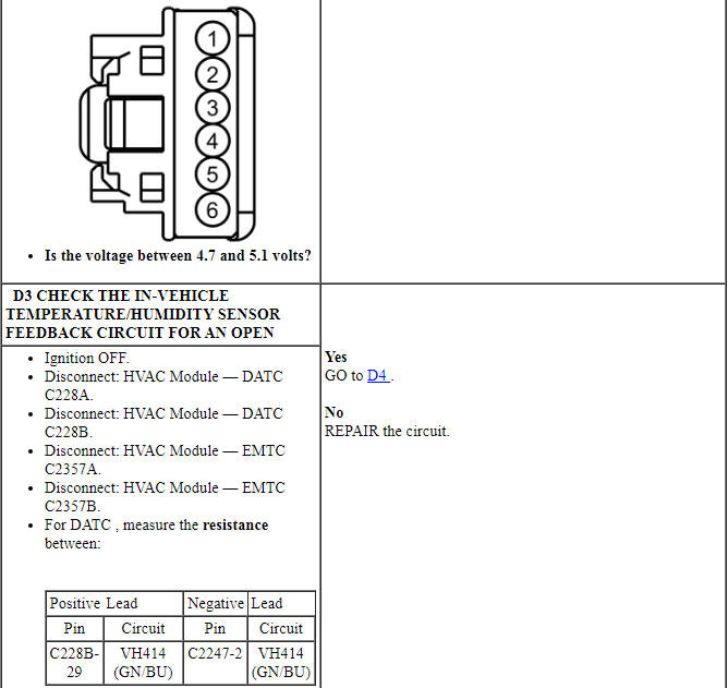
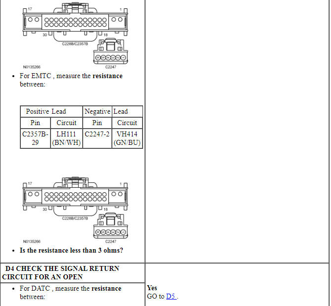
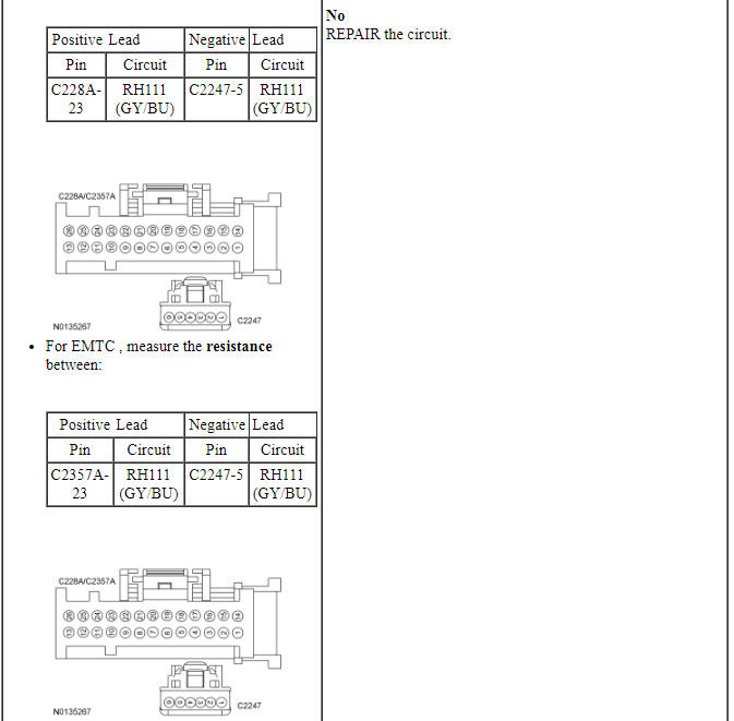
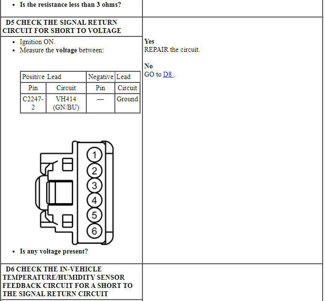
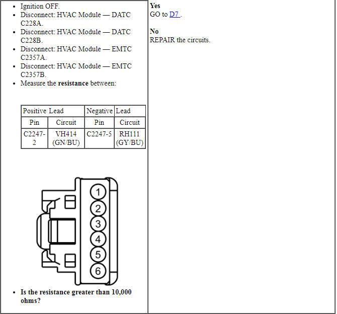
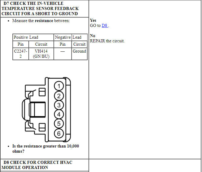
The in-vehicle temperature and humidity sensor receives a ground from the HVAC module. The sensor varies its resistance with the temperature. As the temperature rises, the resistance falls. As the temperature falls the resistance rises. The HVAC module measures this resistance to determine the temperature at the sensor. The sensor DTCs set if there is a fault in either the temperature or humidity part of the sensor or circuits.
DTC Fault Trigger Conditions

-
Possible Sources
- Wiring, terminals or connectors
- In-vehicle temperature/humidity sensor
- HVAC module
-
Visual Inspection and Diagnostic Pre-checks
- Make sure the in-vehicle temperature/humidity sensor harness is not chaffed.
PINPOINT TEST D: DTCs B1A61:11 OR 15
Pinpoint Test E: DTCs B1A63:11, B1A63:15, B1A64:11, B1A64:15
Diagnostic Overview
Diagnostics in this manual assume a certain skill level and knowledge of Ford-specific diagnostic practices. Refer to Diagnostic Methods in Section 100-00 for information about these practices.
Refer to Wiring Diagrams Cell 54, Manual Climate Control System for schematic and connector information.
Refer to Wiring Diagrams Cell 55, Automatic Climate Control System for schematic and connector information.
Normal Operation and Fault Conditions
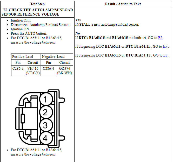
As the light applied to the sensor changes, the HVAC module detects the change through the RH and LH feedback circuits.
DTC Fault Trigger Conditions
-
Possible Sources
- Wiring, terminals or connectors
- Autolamp/sunload sensor
- HVAC module
-
Visual Inspection and Diagnostic Pre-checks
- Inspect loose or corroded HVAC module and autolamp/sunload sensor connections.
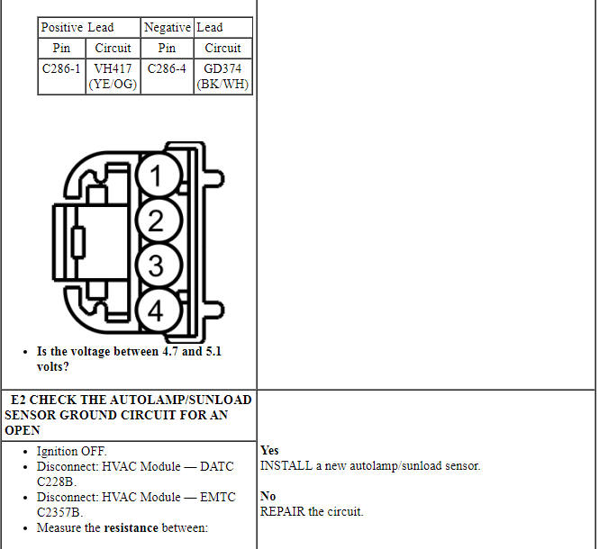
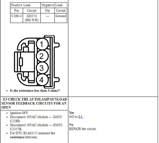
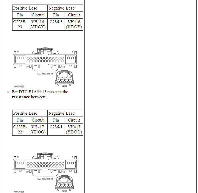
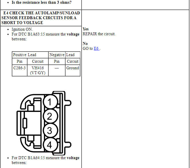
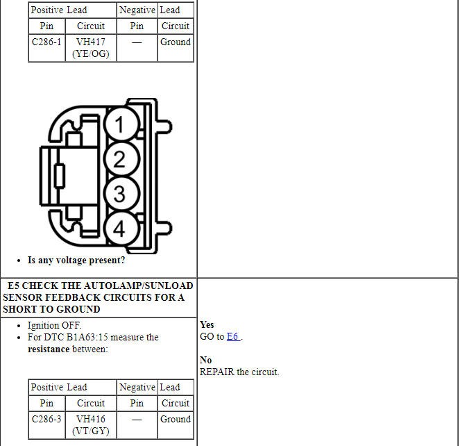
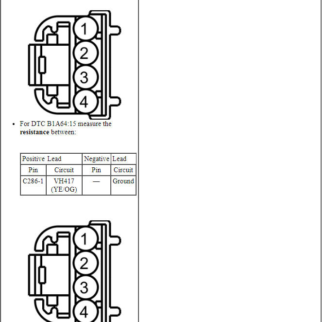
PINPOINT TEST E: DTCs B1A63:11, B1A63:15, B1A64:11, B1A64:15
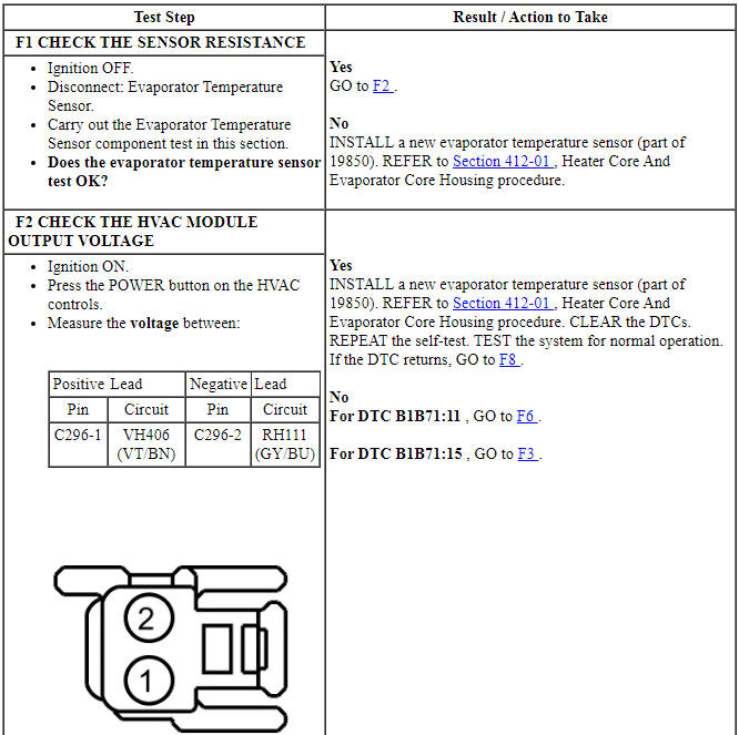
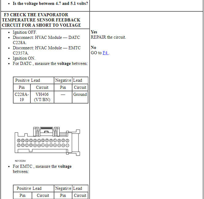
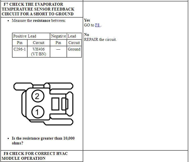
Pinpoint Test F: DTCs B1B71:11 or 15
Diagnostic Overview
Diagnostics in this manual assume a certain skill level and knowledge of Ford-specific diagnostic practices. Refer to Diagnostic Methods in Section 100-00 for information about these practices.
Refer to Wiring Diagrams Cell 54, Manual Climate Control System for schematic and connector information.
Refer to Wiring Diagrams Cell 55, Automatic Climate Control System for schematic and connector information.
Normal Operation and Fault Conditions
The evaporator temperature sensor receives a ground from the HVAC module. The sensor varies its resistance with the temperature. As the temperature rises, the resistance falls. As the temperature falls, the resistance rises. The HVAC module measures this resistance to determine the temperature at the sensor.
The evaporator temperature sensor is used for A/C compressor cycling. An accurate evaporator temperature is critical to prevent evaporator icing. The HVAC module uses the temperature measurement to turn off the A/C compressor before the evaporator temperatures are cold enough to freeze the condensation. This prevents ice blockage of airflow over the evaporator core.
DTC Fault Trigger Conditions
-
Possible Sources
- Wiring, terminals or connectors
- Evaporator temperature sensor
- HVAC module
-
Visual Inspection and Diagnostic Pre-checks
- Inspect loose or corroded HVAC module and evaporator temperature sensor connections.
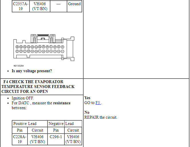
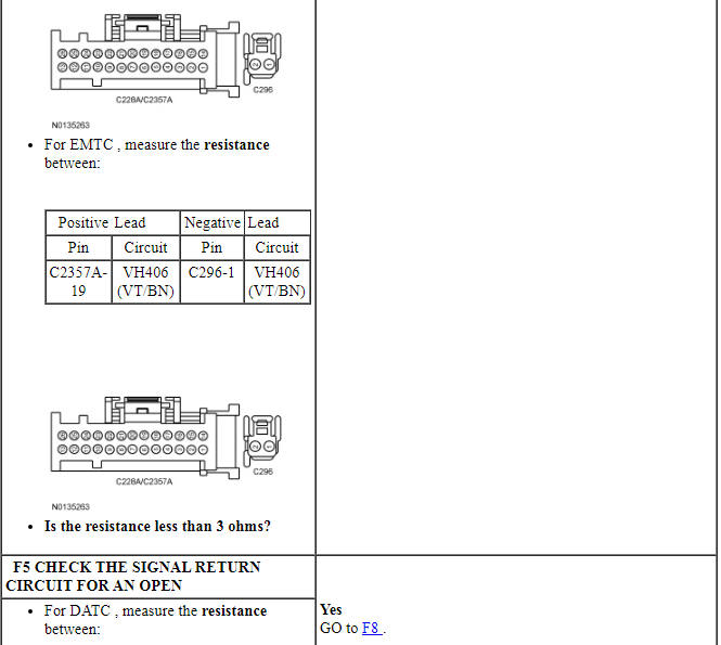
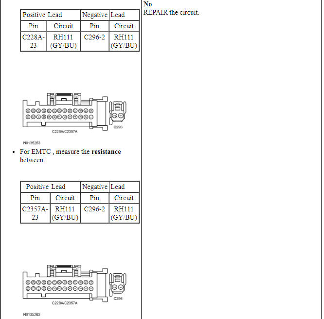
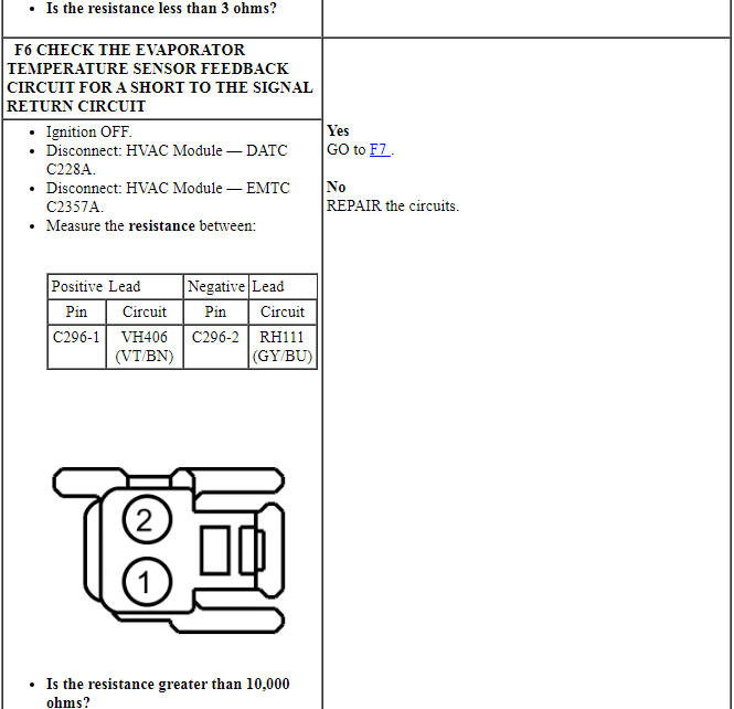
PINPOINT TEST F: DTCs B1B71:11 OR 15
Pinpoint Test G: DTCs U3003:16 or 17
Diagnostic Overview
Diagnostics in this manual assume a certain skill level and knowledge of Ford-specific diagnostic practices. Refer to Diagnostic Methods in Section 100-00 for information about these practices.
Refer to Wiring Diagrams Cell 54, Manual Climate Control System for schematic and connector information.
Refer to Wiring Diagrams Cell 55, Automatic Climate Control System for schematic and connector information.
NOTE: DTC U3003 can be set if the vehicle has been recently jump started, the battery has been recently charged or the battery has been discharged. The battery may become discharged due to excessive load(s) on the charging system from aftermarket accessories or if the battery has been left unattended with the accessories on.
NOTE: Carry out a thorough inspection and verification before proceeding with the pinpoint test. Refer to Inspection and Verification in this section.
Normal Operation and Fault Conditions
The HVAC module is supplied constant battery voltage and ground.
DTC Fault Trigger Conditions
-
Possible Sources
- Wiring, terminals or connectors
- HVAC module
-
Visual Inspection and Diagnostic Pre-checks
- Inspect loose or corroded HVAC module connections.
PINPOINT TEST G: DTCs U3003:16 OR 17

Pinpoint Test H: Unable to Duplicate the Customer Concern and No DTCs Present
Diagnostic Overview
Diagnostics in this manual assume a certain skill level and knowledge of Ford-specific diagnostic practices. Refer to Diagnostic Methods in Section 100-00 for information about these practices.
Normal Operation and Fault Conditions
This pinpoint test tests the functions of the HVAC system and identifies the correct HVAC symptom pinpoint test.
-
Possible Sources
- HVAC system and/or related components
PINPOINT TEST H: UNABLE TO DUPLICATE THE CUSTOMER CONCERN AND NO DTCs PRESENT
Pinpoint Test I: The Air Inlet Door is Inoperative
Diagnostic Overview
Diagnostics in this manual assume a certain skill level and knowledge of Ford-specific diagnostic practices. Refer to Diagnostic Methods in Section 100-00 for information about these practices.
Refer to Wiring Diagrams Cell 54, Manual Climate Control System for schematic and connector information.
Refer to Wiring Diagrams Cell 55, Automatic Climate Control System for schematic and connector information.
Normal Operation and Fault Conditions
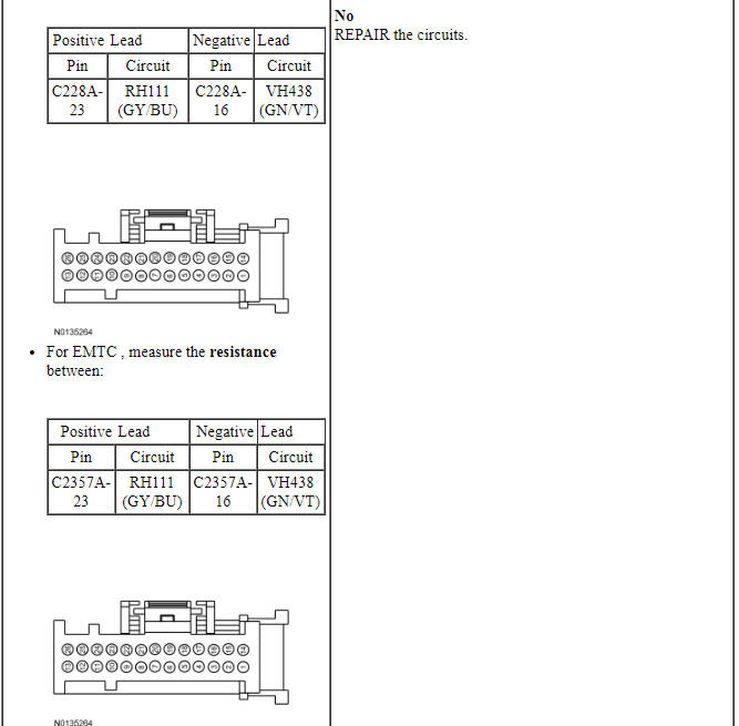
To rotate the air inlet mode door actuator, the HVAC module supplies voltage and ground to the air inlet mode door actuator through the door actuator motor circuits. To reverse the air inlet mode door actuator rotation, the HVAC module reverses the voltage and ground circuits. The air inlet mode door actuator feedback resistors are supplied a ground from the HVAC module by the air inlet mode door actuator return circuits and a 5-volt reference voltage on the air inlet mode door actuator reference circuits. The HVAC module reads the voltage on the air inlet mode door actuator feedback circuits to determine the air inlet mode door actuator position by the position of the actuator feedback resistor wiper arm.
DTC Fault Trigger Conditions
-
Possible Sources
- Wiring, terminals or connectors
- Air inlet mode door actuator
- Air inlet mode door binding or stuck
- HVAC module
- FCIM
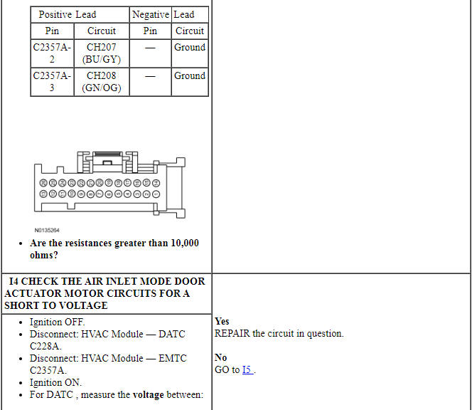
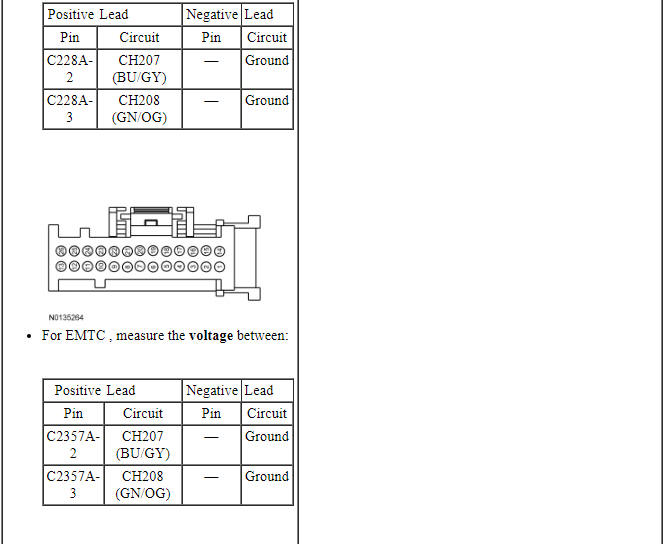
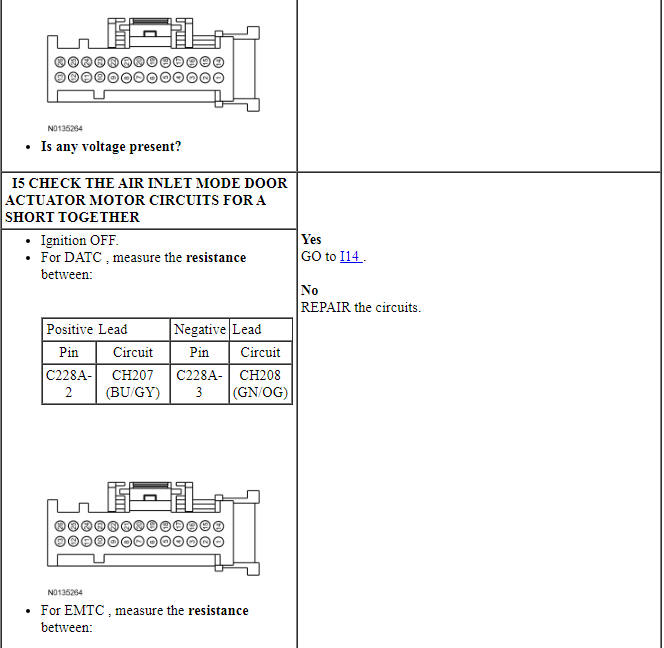
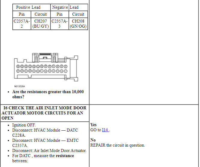
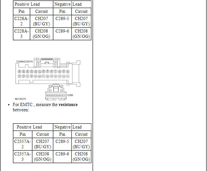
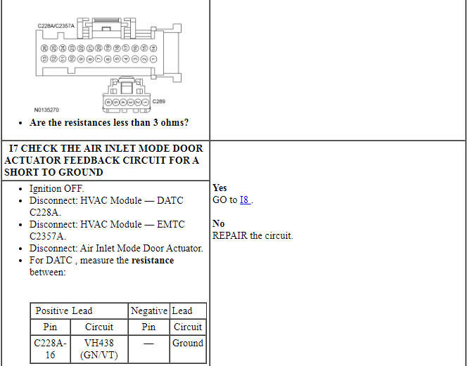
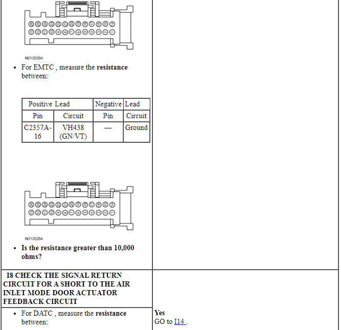
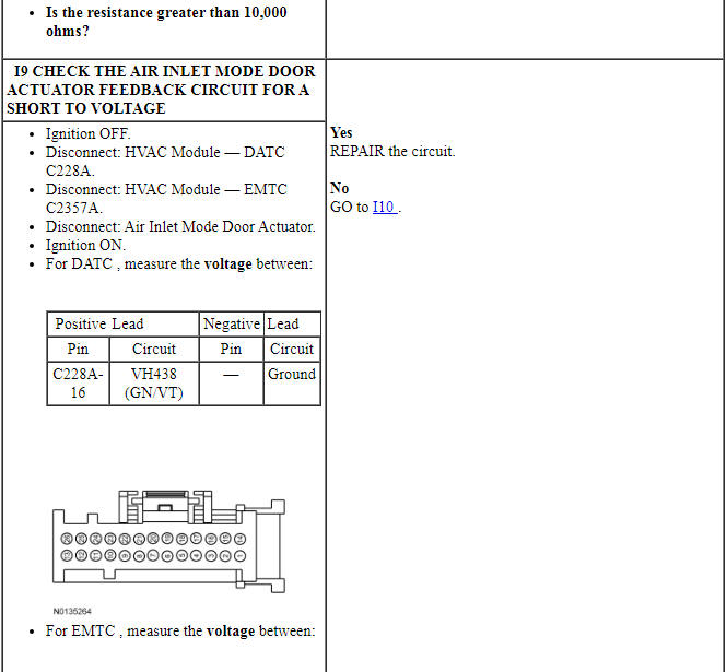
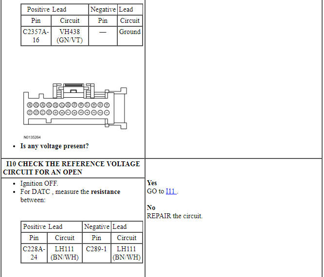
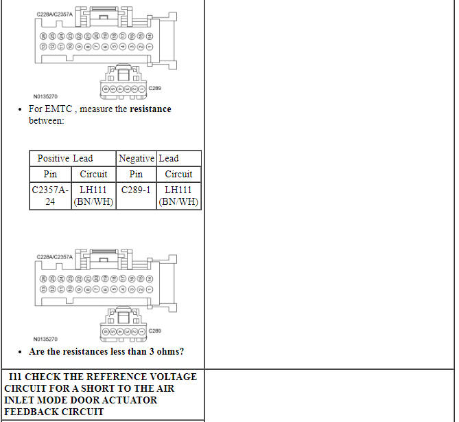
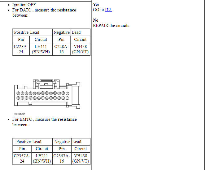
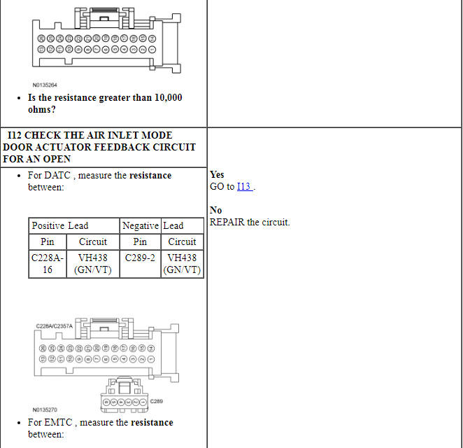
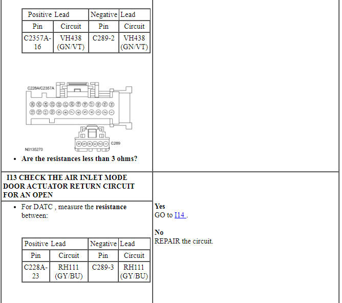
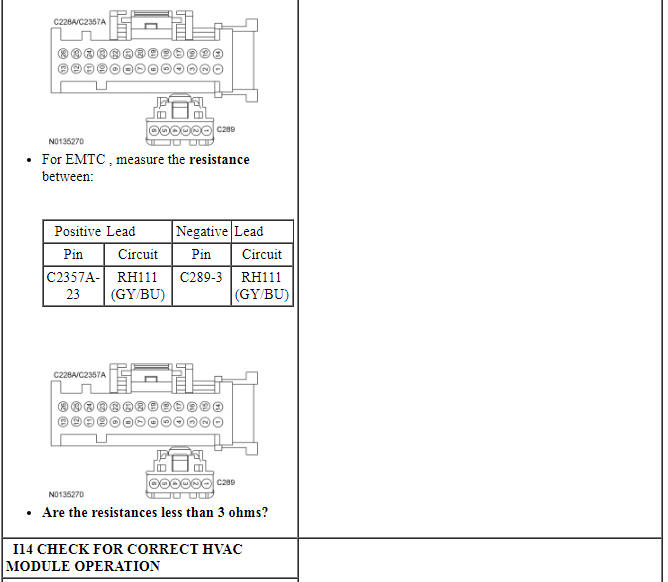
PINPOINT TEST I: THE AIR INLET DOOR IS INOPERATIVE
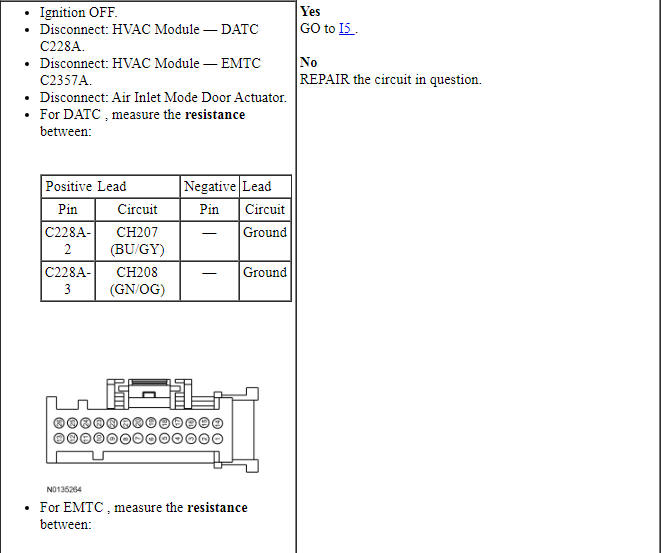
NOTE: Access to the connector in the following step is difficult. Before carrying out this step, visually inspect the actuator and its harness for obvious damage. If no damage is evident, proceed with the test.
Pinpoint Test J: Incorrect/Erratic Direction of Airflow From Outlets
Diagnostic Overview
Diagnostics in this manual assume a certain skill level and knowledge of Ford-specific diagnostic practices. Refer to Diagnostic Methods in Section 100-00 for information about these practices.
Refer to Wiring Diagrams Cell 54, Manual Climate Control System for schematic and connector information.
Refer to Wiring Diagrams Cell 55, Automatic Climate Control System for schematic and connector information.
Normal Operation and Fault Conditions
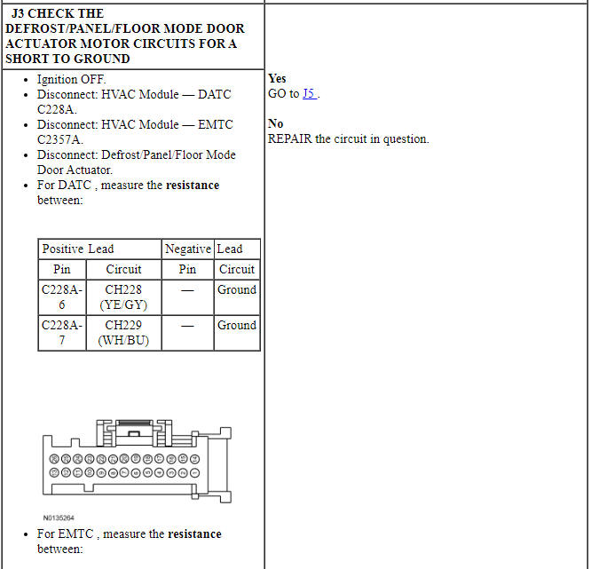
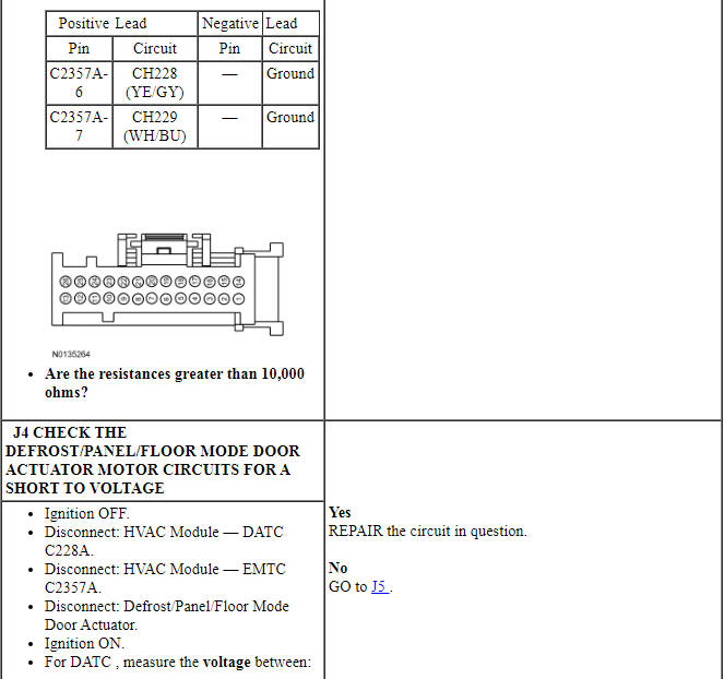
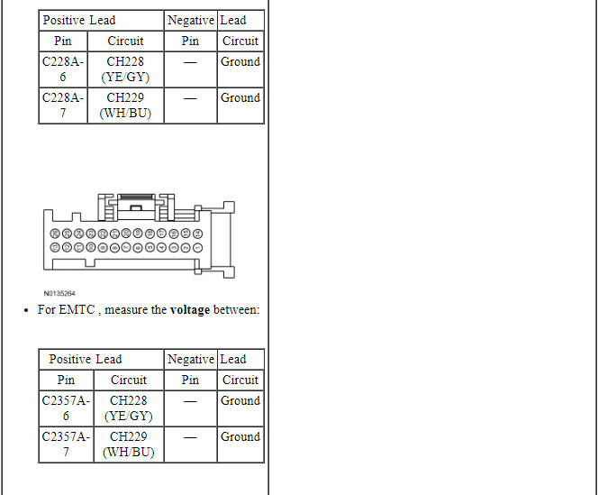
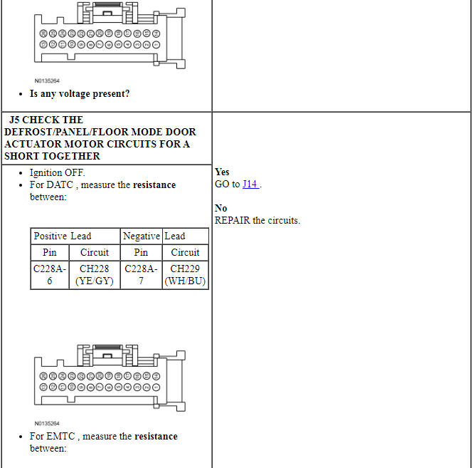
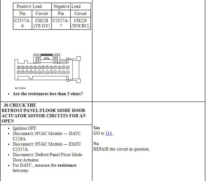
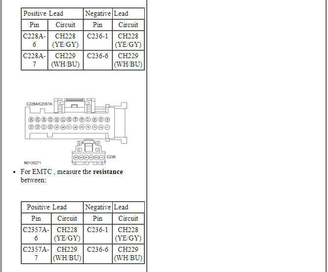
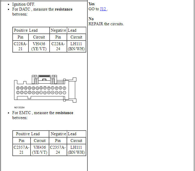
To rotate the defrost/panel/floor mode door actuator, the HVAC module supplies voltage and ground to the defrost/panel/floor mode door actuator motor through the actuator motor circuits. To reverse the defrost/panel/floor mode door actuator rotation, the HVAC module reverses the voltage and ground circuits.
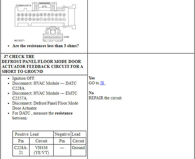
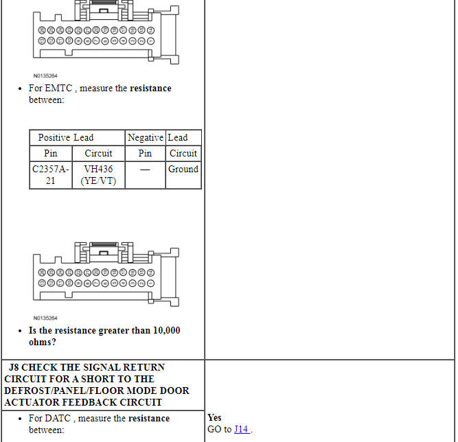
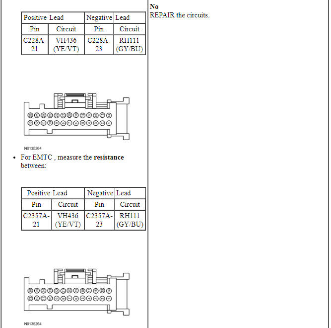
The defrost/panel/floor mode door actuator feedback resistor is supplied a 5-volt reference voltage and ground from the HVAC module. The HVAC module measures the resistance on the defrost/panel/floor mode door actuator feedback circuit to determine the defrost/panel/floor mode door actuator position by the position of the actuator feedback resistor wiper arm.
During an actuator calibration cycle, the HVAC module drives the defrost/panel/floor mode door until the door reaches both internal stops in the HVAC case. If the defrost/panel/floor mode door is temporarily obstructed or binding during a calibration cycle, the HVAC module may interpret this as the actual end of travel for the door. When this condition occurs and the HVAC module commands the actuator to its end of travel, the airflow may not be from the expected outlets.
DTC Fault Trigger Conditions
-
Possible Sources
- Wiring, terminals or connectors
- Defrost/panel/floor mode door actuator
- HVAC module
- FCIM
- Defrost/panel/floor mode door binding or stuck
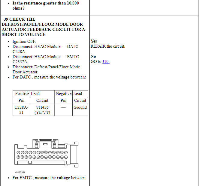
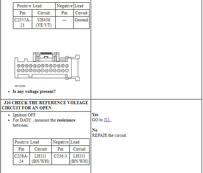
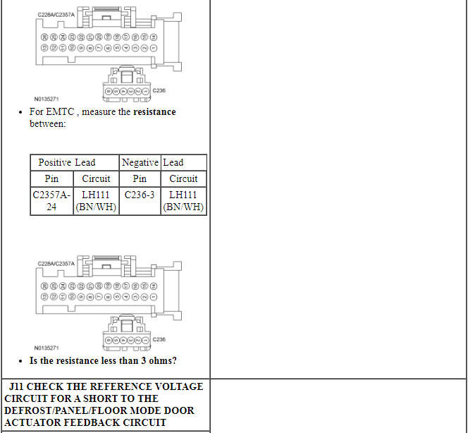
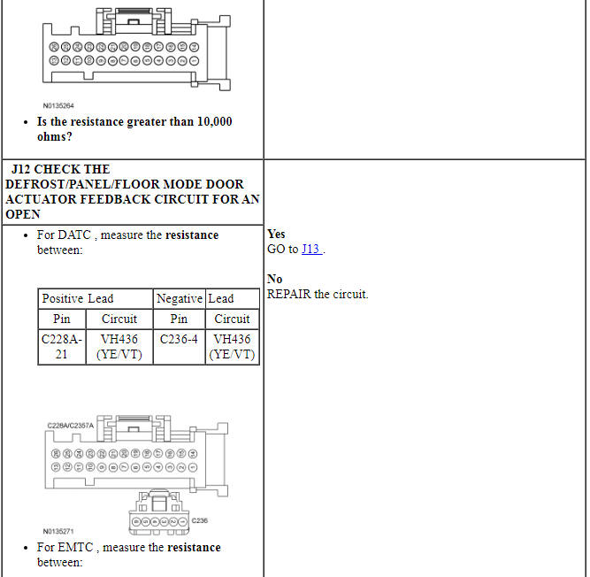
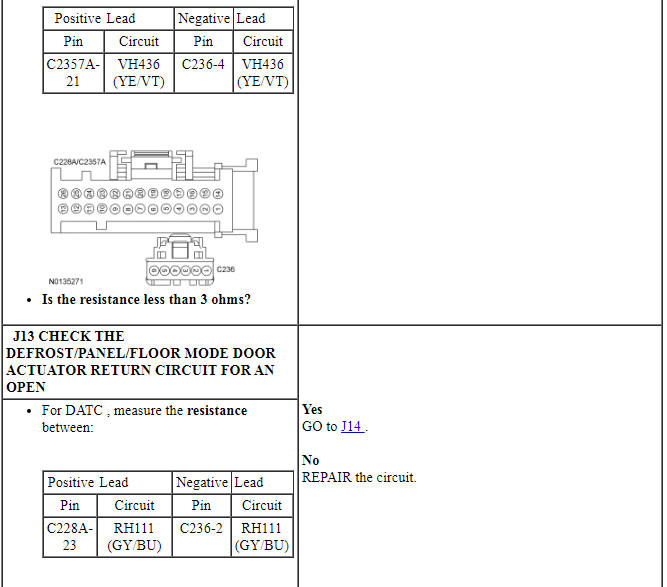
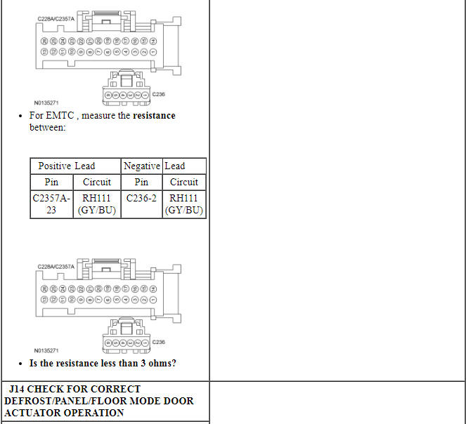
PINPOINT TEST J: INCORRECT/ERRATIC DIRECTION OF AIRFLOW FROM OUTLETS
NOTE: Access to the defrost/panel/floor mode door actuator motor connector in this pinpoint test is difficult. Before disconnecting the defrost/panel/floor mode door actuator motor connector, visually inspect the actuator and its harness for obvious damage. If no damage is evident, proceed with the test.
Pinpoint Test K: Insufficient, Erratic or No Heat
Diagnostic Overview
Diagnostics in this manual assume a certain skill level and knowledge of Ford-specific diagnostic practices. Refer to Diagnostic Methods in Section 100-00 for information about these practices.
Normal Operation and Fault Conditions
Warm coolant flows from the engine through the heater core and back to the engine. Proper coolant temperatures are critical for good heater performance.
-
Possible Sources
- Plugged or partially plugged heater core
- Low engine coolant level
- Temperature blend door actuator(s)
- Temperature blend door(s) binding or stuck
PINPOINT TEST K: INSUFFICIENT, ERRATIC OR NO HEAT
Pinpoint Test L: The Air Conditioning (A/C) is Inoperative
Diagnostic Overview
Diagnostics in this manual assume a certain skill level and knowledge of Ford-specific diagnostic practices. Refer to Diagnostic Methods in Section 100-00 for information about these practices.
Refer to Wiring Diagrams Cell 54, Manual Climate Control System for schematic and connector information.
Refer to Wiring Diagrams Cell 55, Automatic Climate Control System for schematic and connector information.
Normal Operation and Fault Conditions
When the A/C is requested, the FCIM sends the button press message over the I-CAN to the IPC. The IPC sends the button press message to the BCM over the HS-CAN. The BCM sends the button press message to the HVAC module over the MS-CAN. The HVAC module sends an A/C request message through the MS-CAN to the BCM and the BCM sends the A/C request through the HS-CAN to the PCM.
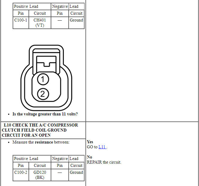
Voltage is provided to the A/C clutch relay coil and switch contacts. When A/C is requested and A/C line pressures allow, a ground is provided to the A/C clutch relay coil from the PCM, energizing the A/C clutch relay. When the PCM energizes the relay, voltage is supplied to the A/C compressor clutch field coil from the relay. Ground is supplied for the A/C compressor clutch field coil.
The evaporator temperature sensor is used for A/C compressor cycling. An accurate evaporator temperature is critical for compressor engagement. The PCM uses the temperature measurement to turn the A/C compressor off before the evaporator temperatures are cold enough to freeze the condensation on the evaporator core.
When an A/C request is received by the PCM, the A/C compressor clutch only engages through the A/C clutch relay if all of the following conditions are met:
- The PCM does not detect excessively high or low refrigerant pressure from the A/C pressure transducer.
- The PCM does not detect excessively high engine coolant temperature.
- The PCM does not detect an ambient air temperature below -1ÂşC (30ÂşF).
- The PCM has not detected a WOT condition.
- The HVAC module does not detect an evaporator temperature below 7.5ÂşC (45.5ÂşF).
-
Possible Sources
- Fuse
- Wiring, terminals or connectors
- A/C system discharged/low charge
- PCM
- HVAC module
- FCIM
- Evaporator temperature sensor
- A/C pressure transducer
- A/C compressor
- A/C clutch relay
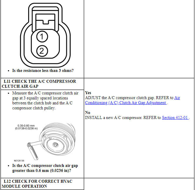
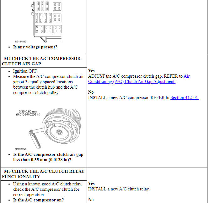
- A/C compressor clutch air gap
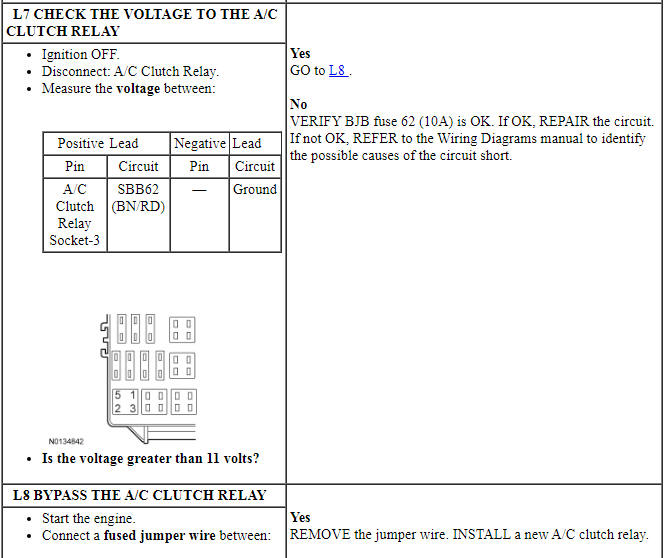
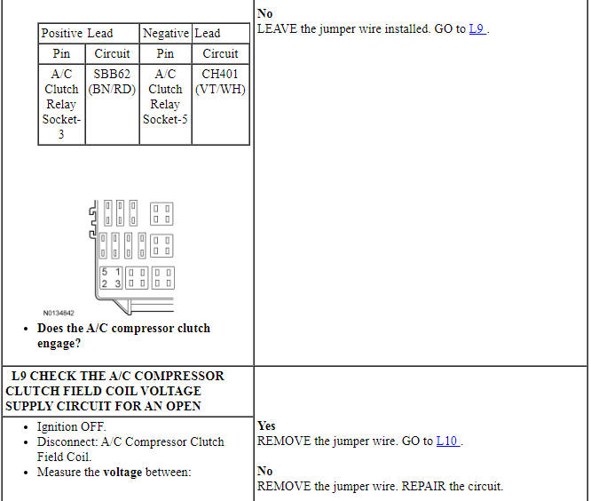
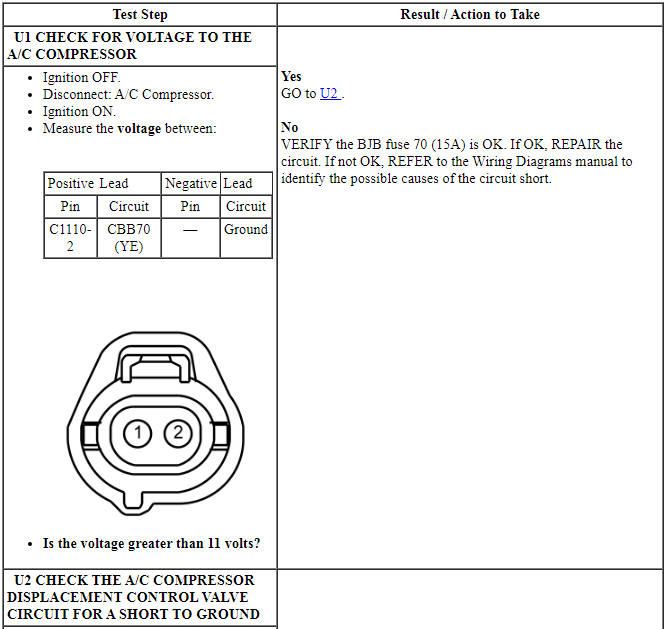
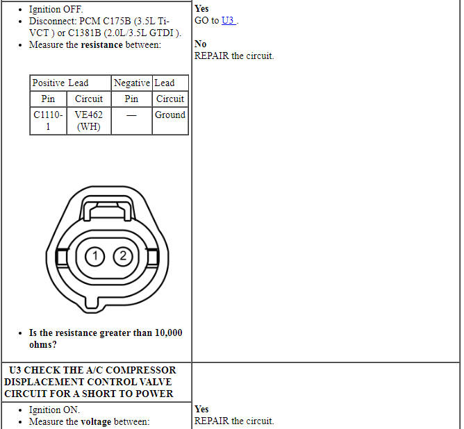
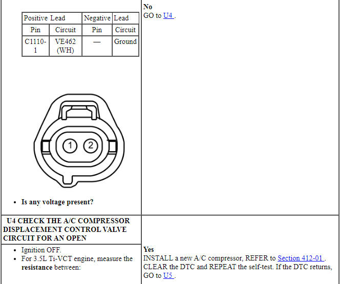
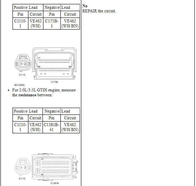
PINPOINT TEST L: THE AIR CONDITIONING (A/C) IS INOPERATIVE
Pinpoint Test M: The Air Conditioning (A/C) is Always On - A/C Compressor Does Not Cycle
Diagnostic Overview
Diagnostics in this manual assume a certain skill level and knowledge of Ford-specific diagnostic practices. Refer to Diagnostic Methods in Section 100-00 for information about these practices.
Refer to Wiring Diagrams Cell 54, Manual Climate Control System for schematic and connector information.
Refer to Wiring Diagrams Cell 55, Automatic Climate Control System for schematic and connector information.
Normal Operation and Fault Conditions
When the A/C is requested, the FCIM sends the button press message over the I-CAN to the IPC. The IPC sends the button press message to the BCM over the HS-CAN. The BCM sends the button press message to the HVAC module over the MS-CAN. The HVAC module sends an A/C request message through the MS-CAN to the BCM and the BCM sends the A/C request through the HS-CAN to the PCM.
Voltage is provided to the A/C clutch relay coil and switch contacts. When A/C is requested and A/C line pressures allow, a ground is provided to the A/C clutch relay coil from the PCM, energizing the A/C clutch relay. When the PCM energizes the relay, voltage is supplied to the A/C compressor clutch field coil from the relay. Ground is supplied for the A/C compressor clutch field coil.
The evaporator temperature sensor is used for A/C compressor cycling. An accurate evaporator temperature is critical for compressor engagement. The PCM uses the temperature measurement to turn the A/C compressor off before the evaporator temperatures are cold enough to freeze the condensation on the evaporator core.
-
Possible Sources
- Wiring, terminals or connectors
- A/C clutch relay
- A/C compressor clutch air gap
- PCM
-
Visual Inspection and Diagnostic Pre-checks
- Inspect loose or corroded PCM and A/C clutch relay connections.
PINPOINT TEST M: THE AIR CONDITIONING (A/C) IS ALWAYS ON - A/C COMPRESSOR DOES NOT CYCLE
Pinpoint Test N: The Air Conditioning (A/C) is Always On - A/C Mode Always Commanded ON
Diagnostic Overview
Diagnostics in this manual assume a certain skill level and knowledge of Ford-specific diagnostic practices. Refer to Diagnostic Methods in Section 100-00 for information about these practices.
Refer to Wiring Diagrams Cell 54, Manual Climate Control System for schematic and connector information.
Refer to Wiring Diagrams Cell 55, Automatic Climate Control System for schematic and connector information.
Normal Operation and Fault Conditions
When the A/C is requested, the FCIM sends the button press message over the I-CAN to the IPC. The IPC then sends the button press message to the BCM over the HS-CAN. The BCM sends the button press message to the HVAC module over the MS-CAN. The HVAC module sends an A/C request message through the MS-CAN to the BCM and the BCM sends the A/C request through the HS-CAN to the PCM.
DTC Fault Trigger Conditions
-
Possible Sources
- Wiring, terminals or connectors
- FCIM
- PCM
- HVAC module
-
Visual Inspection and Diagnostic Pre-checks
- Inspect loose or corroded PCM or HVAC module connections.
PINPOINT TEST N: THE AIR CONDITIONING (A/C) IS ALWAYS ON - A/C MODE ALWAYS COMMANDED ON
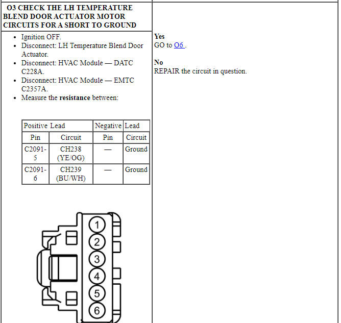
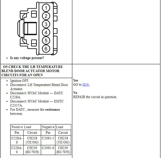
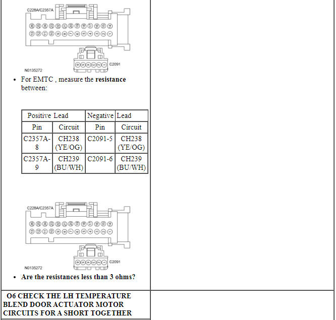
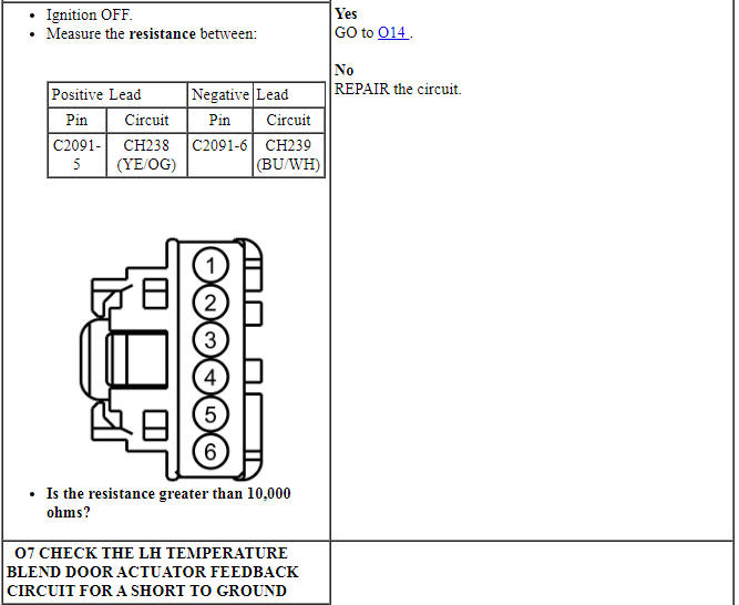
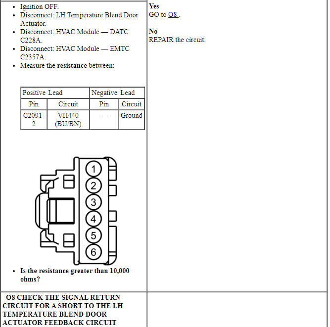
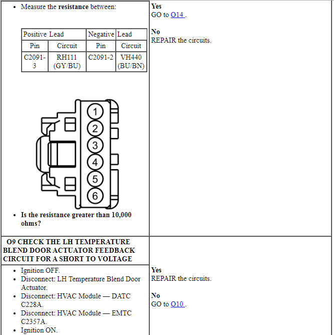
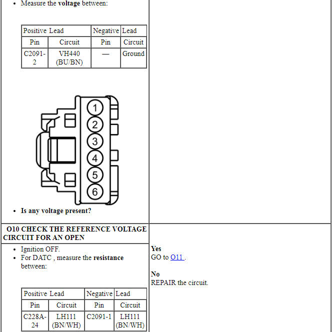
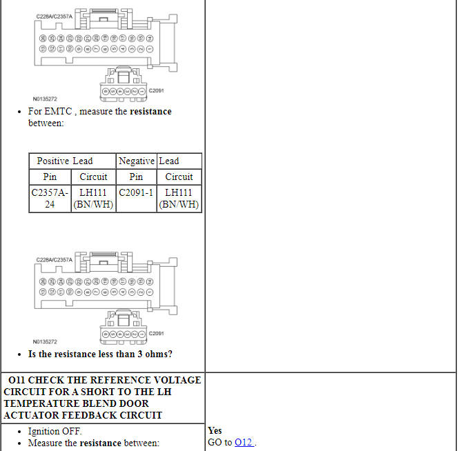
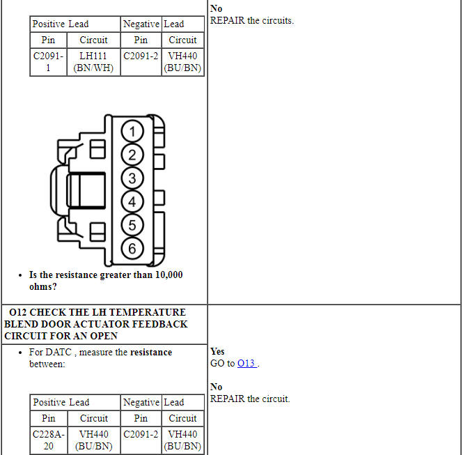
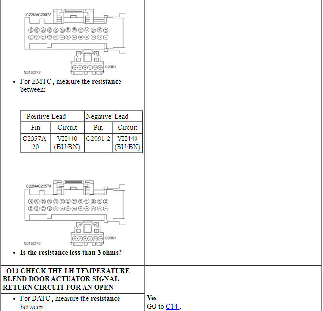
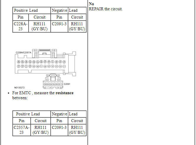
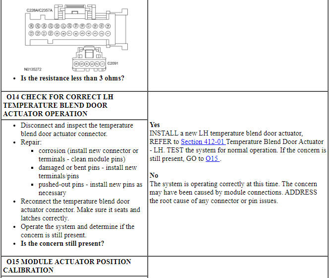
Pinpoint Test O: Temperature Control is Inoperative/Does Not Operate Correctly - LH
Diagnostic Overview
Diagnostics in this manual assume a certain skill level and knowledge of Ford-specific diagnostic practices. Refer to Diagnostic Methods in Section 100-00 for information about these practices.
Refer to Wiring Diagrams Cell 54, Manual Climate Control System for schematic and connector information.
Refer to Wiring Diagrams Cell 55, Automatic Climate Control System for schematic and connector information.
Normal Operation and Fault Conditions
To rotate the temperature blend door actuator, the HVAC module supplies voltage and ground to the temperature blend door actuator through the door actuator motor circuits. To reverse the temperature blend door actuator rotation, the HVAC module reverses the voltage and ground circuits.
The temperature blend door actuator feedback resistors are supplied a ground from the HVAC module by the temperature blend door actuator return circuits and a 5-volt reference voltage on the temperature blend door actuator reference circuits. The HVAC module reads the voltage on the temperature blend door actuator feedback circuits to determine the temperature blend door actuator position by the position of the actuator feedback resistor wiper arm.
During an actuator calibration cycle, the HVAC module drives the temperature blend door until the door reaches both internal stops in the HVAC case. If the temperature blend door is temporarily obstructed or binding during a calibration cycle, the HVAC module may interpret this as the actual end of travel for the door. When this condition occurs and the HVAC module commands the actuator to its end of travel, the airflow may not be the expected temperature.
DTC Fault Trigger Conditions
-
Possible Sources
- Wiring, terminals or connectors
- Temperature blend door actuator
- Temperature blend door is binding or stuck
- HVAC module
- FCIM
PINPOINT TEST O: TEMPERATURE CONTROL IS INOPERATIVE/DOES NOT OPERATE CORRECTLY - LH

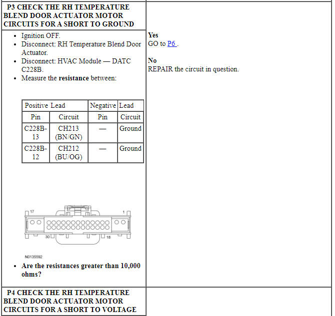
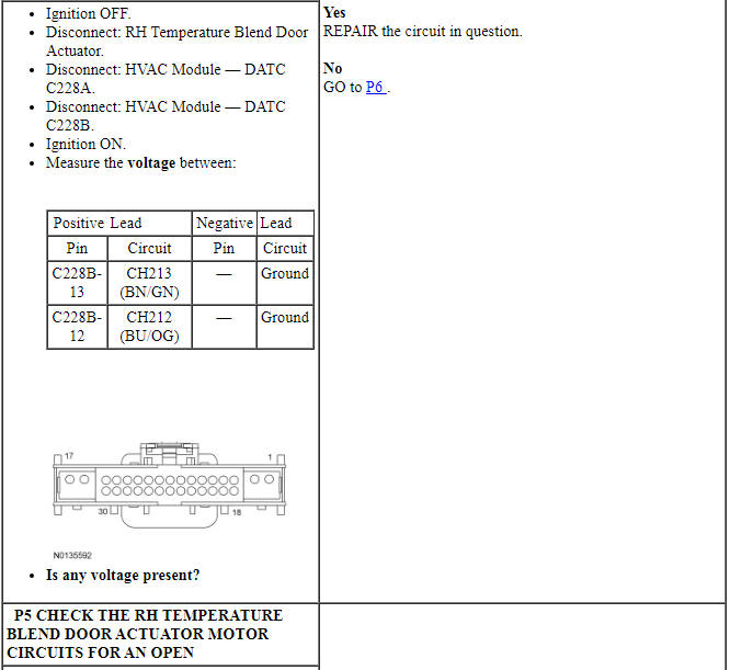
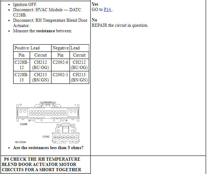
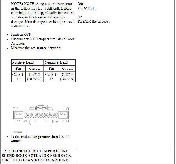
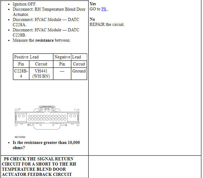
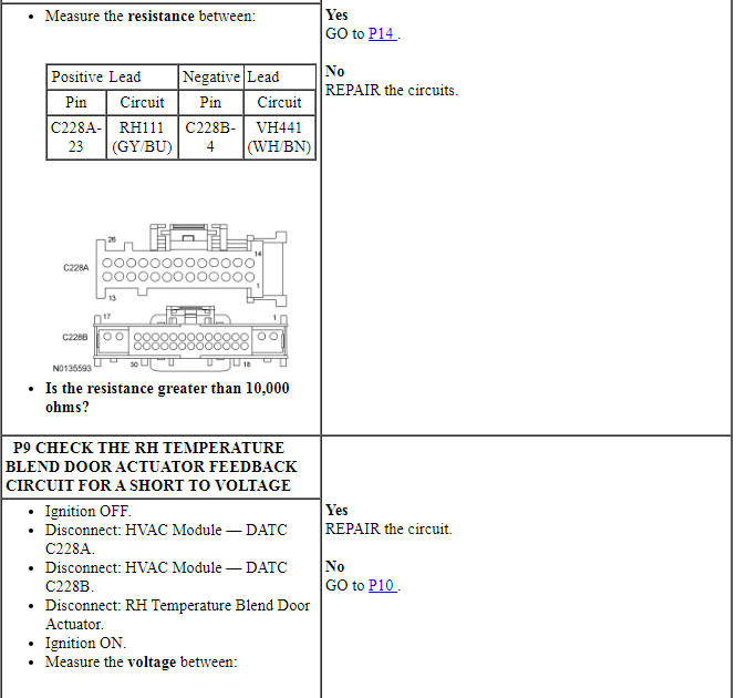
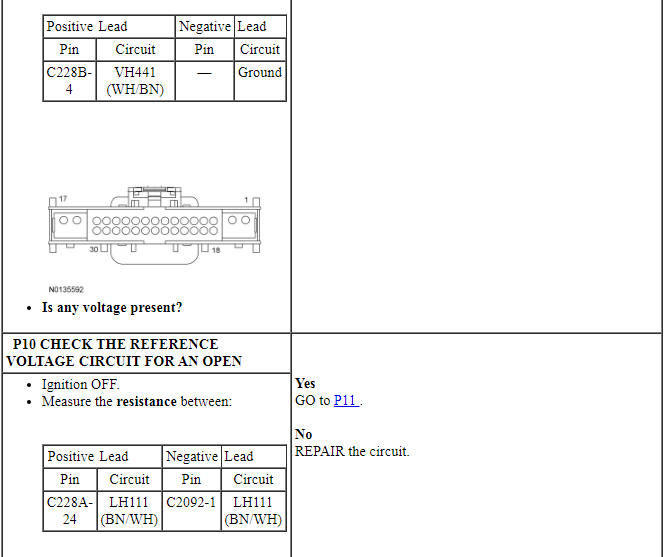
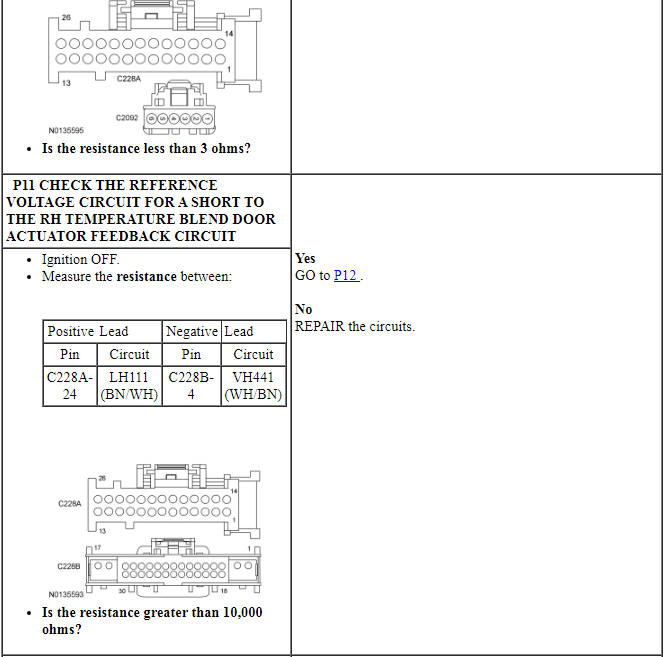
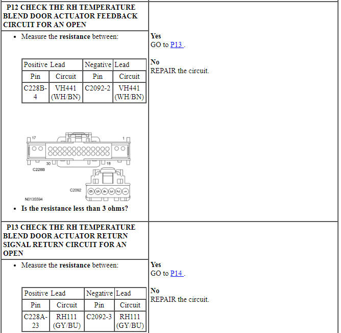
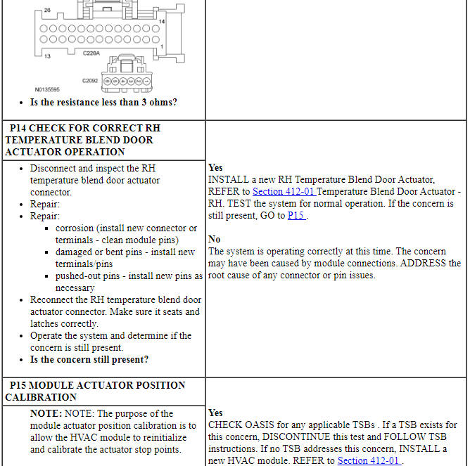
Pinpoint Test P: Temperature Control is Inoperative/Does Not Operate Correctly - RH
Diagnostic Overview
Diagnostics in this manual assume a certain skill level and knowledge of Ford-specific diagnostic practices. Refer to Diagnostic Methods in Section 100-00 for information about these practices.
Refer to Wiring Diagrams Cell 55, Automatic Climate Control System for schematic and connector information.
Normal Operation and Fault Conditions
To rotate the temperature blend door actuator, the HVAC module supplies voltage and ground to the temperature blend door actuator through the door actuator motor circuits. To reverse the temperature blend door actuator rotation, the HVAC module reverses the voltage and ground circuits.
The temperature blend door actuator feedback resistors are supplied a ground from the HVAC module by the temperature blend door actuator return circuits and a 5-volt reference voltage on the temperature blend door actuator reference circuits. The HVAC module reads the voltage on the temperature blend door actuator feedback circuits to determine the temperature blend door actuator position by the position of the actuator feedback resistor wiper arm.
During an actuator calibration cycle, the HVAC module drives the temperature blend door until the door reaches both internal stops in the HVAC case. If the temperature blend door is temporarily obstructed or binding during a calibration cycle, the HVAC module may interpret this as the actual end of travel for the door. When this condition occurs and the HVAC module commands the actuator to its end of travel, the airflow may not be the expected temperature.
DTC Fault Trigger Conditions
-
Possible Sources
- Wiring, terminals or connectors
- Temperature blend door actuator
- Temperature blend door is binding or stuck
- HVAC module
- FCIM
PINPOINT TEST P: Pinpoint Test P: TEMPERATURE CONTROL IS INOPERATIVE/DOES NOT OPERATE CORRECTLY - RH
Pinpoint Test Q: The Blower Motor is Inoperative
Diagnostic Overview
Diagnostics in this manual assume a certain skill level and knowledge of Ford-specific diagnostic practices. Refer to Diagnostic Methods in Section 100-00 for information about these practices.
Refer to Wiring Diagrams Cell 54, Manual Climate Control System for schematic and connector information.
Refer to Wiring Diagrams Cell 55, Automatic Climate Control System for schematic and connector information.
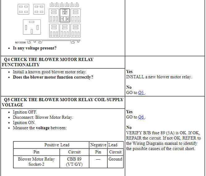
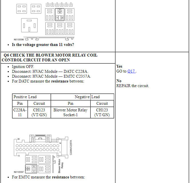
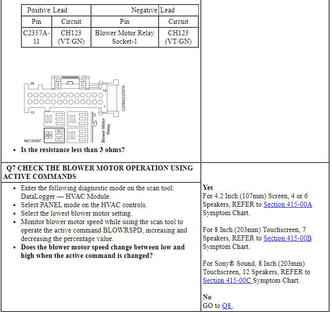
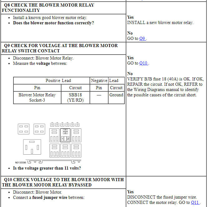
Normal Operation and Fault Conditions
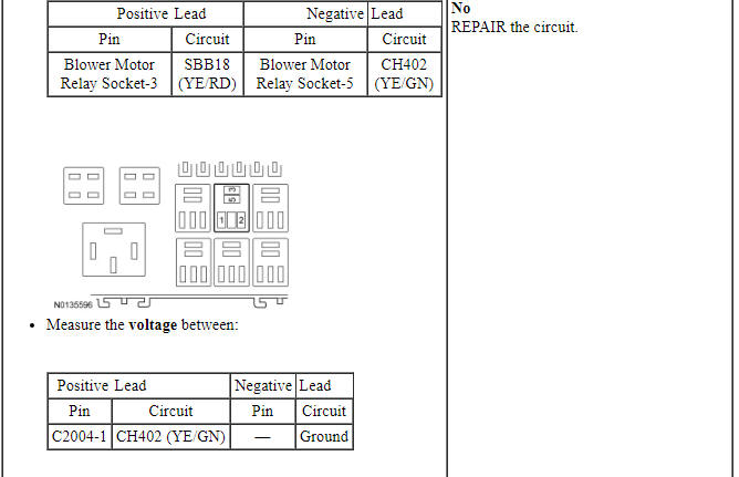
Ground is provided for the blower motor speed control. Voltage is provided to the blower motor relay coil and switch contacts. When the blower motor relay coil receives a ground from the HVAC module, the relay coil is energized and voltage is delivered from the blower motor relay to the blower motor. A varying ground for the blower motor is provided from the blower motor speed control. The HVAC module provides a blower target speed signal to the blower motor speed control to control the blower speed. The actual blower speed signal is provided to the HVAC module from the blower motor speed control.
DTC Fault Trigger Conditions
-
Possible Sources
- Fuse
- Wiring, terminals or connectors
- Blower motor relay
- Blower motor speed control
- Blower motor
- HVAC module
- FCIM
-
Visual Inspection and Diagnostic Pre-checks
- Inspect loose or corroded blower motor relay connections.
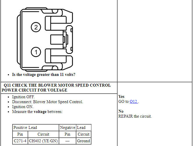
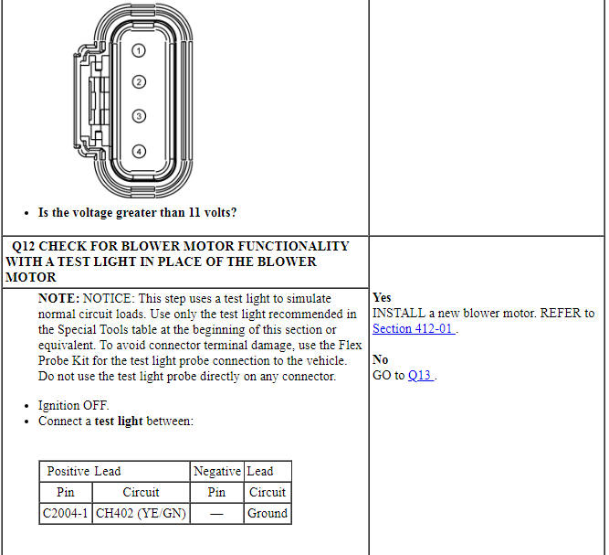
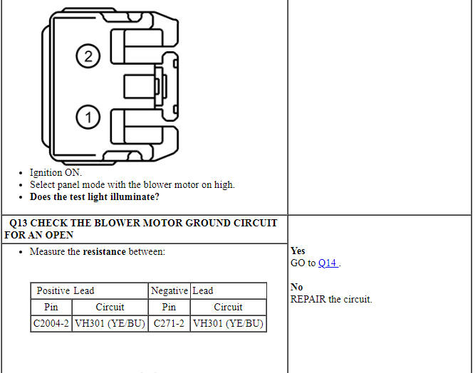
PINPOINT TEST Q: Pinpoint Test Q: THE BLOWER MOTOR IS INOPERATIVE
Pinpoint Test R: The Blower Motor Does Not Operate Correctly
Diagnostic Overview
Diagnostics in this manual assume a certain skill level and knowledge of Ford-specific diagnostic practices. Refer to Diagnostic Methods in Section 100-00 for information about these practices.
Refer to Wiring Diagrams Cell 54, Manual Climate Control System for schematic and connector information.
Refer to Wiring Diagrams Cell 55, Automatic Climate Control System for schematic and connector information.
Normal Operation and Fault Conditions
Voltage is provided to the blower motor relay coil and switch contacts. When the blower motor relay coil receives a ground from the HVAC module, the relay coil is energized and voltage is delivered from the blower motor relay to the blower motor. A varying ground for the blower motor is provided from the blower motor speed control. Ground is provided for the blower motor speed control. The HVAC module provides a blower target speed signal to the blower motor speed control to control the blower speed. The actual blower speed signal is provided to the HVAC module from the blower motor speed control.
DTC Fault Trigger Conditions
-
Possible Sources
- Wiring, terminals or connectors
- Blower motor speed control
- HVAC module
- FCIM
-
Visual Inspection and Diagnostic Pre-checks
- Inspect loose or corroded BCM, blower motor speed control and HVAC module connections.
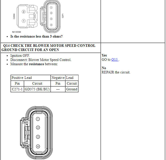
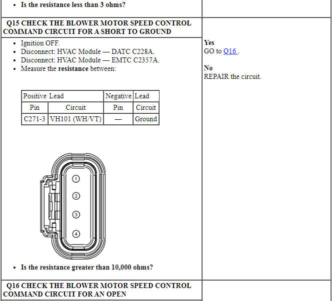
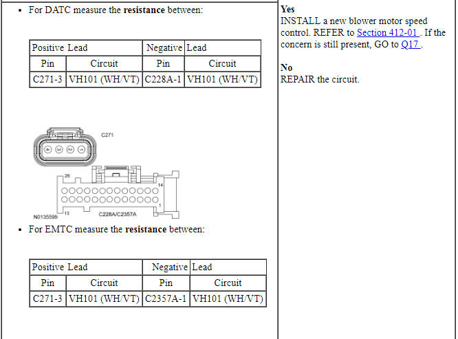
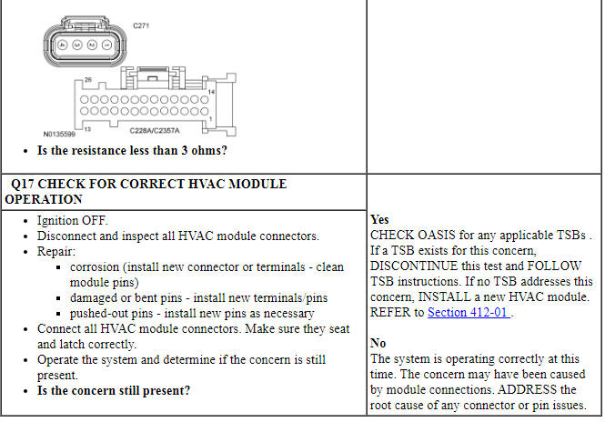
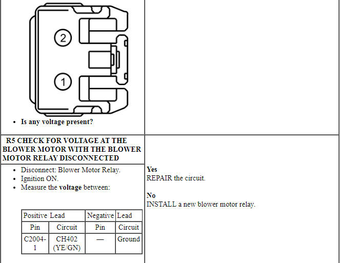
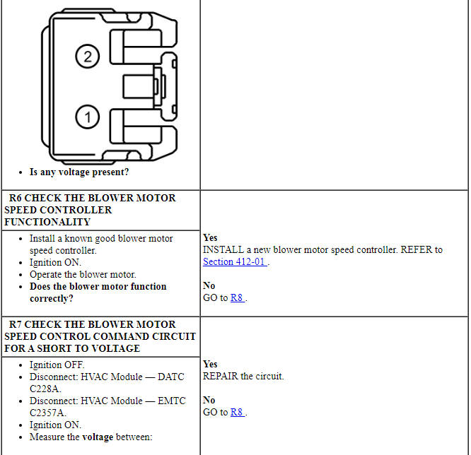
PINPOINT TEST R: THE BLOWER MOTOR DOES NOT OPERATE CORRECTLY

Pinpoint Test S: DTC U0140:00
Diagnostic Overview
Diagnostics in this manual assume a certain skill level and knowledge of Ford-specific diagnostic practices. Refer to Diagnostic Methods in Section 100-00 for information about these practices.
DTC Fault Trigger Conditions
-
Possible Sources
- BCM
- HVAC module
-
Visual Inspection and Diagnostic Pre-checks
- Inspect loose or corroded BCM and HVAC module connections.
PINPOINT TEST S: DTC U0140:00
Pinpoint Test T: DTCs B1A61:15, B1A63:15 and B1A64:15
Diagnostic Overview
Diagnostics in this manual assume a certain skill level and knowledge of Ford-specific diagnostic practices. Refer to Diagnostic Methods in Section 100-00 for information about these practices.
Refer to Wiring Diagrams Cell 54, Manual Climate Control System for schematic and connector information.
Refer to Wiring Diagrams Cell 55, Automatic Climate Control System for schematic and connector information.
Normal Operation and Fault Conditions
The in-vehicle temperature/humidity sensor receives a ground from the HVAC module. The sensor varies its resistance with the temperature. As the temperature rises, the resistance falls. As the temperature falls the resistance rises. The HVAC module measures this resistance to determine the temperature at the sensor. The autolamp/sunload sensor is grounded. As the light applied to the sensor changes, the HVAC module detects the change through the RH and LH feedback circuits.
The HVAC module internally ties the in-vehicle temperature/humidity sensor and the LH and RH autolamp/sunload sensor feedback short to voltage diagnostics together. In the event any of the 3 feedback circuits are shorted to voltage all three DTCs set.
DTC Fault Trigger Conditions
-
Possible Sources
- Wiring, terminals or connectors
- HVAC module
-
Visual Inspection and Diagnostic Pre-checks
- Make sure the in-vehicle temperature/humidity sensor harness is not chaffed.
PINPOINT TEST T: DTCs B1A61:15, B1A63:15 AND B1A64:15
Pinpoint Test U: DTC P06A0
Diagnostic Overview
Diagnostics in this manual assume a certain skill level and knowledge of Ford-specific diagnostic practices. Refer to Diagnostic Methods in Section 100-00 for information about these practices.
Refer to Wiring Diagrams Cell 54, Manual Climate Control System for schematic and connector information.
Refer to Wiring Diagrams Cell 55, Automatic Climate Control System for schematic and connector information.
Normal Operation and Fault Conditions
The externally controlled variable displacement compressor is electronically controlled by the PCM. The PCM pulse width modulates the ground to the externally controlled variable displacement compressor to change the displacement of the A/C compressor.
DTC Fault Trigger Conditions
-
Possible Sources
- Fuse
- Wiring, terminals or connectors
- A/C compressor
- PCM
-
Visual Inspection and Diagnostic Pre-checks
- Inspect loose or corroded PCM and A/C compressor connections.
PINPOINT TEST U: DTC P06A0
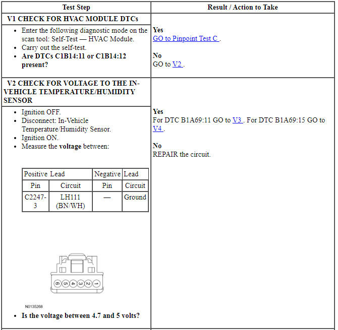
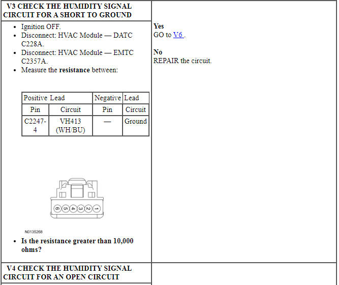
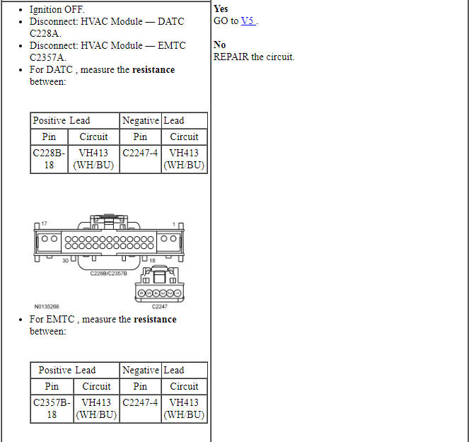
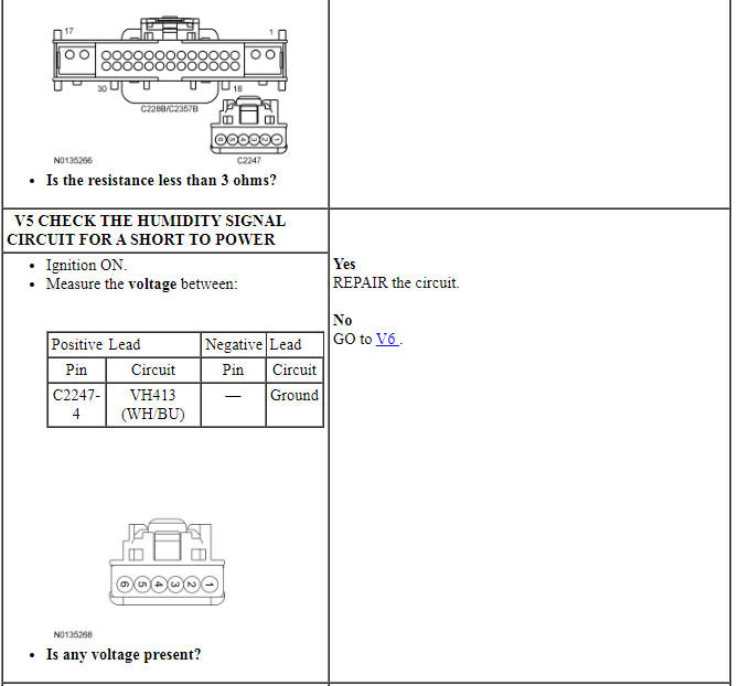
Pinpoint Test V: DTCs B1A69:11 and B1A69:15
Diagnostic Overview
Diagnostics in this manual assume a certain skill level and knowledge of Ford-specific diagnostic practices. Refer to Diagnostic Methods in Section 100-00 for information about these practices.
Refer to Wiring Diagrams Cell 54, Manual Climate Control System for schematic and connector information.
Refer to Wiring Diagrams Cell 55, Automatic Climate Control System for schematic and connector information.
Normal Operation and Fault Conditions
The humidity sensor receives power from the HVAC reference voltage circuit. The sensor modifies voltage depending on the humidity in the air. The HVAC module translates the voltage signal into a humidity reading.
DTC Fault Trigger Conditions
-
Possible Sources
- Wiring, terminals or connectors
- In-vehicle temperature sensor/humidity sensor
- HVAC module
-
Visual Inspection and Diagnostic Pre-checks
- Make sure the in-vehicle temperature/humidity sensor harness is not chaffed.
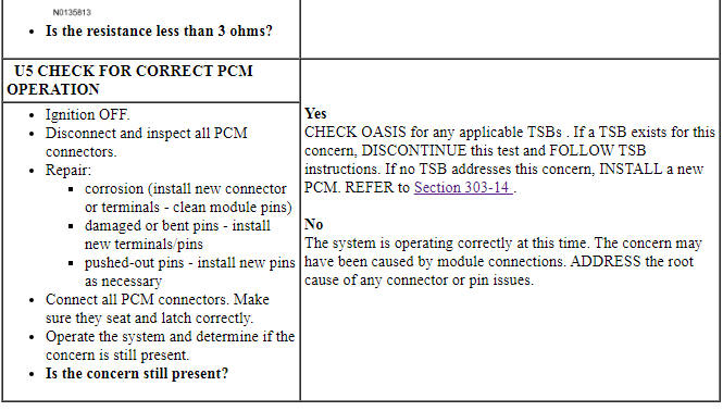
PINPOINT TEST V: DTCs B1A69:11 AND B1A69:15
Component Tests
Air Inlet Door Actuator

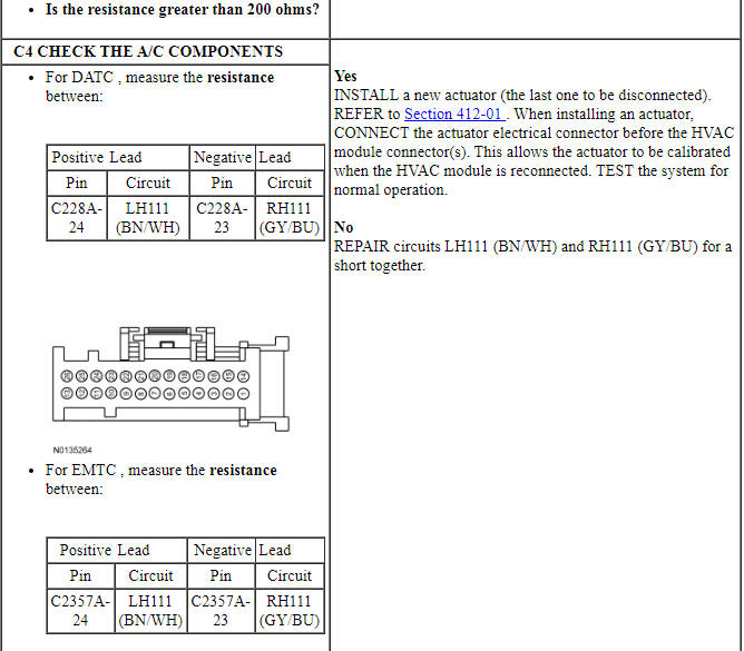
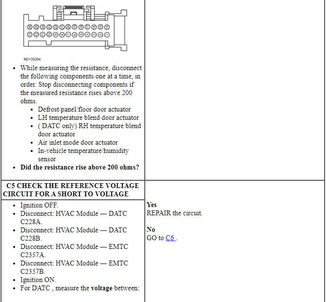
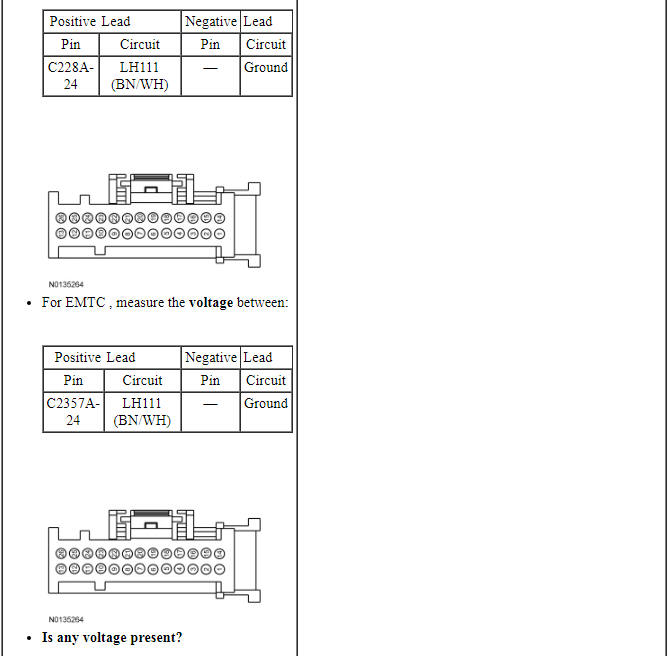
Blend Door Actuator - DATC
Blend Door Actuator - EMTC

Defrost/Panel/Floor Mode Door Actuator
Evaporator Temperature Sensor
In-Vehicle Temperature/Humidity Sensor
Heater Core
- NOTE: If a heater core leak is suspected, test the heater core by
following the plugged heater core component test before the heater core
pressure test. Carry out a system inspection by checking the heater system
thoroughly as follows:
Inspect for evidence of coolant leakage at the heater hose to heater core attachments. A coolant leak in the heater hose could follow the heater core tube to the heater core and appear as a leak in the heater core.
- NOTE: Spring-type clamps are installed as original equipment.
Installation and overtightening of non-specified clamps can cause leakage at
the heater hose connection and damage the heater core.
Check the integrity of the heater hose clamps.
Heater Core - Plugged
- Verify the engine coolant is at the correct level.
- Start the engine and turn on the heater.
- When the engine coolant reaches operating temperature, check the heater core inlet and outlet hoses to see if they are hot.
- If the outlet only is not hot:
- the heater core may have an air pocket.
- the heater core may be plugged.
- If the inlet only is not hot:
- the thermostat may not be working correctly.
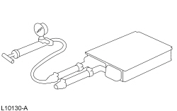
Heater Core - Pressure Test
Use the Pressure Test Kit to carry out the pressure test.
- NOTE: Due to space limitations, a bench test may be necessary for
pressure testing.
Drain the coolant from the cooling system.
- Disconnect the heater hoses from the heater core.
- Install a short piece of heater hose, approximately 101 mm (4 in) long on each heater core tube.
- Fill the heater core and heater hoses with water and install the plug BT-7422-B and the adapter BT-7422-A from the Pressure Test Kit. Secure the heater hoses, plug and adapter with hose clamps.
- Attach the pump and gauge assembly from the Pressure Test Kit to the adapter.
- Close the bleed valve at the base of the gauge. Pump 138 kPa (20 psi) of air pressure into the heater core.
- Observe the pressure gauge for a minimum of 3 minutes.
- If the pressure drops, check the heater hose connections to the core tubes for leaks. If the heater hoses do not leak, remove the heater core from the vehicle and carry out the bench test.
Heater Core - Bench Test
- Remove the heater core from the vehicle.
- Drain all of the coolant from the heater core.
- Connect the 101 mm (4 in) test heater hoses with plug and adapter to the core tubes. Then connect the Pressure Test Kit to the adapter.
- Apply 138 kPa (20 psi) of air pressure to the heater core. Submerge the heater core in water.
- If a leak is observed, install a new heater core.
Evaporator/Condenser Core - On-Vehicle Leak Test
- Discharge and recover the refrigerant. Refer to Air Conditioning (A/C) System Recovery, Evacuation and Charging in this section.
- Disconnect the suspect evaporator or condenser core from the A/C system.
- Clean the manifold fittings.
- Connect the appropriate test fittings from the A/C Flush Adapter Kit to the condenser or evaporator core tube connections.
- NOTE: The automatic shut-off valves on some gauge set hoses do
not open when connected to the test fittings. If available, use hoses
without shut-off valves. If hoses with shut-off valves are used, make sure
the valve opens when attached to the test fittings or install an adapter
that will activate the valve. The test is not valid if the shut-off valve
does not open.
Connect the red and blue hoses from the R-134a Manifold Gauge Set to the test fittings on the evaporator or condenser core. Connect the yellow hose to a known good vacuum pump.
- Open both gauge set valves and start the vacuum pump. Allow the vacuum pump to operate for a minimum of 45 minutes after the gauge set low pressure gauge indicates 101 kPa (30 in-Hg). The 45-minute evacuation is necessary to remove any refrigerant from oil left in the evaporator or condenser core. If the refrigerant is not completely removed from the oil, outgassing will degrade the vacuum and appear as a refrigerant leak.
- If the low pressure gauge reading will not drop to 101 kPa (30 in-Hg) when the valves on the gauge and manifold set are open and the vacuum pump is operating, close the gauge set valves and observe the low pressure gauge. If the pressure rises rapidly to zero, a large leak is indicated. Recheck the test fitting connections and gauge set connections before installing a new evaporator or condenser core.
- After evacuating for 45 minutes, close the gauge set valves and stop the
vacuum pump. Observe the low pressure gauge; it should remain at the 101 kPa
(30 in-Hg) mark.
- If the low pressure gauge reading rises 34 or more kPa (10 or more in-Hg) of vacuum from the 101 kPa (30 in-Hg) position in 10 minutes, a leak is indicated.
- If a very small leak is suspected, wait 30 minutes and observe the vacuum gauge.
- If a small amount of vacuum is lost, operate the vacuum pump with gauge valves open for an additional 30 minutes to remove any remaining refrigerant from the oil in the evaporator or condenser core. Then recheck for loss of vacuum.
- If a very small leak is suspected, allow the system to sit overnight with vacuum applied and check for vacuum loss.
- If the evaporator or condenser core does leak, as verified by the above procedure, install a new evaporator or condenser core.
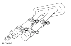
A/C Compressor - External Leak Test
- Install the adapter from the A/C Flush Adapter Kit on the port of the A/C compressor, using the existing manifold retaining bolt.
- Connect the high and low pressure lines of a manifold gauge set or a refrigerant recovery/recycling station to the corresponding fittings on the adapter.
- Attach the center hose of a manifold gauge set to a refrigerant container standing in an upright position.
- Open the low pressure gauge valve, the high pressure gauge valve and the valve on the refrigerant container to allow the refrigerant vapor to flow into the A/C compressor.
- Using the Refrigerant Leak Detector, check for leaks at the compressor shaft.
- If an external leak is found, install a new A/C compressor.
- When the leak test is complete, recover the refrigerant from the compressor.
 Specifications, Description and Operation
SPECIFICATIONS
General Specifications
a Manifold gauge set pressures may vary slightly depending on the
distance between the service gauge port valve and the A/C pressure relief valve,
the A/C ...
 General Procedures
Air Conditioning (A/C) Clutch Air Gap Adjustment
Check the A/C clutch air gap at 3 equally spaced places between the
clutch plate and the A/C clutch pulley.
Remove the clutch plate. Add or ...
Other materials:
Diagnosis and Testing
Seating
Special Tool(s)
Medium Speed Controller Area Network (MS-CAN)
This vehicle utilizes a communication system called a Medium Speed Controller
Area Network (MS-CAN). When diagnosing the memory seat, heated seats or climate
controlled seats, use a Vehicle Communication Module (VCM) and Integr ...
Removal and Installation
Hood Latch
Removal and Installation
Remove the upper radiator sight shield.
Remove the 8 screws.
Remove the 4 bolts.
Remove the 2 pin-type retainers.
NOTE: Mark the position of the hood latch prior to removing the
hood latch bolts.Remove the 2 bolts and position t ...
Diagnosis and Testing
Handles, Locks, Latches and Entry Systems
Special Tool(s)
Material
DTC Chart
Diagnostics in this manual assume a certain skill level and knowledge of
Ford-specific diagnostic practices. Refer to Diagnostic Methods in Section
100-00 for information about these practices.
BCM DTC Ch ...
