SPECIFICATIONS
Material
General Specifications
Torque Specifications
DIAGNOSIS AND TESTING
Principles of Operation
Brake System
Applying the brake pedal uses lever action to push a rod into the brake booster, which through the use of vacuum, boosts the force of the rod and then transmits this force to the primary piston in the master cylinder. This produces hydraulic pressure in the master cylinder. This pressure builds in the master cylinder and brake tubes as the brake pedal is applied further. The pressure between the primary and secondary piston forces the secondary piston to compress, building pressure in its circuit. The hydraulic pressure is transmitted by brake fluid through the brake tubes to the ABS Hydraulic Control Unit (HCU), which then distributes that pressure to the individual brake calipers. The brake calipers use hydraulic pressure to apply the pads. The application of the brake pads will cause the rotation of the wheels to slow or stop, depending on how much brake pressure is applied. The parking brakes carry out the same function except that they are mechanically actuated by a cable that connects only to the rear brakes.
Brake Master Cylinder Compensator Ports
The purpose of the compensator ports in the brake master cylinder is to supply additional brake fluid from the master cylinder reservoir when needed by the brake system due to brake lining wear and allow brake fluid to return to the master cylinder reservoir when the brakes are released. The returning brake fluid creates a slight turbulence in the master cylinder reservoir. This is a normal condition and indicates that the compensator ports are not clogged. Clogged compensator ports may cause the brakes to hang up or not fully release.
Red Brake Warning Indicator
The red brake warning indicator alerts the driver to certain conditions that exist in the brake system. The Instrument Cluster (IC) performs a bulb check when the ignition key is turned to the RUN position. The conditions that cause the indicator to illuminate are low brake fluid level, the parking brake is applied or there is a fault in the ABS (if the yellow ABS warning indicator is also illuminated). To diagnose red brake warning indicator concerns, refer to Section 413-01.
Inspection And Verification
Material
WARNING: Do not use any fluid other than clean brake fluid meeting manufacturer's specification. Additionally, do not use brake fluid that has been previously drained. Following these instructions will help prevent system contamination, brake component damage and the risk of serious personal injury.
WARNING: Carefully read cautionary information on product label. For emergency medical information seek medical advice. In the USA or Canada on Ford/Motorcraft products call: 1-800-959-3673. For additional information, consult the product Material Safety Data Sheet (MSDS) if available. Failure to follow these instructions may result in serious personal injury.
NOTICE: Blistering or swelling of rubber brake components can indicate contamination of the brake fluid by a petroleum-based substance. The entire hydraulic brake system must be flushed with clean, specified brake fluid and contaminated rubber components must be replaced to prevent recontamination.
NOTICE: Do not spill brake fluid on painted or plastic surfaces or damage to the surface may occur. If brake fluid is spilled onto a painted or plastic surface, immediately wash the surface with water.
The first indication that something may be wrong in the brake system is a change in the feeling through the brake pedal. The brake warning indicator in the Instrument Cluster (IC) and the brake fluid level in the brake master cylinder reservoir are also indicators of system concerns.
If a wheel is locked and the vehicle must be moved, open a bleeder screw at the locked wheel to let out enough fluid to relieve the pressure. Close the bleeder screw. If multiple wheels are locked, check the brake pedal free play to verify brake pedal is not partially applied. These operations may release the brakes, but will not correct the concern. If this does not relieve the locked wheel condition, repair the locked components before proceeding.
- Verify the customer concern.
- For parking brake concerns, refer to Section 206-05.
- For ABS concerns, refer to Section 206-09.
- For adjustable pedal concerns, refer to Section 206-06.
- For all other concerns, continue with the next step.
- Visually inspect for obvious signs of mechanical or electrical damage.
Visual Inspection Chart
- Visually inspect the suspension system and tires for obvious signs of
wear or damage.
- For suspension system concerns, refer to Section 204-00.
- For tire concerns, refer to Section 204-04.
- If an obvious cause for an observed or reported concern is found, correct the cause (if possible) before proceeding to the next step.
- If the cause is not visually evident, GO to Symptom Chart - Brake System or GO to Symptom Chart - NVH in this section.
Symptom Chart
Symptom Chart - Brake System
Symptom Chart - NVH
NOTE: NVH symptoms should be identified using the diagnostic tools that are available. For a list of these tools, an explanation of their uses and a glossary of common terms, refer to Section 100-04. Since it is possible any one of multiple systems may be the cause of a symptom, it may be necessary to use a process of elimination type of diagnostic approach to pinpoint the responsible system. If this is not the causal system for the symptom, refer back to Section 100-04 for the next likely system and continue diagnosis.
Pinpoint Tests
Pinpoint Test A: Vibration When the Brakes are Applied
Normal Operation
During moderate to heavy braking, noise from the Hydraulic Control Unit (HCU) and pulsation in the brake pedal can be observed. Pedal pulsation coupled with noise during heavy braking or on loose gravel, bumps, wet or snowy surfaces is acceptable and indicates correct functioning of the ABS. Pedal pulsation or steering wheel nibble when the brakes are applied (frequency is proportioned to the vehicle speed) indicates a concern with a brake or suspension component.
PINPOINT TEST A: VIBRATION WHEN THE BRAKES ARE APPLIED
Component Tests
Brake Booster
- Disconnect the brake booster vacuum sensor/check valve from the brake booster and connect a suitable vacuum/pressure tester to the booster side of the vacuum sensor/check valve.
- Apply the parking brake, start the engine and place the transmission in
NEUTRAL.
- Allow the engine to reach normal operating temperature.
- NOTE: Subtract approximately 3.38 kPa (1 in-Hg) from the
specified reading for every 304.8 m (1,000 ft) of elevation above sea level.
Verify that vacuum is available at the vacuum sensor/check valve with engine running at normal idle speed.
- The vacuum gauge should read between 51-74 kPa (15-22 in-Hg).
- If specified vacuum is available, stop the engine, connect the vacuum sensor/check valve and continue with Step 5.
- If specified vacuum is not available, continue with Step 4.
- Disconnect the check valve from the vacuum hose and verify that the
specified vacuum is available at the hose with the engine at idle speed and
the transmission in NEUTRAL.
- If specified vacuum is available, stop the engine, install a new check valve and continue with Step 5.
- For vehicles equipped with a brake vacuum pump, if specified vacuum is not available, inspect the vacuum hose and install new as necessary. If the vacuum hose is ok, install a new vacuum pump. Refer to Section 206-07.
- For vehicles not equipped with a brake vacuum pump, if specified vacuum is not available, stop the engine, connect the vacuum hose to the check valve and refer to Section 303-00 to diagnose the no/low vacuum condition.
- Apply the brake pedal several times to exhaust all vacuum from the system.
- Apply the brake pedal and hold it in the applied position. Start the
engine and verify that the brake pedal moves downward after the engine
starts.
- If the brake pedal moves, the brake booster is operating correctly.
- If the brake pedal does not move, install a new brake booster. Refer to Section 206-07.
- Operate the engine a minimum of 20 seconds at idle. Stop the engine and
let the vehicle stand for 10 minutes, then apply the brake pedal. The brake
pedal feel should be the same as that noted with the engine operating.
- If the brake pedal feels hard (no power assist), install a new brake booster vacuum sensor/check valve and retest.
- If condition still exists, install a new brake booster. Refer to Section 206-07.
- If the brake pedal feels the same as noted with the engine operating, the vacuum sensor/check valve is functioning properly.
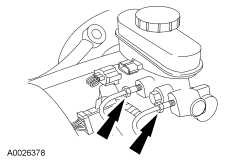
Brake Master Cylinder - Bypass Condition
- Inspect the master cylinder. Refer to Brake System Inspection in this section.
- Disconnect the brake tubes from the master cylinder.
- Plug the outlet ports of the master cylinder.
- NOTE: Make sure that the outlet port plugs do not show signs of
leakage.
Lightly apply the brakes and hold for 10 seconds. Release the brakes and then reapply with heavy force. If brake pedal height cannot be maintained, the brake master cylinder has an internal leak and a new brake master cylinder must be installed.
- If brake pedal height is maintained, reinstall brake tubes and tighten to specifications. Refer to Specifications in this section. After installation, bleed the brake system. Refer to Brake System Bleeding in this section.
Brake Master Cylinder - Compensator Port
- Inspect the master cylinder. Refer to Brake System Inspection in this section.
- With the vehicle in NEUTRAL, position it on a hoist. Refer to Section 100-02.
- Apply and release the brakes.
- With the brakes released, attempt to rotate each wheel and check for any
brake drag.
- If an excessive amount of brake drag exists at multiple wheels, continue to Step 5.
- If an excessive amount of brake drag exists at only one wheel, it indicates a possible seized brake caliper, brake wheel cylinder or parking brake component. Repair or install new components as necessary.
- Check the brake stoplamp switch and the brake pedal free play to verify that the brake pedal is not partially applied.
- Loosen the brake master cylinder nuts and position the brake master cylinder away from the brake booster.
- With the brakes released, attempt to rotate each wheel and check for any
brake drag.
- If the brake drag is no longer present, install a new brake booster. Refer to Section 206-07.
- If the brake drag is still present, install a new master cylinder. Refer to Section 206-06.
GENERAL PROCEDURES
Brake System Inspection
Material
Brake Pads
NOTE: It is not required to install new brake pads when the brake discs are machined.
- Inspect the brake pad friction material for contamination.
- If the friction material shows evidence of contamination, install new brake pads. For additional information, refer to Section 206-03 for front brake pads or Section 206-04 for rear brake pads.
- Inspect and measure the thickness of the brake pad friction material.
For additional information, refer to Specifications in this section.
- Minor surface cracks do not require pad replacement, however, if there are missing chunks or cracks in the lining through to the backing plate, install new brake pads. For additional information, refer to Section 206-03 for front brake pads or Section 206-04 for rear brake pads.
- If the thickness of the friction material is less than the specified thickness, install new brake pads. For additional information, refer to Section 206-03 for front brake pads or Section 206-04 for rear brake pads.
- If the friction material shows taper wear that is not within specifications, install new brake pads and verify the caliper guide pins are functioning correctly. For additional information, refer to Brake Caliper Guide Pins inspection in this section.
Brake Discs
NOTICE: Using an impact tool without a torque socket will lead to unevenly tightened wheel nuts. This causes brake disc on-vehicle lateral runout and brake roughness.
- Inspect the brake discs and measure the brake disc thickness. Record the
measurement, refer to Specifications in this section.
- If the brake disc is cracked or otherwise damaged, install a new brake disc. For additional information, refer to Section 206-03 for front brakes or Section 206-04 for rear brakes.
- If the measurement is below the minimum thickness specification, install a new brake disc. For additional information, refer to Section 206-03 for front brakes or Section 206-04 for rear brakes.
- If the diagnosis has revealed vibration in the steering wheel, seat or pedal while braking that varies with vehicle speed, machine the brake disc. Heavily scored brake discs, similar to that caused by pads worn down to the backing plate, should also be machined. In order to machine, discs must be above the minimum thickness specification. For additional information, refer to Specifications and Brake Disc Machining in this section.
Brake Calipers
- Inspect the brake calipers for leaks, damage to seals and piston
corrosion or binding.
- If the brake caliper is leaking or otherwise damaged, install a new brake caliper. For additional information, refer to Section 206-03 for front brake calipers or Section 206-04 for rear brake calipers.
Brake Caliper Guide Pins
- The guide pins should slide with a reasonable amount of hand force. If
the brake pads show taper wear or the guide pins are difficult to move,
carry out the following steps.
- Disassemble the brake caliper guide pins and inspect the guide pins and guide pin bores for wear, damage and corrosion. If bore is worn or damaged, replace the damaged component.
- Use a wire brush, rolled-up sandpaper or emery cloth to remove all corrosion and foreign material from the caliper guide pin bores. Clean any remaining foreign material from the bores with brake parts cleaner and compressed air.
- Assemble the caliper seals, boots and guide pins. Use an ample amount of the specified grease to lubricate the bores and guide pins.
- Inspect the brake pads. For additional information, refer to Brake Pads inspection in this section.
Brake Flexible Hoses and Tubes
NOTICE: Never use copper tubing. It is subject to fatigue, cracking and corrosion, which may result in brake tube failure.
NOTE: Double-wall steel tubing is used throughout the brake hydraulic system. All brake tube fittings must be correctly double flared to provide strong, leakproof connections. When bending tubing to fit the underbody or rear axle contours, be careful not to kink or crack the tube.
- Inspect brake tubes for corrosion, cracks, leaks or any other signs of
damage.
- If a section of the brake tube is damaged, the entire section must be installed with a new tube of the same type, size, shape and length.
- When installing the hydraulic brake tubing, hoses or connectors, tighten all connections to specifications. After installation, bleed the brake system. For additional information, refer to Brake System Bleeding in this section.
- Inspect the brake flexible hoses for cracks, leaks and swelling during
brake application or any other signs of damage.
- Install a new brake flexible hose if the hose shows signs of softening, cracking or other damage. For additional information, refer to Section 206-03 for the front brake flexible hose or Section 206-04 for the rear brake flexible hose.
Brake Master Cylinder
NOTE: During normal operation of the brake master cylinder, the fluid level in the brake master cylinder reservoir will fall during brake application and rise during release. The returning brake fluid creates a slight turbulence in the master cylinder reservoir. This is a normal condition and indicates that the compensator ports are not clogged. Clogged compensator ports may cause the brakes to hang up or not fully release. The net fluid level (such as after brake application and release) will remain unchanged. Fluid level will decrease with pad wear.
NOTE: A trace of brake fluid will exist on the booster shell below the master cylinder mounting flange. This results from the normal lubricating action of the master cylinder bore and seal.
- Inspect the brake master cylinder for fluid leaks.
- Install a new master cylinder or brake fluid reservoir if signs of excessive leaking are present. For additional information, refer to Section 206-06.
- To check for correct brake master cylinder operation, refer to Component Tests in this section.
Brake Booster
- Inspect the brake booster for excessive corrosion or damage. Inspect the
vacuum hoses for leaks and kinks.
- Install a new brake booster if signs of excessive corrosion or damage is found. For additional information, refer to Section 206-07.
- Repair or replace vacuum hoses as necessary.
- To check for correct brake booster operation, refer to Component Tests in this section.
Brake Disc Machining
NOTE: Do not use a bench lathe to machine the brake discs. Use an on-vehicle brake lathe only. Read the entire operating manual and/or view the video shipped with the lathe before installing, operating or repairing the lathe.
NOTE: An on-vehicle brake lathe with an automatic runout adjustment feature is preferred. However, if the lathe is not self adjusting, the lathe oscillation must be adjusted using a dial indicator. The total indicated runout target is 0.000 mm (0.000 in). The maximum indicated runout should be no more than 0.050 mm (0.002 in). If the runout adjustment (automatic or manual) is carried out correctly prior to machining, then the final brake disc runout will be within specification and a runout measurement is not necessary after machining.
NOTE: Lateral runout and disc thickness variation measurements are not required because correct adjustment of the on-vehicle brake lathe will make sure that these dimensions are within specification.
- Remove the wheel and tire. For additional information, refer to Section 204-04.
- NOTICE: Do not allow the caliper to hang from the brake hose
or damage to the hose may occur.
Remove the bolts and position the brake caliper or brake caliper and anchor plate assembly aside, as required.
- Support the brake caliper using mechanic's wire.
- Install the hub adapter using:
- four wheel nuts on a 4-stud wheel hub.
- five wheel nuts on a 5-stud wheel hub.
- six wheel nuts on a 6-stud wheel hub.
- four wheel nuts on a 7- or 8-stud wheel hub.
- five wheel nuts on a 10-stud wheel hub.
- Install the cutting lathe.
- If the lathe is not self adjusting, adjust the lathe oscillation using a dial indicator. The total indicated runout target is 0.000 mm (0.000 in). The maximum indicated runout should be no more than 0.050 mm (0.002 in).
- Center the cutting head, adjust the cutting bits and install the chip deflector/silencer.
- NOTE: The depth of the cut should be between 0.10 and 0.40 mm
(0.004 and 0.015 in). Lighter cuts will cause the bit to heat up and wear
faster. Heavier cuts will cause poor brake disc surface finish.
Machine the brake disc.
- Remove the lathe and the silencer.
- Remove the wheel nuts and hub adapter.
- Remove the metal shavings.
- Measure the brake disc thickness.
- If the measurement is below the minimum specification, install a new brake disc. For additional information, refer to Section 206-03 for front disc brakes or Section 206-04 for rear disc brakes.
- NOTE: It is not required to install new brake pads if friction
material is within specifications. For additional information, refer to
Specifications in this section.
Position the brake caliper or brake caliper and anchor plate assembly.
- Install the bolts.
- For fastener torque specifications, refer to Section 206-03 for front disc brakes or Section 206-04 for rear disc brakes.
- Install the wheel and tire. For additional information, refer to Section 204-04.
Component Bleeding
Material
Master Cylinder
WARNING: Do not use any fluid other than clean brake fluid meeting manufacturer's specification. Additionally, do not use brake fluid that has been previously drained. Following these instructions will help prevent system contamination, brake component damage and the risk of serious personal injury.
WARNING: Carefully read cautionary information on product label. For emergency medical information seek medical advice. In the USA or Canada on Ford/Motorcraft products call: 1-800-959-3673. For additional information, consult the product Material Safety Data Sheet (MSDS) if available. Failure to follow these instructions may result in serious personal injury.
WARNING: Do not allow the brake master cylinder to run dry during the bleeding operation. Master cylinder may be damaged if operated without fluid, resulting in degraded braking performance. Failure to follow this instruction may result in serious personal injury.
NOTICE: Do not spill brake fluid on painted or plastic surfaces or damage to the surface may occur. If brake fluid is spilled onto a painted or plastic surface, immediately wash the surface with water.
NOTE: When a new brake master cylinder has been installed or the system has been emptied, or partially emptied, it should be primed to prevent air from entering the system.
- Disconnect the brake tubes from the master cylinder.
- Install short brake tubes onto the primary and secondary ports with the ends submerged in the brake master cylinder reservoir.
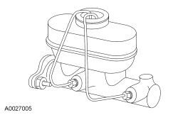
- Fill the brake master cylinder reservoir with clean, specified brake fluid.
- Have an assistant pump the brake pedal until clear fluid flows from the brake tubes without air bubbles.
- Remove the short brake tubes, and install the master cylinder brake tubes.
- Bleed the brake system. For additional information, refer to Brake System Bleeding in this section.
Brake Caliper
WARNING: Do not use any fluid other than clean brake fluid meeting manufacturer's specification. Additionally, do not use brake fluid that has been previously drained. Following these instructions will help prevent system contamination, brake component damage and the risk of serious personal injury.
WARNING: Carefully read cautionary information on product label. For emergency medical information seek medical advice. In the USA or Canada on Ford/Motorcraft products call: 1-800-959-3673. For additional information, consult the product Material Safety Data Sheet (MSDS) if available. Failure to follow these instructions may result in serious personal injury.
WARNING: Do not allow the brake master cylinder to run dry during the bleeding operation. Master cylinder may be damaged if operated without fluid, resulting in degraded braking performance. Failure to follow this instruction may result in serious personal injury.
NOTICE: Do not spill brake fluid on painted or plastic surfaces or damage to the surface may occur. If brake fluid is spilled onto a painted or plastic surface, immediately wash the surface with water.
- NOTE: It is not necessary to do a complete brake system bleed if
only the disc brake caliper was disconnected.
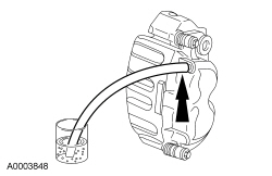
Remove the brake caliper bleeder screw cap and place a box-end wrench on the bleeder screw. Attach a rubber drain hose to the bleeder screw and submerge the free end of the hose in a container partially filled with clean, specified brake fluid.
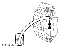
- Have an assistant pump the brake pedal and then hold firm pressure on the brake pedal.
- NOTE: Due to the complexity of the fluid path within the rear
integral parking brake calipers, it is necessary to press and release the
parking brake during the bleed procedure.
Loosen the bleeder screw until a stream of brake fluid comes out. While the assistant maintains pressure on the brake pedal, tighten the bleeder screw.
- If bleeding a rear brake caliper, press and release the parking brake 5 times.
- Repeat until clear, bubble-free fluid comes out.
- Refill the brake master cylinder reservoir as necessary.
- Tighten the brake caliper bleeder screw, remove the rubber hose and
install the bleeder screw cap.
- Tighten the front brake caliper bleeder screws to specification. For additional information, refer to Specifications in this section.
- Tighten the rear brake caliper bleeder screws to specification. For additional information, refer to Specifications in this section.
Brake System Bleeding
Special Tool(s)
Material
Pressure
WARNING: Do not use any fluid other than clean brake fluid meeting manufacturer's specification. Additionally, do not use brake fluid that has been previously drained. Following these instructions will help prevent system contamination, brake component damage and the risk of serious personal injury.
WARNING: Carefully read cautionary information on product label. For emergency medical information seek medical advice. In the USA or Canada on Ford/Motorcraft products call: 1-800-959-3673. For additional information, consult the product Material Safety Data Sheet (MSDS) if available. Failure to follow these instructions may result in serious personal injury.
WARNING: Do not allow the brake master cylinder to run dry during the bleeding operation. Master cylinder may be damaged if operated without fluid, resulting in degraded braking performance. Failure to follow this instruction may result in serious personal injury.
NOTICE: Do not spill brake fluid on painted or plastic surfaces or damage to the surface may occur. If brake fluid is spilled onto a painted or plastic surface, immediately wash the surface with water.
NOTE: Pressure bleeding the brake system is preferred to manual bleeding.
NOTE: The HCU bleeding procedure must be carried out if the HCU or any components upstream of the HCU are installed new.
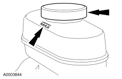
- Clean all the dirt from around the brake fluid reservoir cap and remove the cap. Fill the brake master cylinder reservoir with clean, specified brake fluid.
- NOTE: Master cylinder pressure bleeder adapter tools are
available from various manufacturers of pressure bleeding equipment. Follow
the instructions of the manufacturer when installing the adapter.
Install the bleeder adapter to the brake master cylinder reservoir and attach the bleeder tank hose to the fitting on the adapter.
- NOTE: Make sure the bleeder tank contains enough specified brake
fluid to complete the bleeding operation.
Open the valve on the bleeder tank.
- Apply 207-345 kPa (30-50 psi) to the brake system.
- Remove the RH rear bleeder cap and place a box-end wrench on the bleeder screw. Attach a rubber drain tube to the RH rear bleeder screw and submerge the free end of the tube in a container partially filled with clean, specified brake fluid.
- NOTE: Due to the complexity of the fluid path within the rear
integral parking brake calipers, it is necessary to press and release the
parking brake during the bleed procedure.
Loosen the RH rear bleeder screw. Leave open until clear, bubble-free brake fluid flows, then tighten the RH rear bleeder screw.
- Press and release the parking brake 5 times.
- Repeat until clear, bubble-free fluid comes out.
- Tighten the RH rear bleeder screw to specification. Refer to
Specifications in this section.
- Remove the rubber hose and install the bleeder screw cap.
- Repeat Steps 5 and 6 for the LH rear brake caliper.
- Continue bleeding the front of the system, going in order from the RH
front brake caliper and then to the LH front brake caliper.
- Tighten the front brake caliper bleeder screws to specification. Refer to Specifications in this section.
- Close the bleeder tank valve and release the pressure. Remove the tank hose from the adapter and remove the adapter. Fill the reservoir with clean, specified brake fluid and install the reservoir cap.
Manual
WARNING: Do not use any fluid other than clean brake fluid meeting manufacturer's specification. Additionally, do not use brake fluid that has been previously drained. Following these instructions will help prevent system contamination, brake component damage and the risk of serious personal injury.
WARNING: Carefully read cautionary information on product label. For emergency medical information seek medical advice. In the USA or Canada on Ford/Motorcraft products call: 1-800-959-3673. For additional information, consult the product Material Safety Data Sheet (MSDS) if available. Failure to follow these instructions may result in serious personal injury.
WARNING: Do not allow the brake master cylinder to run dry during the bleeding operation. Master cylinder may be damaged if operated without fluid, resulting in degraded braking performance. Failure to follow this instruction may result in serious personal injury.
NOTICE: Do not spill brake fluid on painted or plastic surfaces or damage to the surface may occur. If brake fluid is spilled onto a painted or plastic surface, immediately wash the surface with water.
NOTE: Pressure bleeding the brake system is preferred to manual bleeding.
NOTE: The HCU bleeding procedure must be carried out if the HCU or any components upstream of the HCU are installed new.
- Clean all the dirt from around the brake fluid reservoir cap and remove the cap. Fill the brake master cylinder reservoir with clean, specified brake fluid.

- Remove the RH rear bleeder cap and place a box-end wrench on the bleeder screw. Attach a rubber drain tube to the RH rear bleeder screw and submerge the free end of the tube in a container partially filled with clean, specified brake fluid.

- Have an assistant hold firm pressure on the brake pedal.
- NOTE: Due to the complexity of the fluid path within the rear
integral parking brake calipers, it is necessary to press and release the
parking brake during the bleed procedure.
Loosen the RH rear bleeder screw until a stream of brake fluid comes out. While the assistant maintains pressure on the brake pedal, tighten the RH rear bleeder screw.
- Press and release the parking brake 5 times.
- Repeat until clear, bubble-free fluid comes out.
- Refill the brake master cylinder reservoir as necessary.
- Tighten the RH rear bleeder screw to specification. Refer to
Specifications in this section.
- Remove the rubber hose and install the bleeder screw cap.
- Repeat Steps 2 through 5 for the LH rear brake caliper.
- Remove the RH front bleeder cap and place a box-end wrench on the bleeder screw. Attach a rubber drain tube to the RH front bleeder screw and submerge the free end of the tube in a container partially filled with clean, specified brake fluid.
- Have an assistant hold firm pressure on the brake pedal.
- Loosen the RH front bleeder screw until a stream of brake fluid comes
out. While the assistant maintains pressure on the brake pedal, tighten the
RH front bleeder screw.
- Repeat until clear, bubble-free fluid comes out.
- Refill the brake master cylinder reservoir as necessary.
- Tighten the RH front bleeder screw to specification. Refer to
Specifications in this section.
- Remove the rubber hose and install the bleeder screw cap.
- Repeat Steps 7 through 10 for the LH front brake caliper bleeder screw.
HCU Bleeding
NOTE: Pressure bleeding the brake system is preferred to manual bleeding.
- Follow the pressure bleeding or manual bleeding procedure steps to bleed the system.
- Connect the scan tool and follow the ABS Service Bleed instructions.
- Repeat the pressure bleeding or manual bleeding procedure steps to bleed the system.
 Brake System
...
 Front Disc Brake
SPECIFICATIONS
Torque Specifications
REMOVAL AND INSTALLATION
Brake Pads - 325 mm (13 in) Brakes
Material
Removal
WARNING:
Before beginning any service procedure in this section, refer to Safety Wa ...
Other materials:
Trailer towing
WARNING: Do not exceed the GVWR or the GAWR specified on
the certification label.
WARNING: Towing trailers beyond the maximum recommended
gross trailer weight exceeds the limit of your vehicle and could
result in engine damage, transmission damage, structural damage, loss
of vehicle control, ve ...
Transporting the vehicle
If you need to have your vehicle towed, contact a professional towing
service or, if you are a member of a roadside assistance program, your
roadside assistance service provider.
We recommend the use of a wheel lift and dollies or flatbed equipment
to tow your vehicle. Do not tow with a slin ...
Using sync with your media player
You can access and play music from your digital music player over the
vehicleŌĆÖs speaker system using the systemŌĆÖs media menu or voice
commands. You can also sort and play your music by specific categories,
such as artists, albums, etc.
SYNC is capable of hosting nearly any digital media pl ...
