SPECIFICATIONS
Torque Specifications
DESCRIPTION AND OPERATION
Anti-Lock Brake System (ABS) and Stability Control
Overview
The ABS and stability control system is comprised of the following subsystems which assist the driver in maintaining control of the vehicle:
- Base ABS
- EBD
- Traction control
- ESC
- Supplemental braking assist
- Supports Adaptive Cruise Control
- Supports Collision Avoidance
The base ABS helps to maintain steering control by preventing the wheels from locking up during hard braking. The base ABS also includes a brake assist function that will provide maximum brake system pressure during a severe braking situation.
The EBD system helps to maintain vehicle control by keeping a balanced braking condition between the front and rear wheels.
The traction control system helps to prevent loss of traction by reducing drive-wheel spin during acceleration.
The ESC system helps to prevent skids or lateral slides by activating portions of the base ABS.
The supplemental braking assist system uses the hydraulic pump motor and HCU to provide additional braking assist in the event of a severe vacuum loss at the brake booster, to maintain the distance gap set by the adaptive cruise control system or to aid in the avoidance of forward collisions.
For information on the Adaptive Cruise Control system, refer to Section 419-03B.
For information on the Collision Avoidance system, refer to Section 419-03C.
System Operation
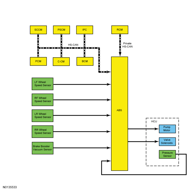
System Diagram
Network Message Chart
ABS Module Network Input Messages
Base ABS Function
The ABS module continuously monitors brake pedal input, lateral vehicle motion and the rotational speed of each wheel. The PCM sends the brake pedal switch information to the ABS module over the HS-CAN while the RCM sends lateral acceleration sensor information to the ABS module over a private HS-CAN. Wheel speed information is retrieved by the ABS module using 4 active wheel speed sensors, one for each wheel. When the ABS module detects an impending wheel lock during a braking event, the ABS module modulates brake pressure to the appropriate brake caliper(s) by opening and closing the appropriate solenoid valves inside the HCU while the hydraulic pump motor is activated. Once the affected wheel(s) return to the desired speed, the ABS module returns the solenoid valves in the HCU to their normal position.
The ABS module has 2 self-test options, one is carried out using a scan tool and the other is carried out when the ABS is initialized (ignition ON). During either self test the ABS module carries out a preliminary electrical check of the system sensors and activates the hydraulic pump motor for approximately one-half second. During this time, a buzzing or humming noise may be heard and a vibration may be felt in the brake pedal and is a normal condition. During the module initialized self test, the pump motor check is carried out at approximately 10 km/h (6.2 mph). Any malfunction detected in the system causes the module to set a DTC, disable the ABS function and send a message over the HS-CAN to the IPC to illuminate the ABS warning indicator. However, the base hydraulic power-assist braking system will function normally.
Electronic Brake Distribution (EBD)
On initial application of the brake pedal, full pressure is applied to the rear brakes. The ABS module then uses wheel speed sensor inputs to calculate an estimated rate of deceleration. Once vehicle deceleration exceeds a predetermined threshold, the ABS module commands the HCU to close the appropriate isolation valves to hold the rear brake pressure constant while allowing the front brake pressure to build. This creates a balanced braking condition between the front and rear wheels. As the vehicle decelerates, the valves are opened to increase the rear brake pressure in proportion to the front brake pressure. A slight bump sensation may be felt in the brake pedal when EBD is active. If the ABS is disabled due to DTCs being present in the ABS module, EBD continues to function unless the DTCs are for wheel speed sensors or the HCU /solenoid valves. When EBD is disabled, the ABS warning indicator, the red brake warning indicator and sliding car icon illuminate.
Traction Control
The ABS module continuously monitors and compares the rotational speed of the drive wheels in relation to the non-driven wheels. When the drive wheels begin to spin faster than the non-driven wheels, the ABS module modulates brake pressure to the appropriate brake caliper(s) by opening and closing the appropriate solenoid valves inside the HCU while the hydraulic pump motor is activated. At the same time, the ABS module calculates how much engine torque reduction is required to eliminate the wheel slip and sends this torque reduction message to the PCM over the HS-CAN. The ABS module also sends a traction event message to the IPC over the HS-CAN. When the PCM receives the torque reduction message, it adjusts engine timing and decreases fuel injector pulses to reduce the engine torque to the requested level. When the IPC receives traction event message, it flashes the sliding car icon.
Once the driven wheel speed returns to the desired speed, the ABS module returns the solenoid valves in the HCU to their normal position, deactivates the hydraulic pump motor and stops sending the traction event and torque reduction messages. The PCM returns engine timing and fuel injectors to normal operation and the IPC extinguishes the sliding car icon. After the vehicle speed exceeds 100 km/h (62.1 mph), traction control is accomplished only through the PCM torque control.
The traction control system can be disabled by the driver through the menu in the message center by changing the TRACTION CNTRL setting in the message center from ON to OFF. This is independent of the ABS and ESC functions, which cannot be disabled by the driver. When the driver disables the traction control function through the message center, the IPC communicates traction control system status to the ABS module over the HS-CAN and illuminates the sliding car OFF icon. The ABS module takes no further action in regards to traction control until the driver activates the function or until the ignition is cycled from OFF to ON.
The ABS module disables the traction control function if there are any wheel speed sensor or solenoid valve DTCs present in the ABS module. The traction control function is also disabled if there is a communication error between the ABS module and the PCM. When the traction control function is disabled, the ABS module sends a message to the IPC over the HS-CAN to illuminate the sliding car OFF icon.
Electronic Stability Control (ESC)
The ABS module continuously monitors the vehicle motion relative to the intended course. This is done by using sensors to compare the steering wheel input and the yaw rate sensor input with that of the actual vehicle motion. The SCCM (vehicles with active park assist) or PSCM (vehicles without active park assist) sends the steering wheel angle and rate of change information to the ABS module over the HS-CAN while the RCM sends yaw rate sensor information to the ABS module over a private HS-CAN. If the ABS module determines from the inputs that the vehicle is unable to travel in the intended direction, the ABS module modulates brake pressure to the appropriate brake caliper(s) by opening and closing the appropriate solenoid valves inside the HCU while the hydraulic pump motor is activated. At the same time, the ABS module calculates how much engine torque reduction is required to eliminate the wheel slip and sends this torque reduction message to the PCM over the HS-CAN. The ABS module also sends a traction event message to the IPC over the HS-CAN. When the PCM receives the torque reduction message, it adjusts engine timing and decreases fuel injector pulses to reduce the engine torque to the requested level. When the IPC receives traction event message, it flashes the sliding car icon.
Once the vehicle instability has been corrected, the ABS module returns the solenoid valves in the HCU to their normal position, deactivates the hydraulic pump motor and stops sending the traction event and torque reduction messages. The PCM returns engine timing and fuel injectors to normal operation and the IPC extinguishes the sliding car icon.
The ESC function does not operate with the transmission in REVERSE. The ABS module disables the ESC function if there are any wheel speed sensor, stability sensor or steering angle sensor DTCs present in the ABS module. Also, if there is a communication error between the ABS module and the PSCM, the SCCM or the RCM the ESC function is disabled. When the ESC function is disabled, the ABS module sends a message to the IPC over the HS-CAN to illuminate the sliding car icon.
MyKey Interaction
Through the MyKey feature, the traction control function of the stability control system can be configured to be always on or to allow the driver to select the traction control function on or off.
When the traction control function is configured to be always on and a MyKey restricted key is in use, the IPC will ignore any requests made by the driver to disable the traction control function and will not send any traction control disable messages to the ABS module. Refer to the Owner's Literature.
Stability/Traction Control Indicator (Sliding Car Icon)
Refer to Section 413-01.
Stability/Traction Control Disabled Indicator (Sliding Car OFF Icon)
Refer to Section 413-01.
Supplemental Braking Assist
The ABS module utilizes the HCU and hydraulic pump motor to aid in bringing the vehicle to a safe, controlled stop in the event of severe vacuum loss at the brake booster. The ABS module continually monitors the vacuum in the brake booster through the use of a vacuum sensor. When the vacuum sensor indicates vacuum is below a predetermined level, a DTC is set in the ABS module. The ABS module sends a message to the IPC over the HS-CAN to illuminate the red brake warning indicator. If a low vacuum condition occurs during a braking event or if the driver attempts to stop the vehicle with a low vacuum condition in the brake booster, the ABS module activates the hydraulic pump motor in the HCU to assist with vehicle braking.
On vehicles equipped with adaptive cruise control, the C-CM monitors the area forward of the vehicle. When an object enters this area and closes the distance gap set by the driver, the C-CM sends a deceleration request to the ABS module over the HS-CAN (either an adaptive cruise control deceleration request or a collision avoidance deceleration request). When the deceleration request message is received, the ABS module activates the hydraulic pump motor and solenoid valves in the HCU to slow the vehicle down to maintain the distance gap set by the driver. Once the distance gap set by the driver is achieved, the C-CM stops sending the deceleration request message and the ABS module deactivates the hydraulic pump motor and solenoid valves in the HCU. If the C-CM determines that the amount of braking provided by the ABS module is insufficient, the C-CM sends a forward collision avoidance braking request message to the ABS module and warns the driver, both audibly and visually, through the use of the HUD. After receiving the braking request message, the ABS module waits for brake pedal input and at that time applies maximum braking assist using the hydraulic pump motor and the HCU. For additional information on the adaptive cruise control system, refer to Section 419-03B. For additional information on the collision avoidance system, refer to Section 419-03C.
Component Description
ABS Module
The ABS module is attached directly to the HCU and is the ECU for all of the ABS and stability control systems. The module monitors all sensor inputs and all HS-CAN messages that relate to ABS and stability control and then directly controls the solenoid valves and the hydraulic pump motor.
The ABS module is available separately for service, however, the module is serviced with the HCU in the event that a new HCU is required. When a new ABS module is installed, whether with a new HCU or not, the module must be programmed with the vehicle information. For additional information on module programming, refer to Section 418-01.
Hydraulic Control Unit (HCU)
The HCU contains the solenoid valves, the hydraulic pump motor and the pressure sensor used by the ABS module for the ABS and stability control systems. The ABS module and the HCU are attached directly together. The ABS module is available separately for service, however, the module is serviced with the HCU in the event that a new HCU is required.
Wheel Speed Sensor
Both front wheel speed sensors are active (magneto resistive) sensors that operate on the Hall-effect principle to generate a square wave signal that is proportional to the rotational speed of the wheel. Because these are active sensors, receiving voltage from the ABS module and then sending a varying voltage back to the ABS module, they are able to detect much lower rotational speeds than passive (magnetic inductive) sensors. Each wheel speed sensor is connected to the ABS module by 2 circuits. One circuit provides voltage for sensor operation and the other circuit provides sensor input to the ABS module.
Both rear wheel speed sensors are active, bi-directional sensors. Each of the 2 sensors contain 2 sensing elements mounted side-by-side. Because the 2 sensing elements are mounted next to each other the 2 voltage signals are slightly out of phase, which causes one element to generate a voltage signal before the other element. This allows the ABS module to not only determine wheel speed, but also wheel direction for active park assist.
Wheel Speed Sensor Magnetic Strips
The wheel speed sensor magnetic strips are made up of many magnets arranged in a circle around one side of the wheel bearing in alternating poles, so as the bearing rotates the wheel speed sensor is exposed to alternating north-south magnetic fields. The magnetic strip is located on the side of the wheel bearing facing the vehicle and is part of the wheel bearing and, as such, is serviced with the bearing.
Stability Control Sensors
The stability control sensors for the vehicle dynamic system consist of the yaw rate sensor, lateral accelerometer and longitudinal accelerometer. The sensors are housed in the RCM which sends sensor information to the ABS module over a private HS-CAN. If any of the sensors are inoperative, a new RCM must be installed.
- The yaw rate sensor measures the yaw angle which is the difference between the direction the vehicle is pointing when cornering and the direction the vehicle is actually moving.
- The longitudinal accelerometer measures the acceleration and deceleration of the vehicle as it moves forward and backward.
- The lateral accelerometer measures the force created when a vehicle corners that tends to push a vehicle sideways.
Lateral acceleration has 2 forms. The first is the centrifugal acceleration that is generated when the vehicle travels around in a circle. The second is the acceleration due to gravity. On level ground there is no lateral acceleration due to gravity. However, if the vehicle is parked sideways on a bank or incline, the sensor measures some lateral acceleration due to gravity, even though the vehicle is not moving.
Steering Wheel Rotation Sensor
On vehicles not equipped with active park assist, the steering wheel rotation speed and direction of travel is determined by the PSCM and is sent to the ABS module over the HS-CAN.
On vehicles equipped with active park assist, the steering wheel rotation sensor directly measures the steering wheel rotation speed and direction of rotation. The sensor is mounted on the SCCM and the information is sent to the ABS module over the HS-CAN.
Brake Booster Vacuum Sensor
The brake booster vacuum sensor is a piezoelectric device used by the ABS module to monitor the vacuum in the brake booster. The sensor is hardwired to the ABS module by 3 circuits. One circuit is for the 5 volt sensor supply, one circuit is for sensor ground and one circuit is for sensor output. The sensor output ranges from 0.2 volt to 4.9 volts, depending on the amount of vacuum in the booster. The sensor is located on the front of the brake booster can be serviced separately from the brake booster.
DIAGNOSIS AND TESTING
Anti-Lock Brake System (ABS) and Stability Control
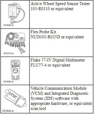
Special Tool(s)
DTC Chart
Diagnostics in this manual assume a certain skill level and knowledge of Ford-specific diagnostic practices. Refer to Diagnostic Methods in Section 100-00 for information about these practices.
ABS Module DTC Chart
Symptom Chart
Diagnostics in this manual assume a certain skill level and knowledge of Ford-specific diagnostic practices. Refer to Diagnostic Methods in Section 100-00 for information about these practices.
Diagnostic Routines
Pinpoint Test A: DTC U3003:16
Diagnostic Overview
Diagnostics in this manual assume a certain skill level and knowledge of Ford-specific diagnostic practices. Refer to Diagnostic Methods in Section 100-00 for information about these practices.
Refer to Wiring Diagrams Cell 42, Vehicle Dynamic Systems for schematic and connector information.
Normal Operation and Fault Conditions
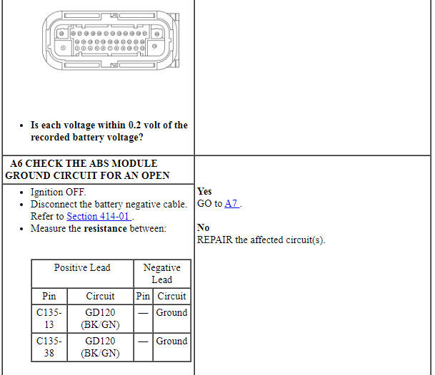
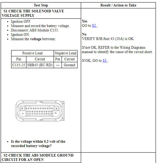
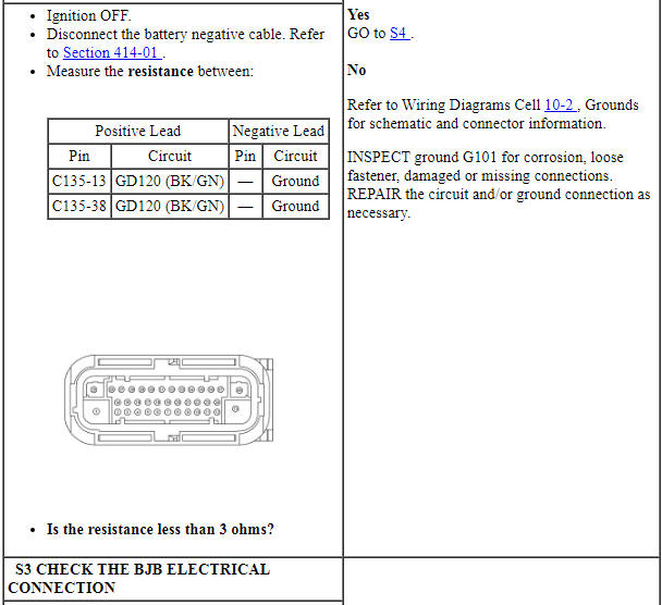
The ABS module, hydraulic pump and solenoid valves require an operating voltage that is between 10 and 17 volts. The ABS module receives this voltage from the BJB. The ABS module has a single ground circuit located in the engine compartment wiring harness. Excessive resistance or an open in one or more of these circuits, a discharged battery or a inoperative charging system will result in the ABS module setting a DTC.
DTC Fault Trigger Conditions
-
Possible Causes
- Wiring, terminals or connectors
- Charging system concern
- ABS module
Visual Inspection and Diagnostic Pre-checks
Make sure the vehicle battery terminals and cables are free of any corrosion and other contaminants.
Make sure the vehicle battery terminals are tightened to their correct torque specifications.
Make sure BJB fuses 5 (50A), 43 (20A) and 92 (10A) are OK.
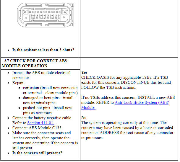
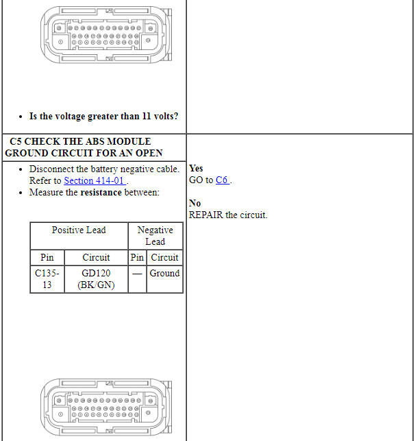
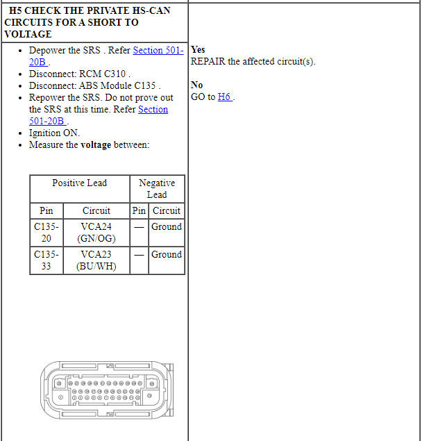
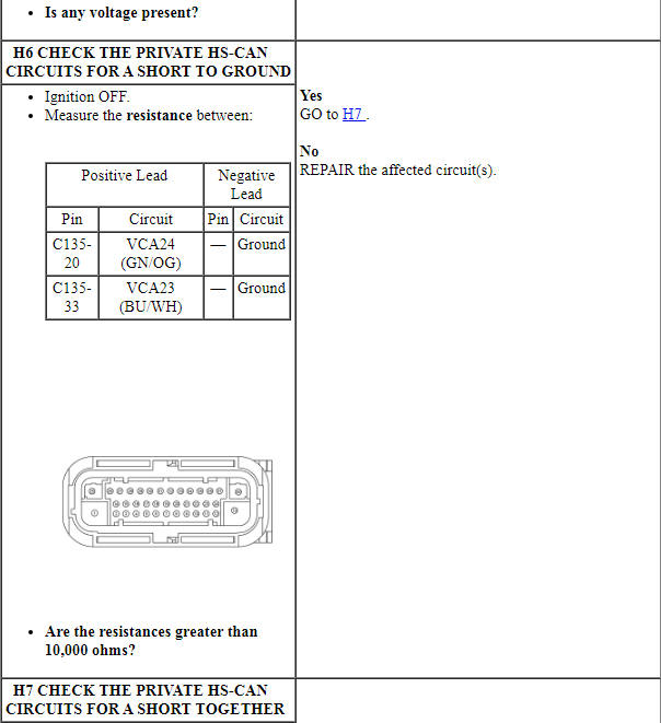
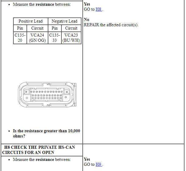
PINPOINT TEST A: DTC U3003:16
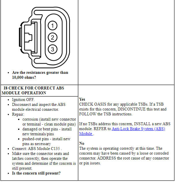
NOTICE: Use the correct probe adapter(s) when making measurements. Failure to use the correct probe adapter(s) may cause damage to the connector.
Pinpoint Test B: DTC U3003:17
Diagnostic Overview
Diagnostics in this manual assume a certain skill level and knowledge of Ford-specific diagnostic practices. Refer to Diagnostic Methods in Section 100-00 for information about these practices.
Refer to Wiring Diagrams Cell 42, Vehicle Dynamic Systems for schematic and connector information.
Normal Operation and Fault Conditions
The ABS module, hydraulic pump and solenoid valves require an operating voltage that is between 10 and 17 volts. The ABS module receives this voltage from the BJB. The ABS module has a single ground circuit located in the engine compartment wiring harness. An overcharging condition in the charging system will result in the ABS module setting a DTC. This DTC may also set in the ABS module due to battery charging or vehicle jump starting events.
DTC Fault Trigger Conditions
-
Possible Causes
- Charging system concern
- ABS module
PINPOINT TEST B: DTC U3003:17
Pinpoint Test C: DTCs C0020:16, 17 and 49
Diagnostic Overview
Diagnostics in this manual assume a certain skill level and knowledge of Ford-specific diagnostic practices. Refer to Diagnostic Methods in Section 100-00 for information about these practices.
Refer to Wiring Diagrams Cell 42, Vehicle Dynamic Systems for schematic and connector information.
Normal Operation and Fault Conditions
The ABS module uses an internal solid state switch to operate the hydraulic pump motor. The ABS module tests the hydraulic pump motor by activating it for 30 milliseconds. While the pump motor is being activated, the ABS module monitors the voltage drop across the hydraulic pump motor solid state switch and the amount of current the hydraulic pump motor draws through the solid state switch. If the voltage drop is too high or if the hydraulic pump motor is drawing too much current, the ABS module sets a DTC. After 30 milliseconds have passed, the ABS module stops applying voltage to the pump motor and observes the voltage that the spinning hydraulic pump motor is generating. The voltage generated by the motor indicates how fast the motor is spinning. Voltage that is too low indicates the motor is not spinning freely and a DTC sets.
DTC Fault Trigger Conditions
-
Possible Causes
- Fuse
- Wiring, terminals or connectors
- HCU
- ABS module
PINPOINT TEST C: C0020:16, 17 AND 49
NOTICE: Use the correct probe adapter(s) when making measurements. Failure to use the correct probe adapter(s) may cause damage to the connector.
Pinpoint Test D: Wheel Speed Sensor Erratic Signal DTCs
Diagnostic Overview
Diagnostics in this manual assume a certain skill level and knowledge of Ford-specific diagnostic practices. Refer to Diagnostic Methods in Section 100-00 for information about these practices.
Refer to Wiring Diagrams Cell 42, Vehicle Dynamic Systems for schematic and connector information.
Normal Operation and Fault Conditions
The wheel speed sensor utilizes the magnetic strip on the wheel bearing to generate a square wave signal proportional to wheel speed that is sent to the ABS module. The wheel bearing, magnetic strip and wheel speed sensor must be undamaged and free from any contamination to produce a clean signal for use by the ABS module. Also, all 4 tires and wheels must be of the same, manufacturer recommended size for the wheel speed sensor to generate an accurate wheel speed. Certain high frequency signals will interrupt the signals sent by the wheel speed sensors resulting in a temporary loss of the signal.
To clear any wheel speed sensor DTCs from the ABS module, after repairing the cause of the DTC, cycle the ignition from ON to OFF and back to ON. Then drive the vehicle for at least 1 minute at speeds above 20 km/h (12 mph).
DTC Fault Trigger Conditions
-
Possible Causes
- Incorrect/mismatched tires
- Wheel bearing
- Wheel speed sensor ring
- Wheel speed sensor
- Wiring, terminals or connectors
- ABS module
PINPOINT TEST D: WHEEL SPEED SENSOR ERRATIC SIGNAL DTCS
Pinpoint Test E: Wheel Speed Sensor Electrical Fault DTCs - Front
Diagnostic Overview
Diagnostics in this manual assume a certain skill level and knowledge of Ford-specific diagnostic practices. Refer to Diagnostic Methods in Section 100-00 for information about these practices.
Refer to Wiring Diagrams Cell 42, Vehicle Dynamic Systems for schematic and connector information.
Normal Operation and Fault Conditions
Refer to Wheel Speed Sensor in Description and Operation.
When the ignition is set to ON, the ABS module carries out a self-test by sending a reference voltage through the wheel speed sensors and their circuitry. An open circuit, a short to ground or a short to voltage in any wheel speed circuit causes the ABS module to disable the power output to that sensor(s) and set 1 or more DTCs.
To clear any wheel speed sensor DTCs from the ABS module, after repairing the cause of the DTC, cycle the ignition from ON to OFF and back to ON. Then drive the vehicle for at least 1 minute at speeds above 20 km/h (12 mph).
DTC Fault Trigger Conditions
-
Possible Causes
- Wiring, terminals or connectors
- Wheel speed sensor
- ABS module
Visual Inspection and Diagnostic Pre-checks
Make sure the wheel speed sensor harness is routed correctly and is undamaged.
Make sure the wheel speed sensor electrical connector is free from any corrosion or other contaminants.
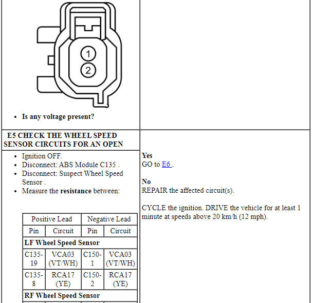
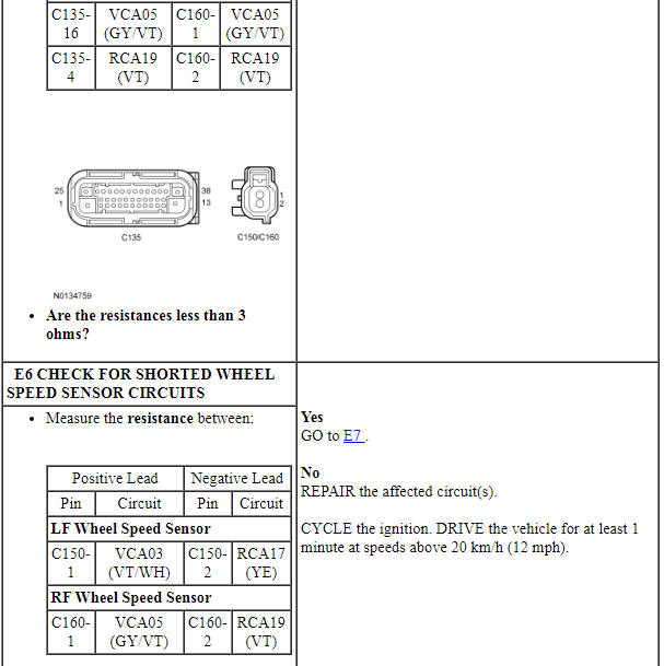
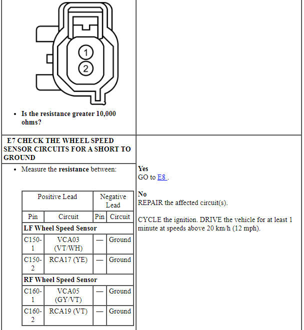
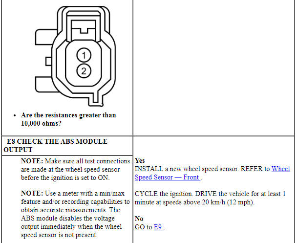
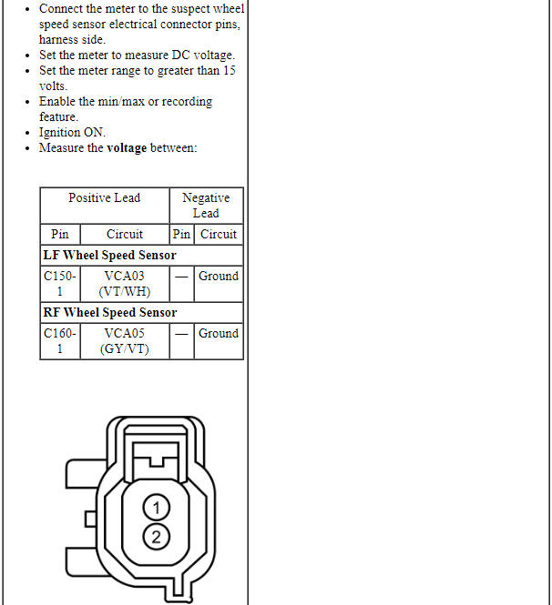
PINPOINT TEST E: WHEEL SPEED SENSOR ELECTRICAL FAULT DTCs - FRONT
NOTICE: Use the correct probe adapter(s) when making measurements. Failure to use the correct probe adapter(s) may cause damage to the connector.
Pinpoint Test F: Wheel Speed Sensor Electrical Fault DTCs - Rear
Diagnostic Overview
Diagnostics in this manual assume a certain skill level and knowledge of Ford-specific diagnostic practices. Refer to Diagnostic Methods in Section 100-00 for information about these practices.
Refer to Wiring Diagrams Cell 42, Vehicle Dynamic Systems for schematic and connector information.
Normal Operation and Fault Conditions
Refer to Wheel Speed Sensor in Description and Operation.
When the ignition is set to ON, the ABS module carries out a self-test by sending a reference voltage through the wheel speed sensors and their circuitry. An open circuit, a short to ground or a short to voltage in any wheel speed circuit causes the ABS module to disable the power output to that sensor(s) and set 1 or more DTCs.
To clear any wheel speed sensor DTCs from the ABS module, after repairing the cause of the DTC, cycle the ignition from ON to OFF and back to ON. Then drive the vehicle for at least 1 minute at speeds above 20 km/h (12 mph).
DTC Fault Trigger Conditions
-
Possible Causes
- Wiring, terminals or connectors
- Wheel speed sensor
- ABS module
Visual Inspection and Diagnostic Pre-checks
Make sure the wheel speed sensor harness is routed correctly and is undamaged.
Make sure the wheel speed sensor electrical connector is free from any corrosion or other contaminants.
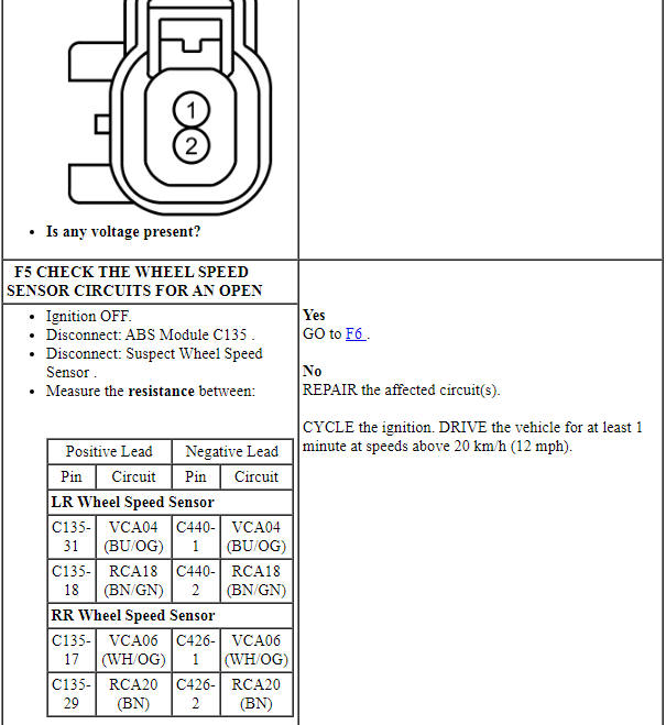
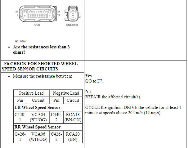
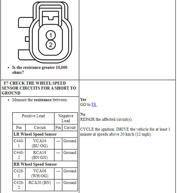
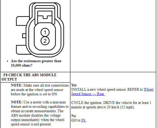
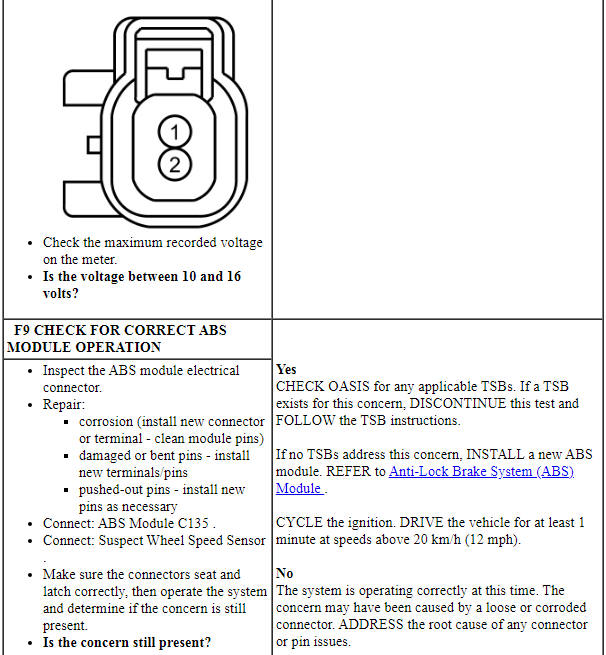
PINPOINT TEST F: WHEEL SPEED SENSOR ELECTRICAL FAULT DTCs - REAR
NOTICE: Use the correct probe adapter(s) when making measurements. Failure to use the correct probe adapter(s) may cause damage to the connector.

Pinpoint Test G: DTC C0040:64
Diagnostic Overview
Diagnostics in this manual assume a certain skill level and knowledge of Ford-specific diagnostic practices. Refer to Diagnostic Methods in Section 100-00 for information about these practices.
Refer to Wiring Diagrams Cell 42, Vehicle Dynamic Systems for schematic and connector information.
Normal Operation and Fault Conditions
The ABS module receives brake pedal switch input from the PCM over the HS-CAN. The ABS module compares this information against the pressure sensor in the HCU to determine if the brake pedal input is valid. A brake pedal switch that is incorrectly installed can cause a signal plausibility concern.
This DTC cannot be cleared using a scan tool. To clear this DTC, the root cause must first be identified and repaired. Then the ABS module must receive a valid brake pedal input from the PCM. This is accomplished by setting the ignition to ON and pressing and releasing the brake pedal at least twice.
DTC Fault Trigger Conditions
-
Possible Causes
- Stoplamp switch
- Vehicle communication bus
- ABS module
Visual Inspection and Diagnostic Pre-checks
Make sure the stoplamp switch electrical connector is connected and free of corrosion and other contaminants.
Make sure the stoplamp switch is installed correctly.
Make sure the stoplamp switch is operating correctly.
PINPOINT TEST G: DTC C0040:64
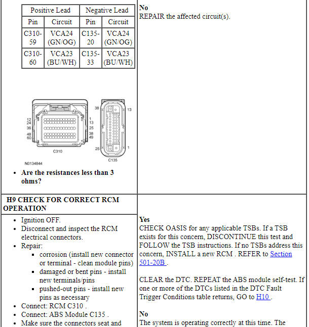
Pinpoint Test H: Stability Control Sensor Signal Failure DTCs
Diagnostic Overview
Diagnostics in this manual assume a certain skill level and knowledge of Ford-specific diagnostic practices. Refer to Diagnostic Methods in Section 100-00 for information about these practices.
Refer to Wiring Diagrams Cell 42, Vehicle Dynamic Systems for schematic and connector information.
Normal Operation and Fault Conditions
The RCM measures vehicle yaw rate, lateral acceleration and longitudinal acceleration, then sends the information to the ABS module over a private HS-CAN. This private HS-CAN is used only for communication between the RCM and the ABS module. The yaw rate sensor, lateral and longitudinal accelerometers are contained in the RCM.
A circuit fault such as a short or an open disrupts communication between the modules and the ABS module sets a DTC. An incorrectly installed RCM sends invalid information to the ABS module, which sets a DTC.
DTC Fault Trigger Conditions
-
Possible Causes
- Wiring, terminals or connectors
- RCM
- ABS module
PINPOINT TEST H: STABILITY CONTROL SENSOR SIGNAL FAILURE DTCS
NOTICE: Use the correct probe adapter(s) when making measurements. Failure to use the correct probe adapter(s) may cause damage to the connector.
Pinpoint Test I: DTCs C101A:15, C101A:16 and C101A:29
Diagnostic Overview
Diagnostics in this manual assume a certain skill level and knowledge of Ford-specific diagnostic practices. Refer to Diagnostic Methods in Section 100-00 for information about these practices.
Refer to Wiring Diagrams Cell 42, Vehicle Dynamic Systems for schematic and connector information.
Normal Operation and Fault Conditions
The brake booster vacuum pressure sensor receives a sensor supply voltage of 5 volts from the ABS module. The sensor is also grounded through the ABS module. The sensor uses the pressure differential between the atmosphere and the brake booster vacuum chamber to produce a return voltage signal to the ABS module that is between 0.2 volt and 4.9 volts. The ABS module uses other sensor inputs such as wheel speed, brake pedal and stability sensors to determine if the vehicle is stopping and at what rate of deceleration. This information is compared against the vacuum pressure sensor to determine the validity of the sensor signal and the working condition of the sensor itself. A vacuum leak, a circuit failure in the sensor wiring, a brake booster with a mechanical failure or an internal failure of the vacuum sensor or ABS module results in a DTC being set in the ABS module.
DTC Fault Trigger Conditions
-
Possible Causes
- Vacuum leak
- Vacuum hoses
- Wiring, terminals or connectors
- Vacuum sensor
- Brake booster
- ABS module
Visual Inspection and Diagnostic Pre-checks
Inspect the brake booster for vacuum leaks.
Inspect the brake booster for any obvious signs of damage.
Inspect the brake booster vacuum sensor harness and connector of any obvious signs of damage.
Make sure the brake booster vacuum sensor electrical connector is free from any corrosion or other contaminants.
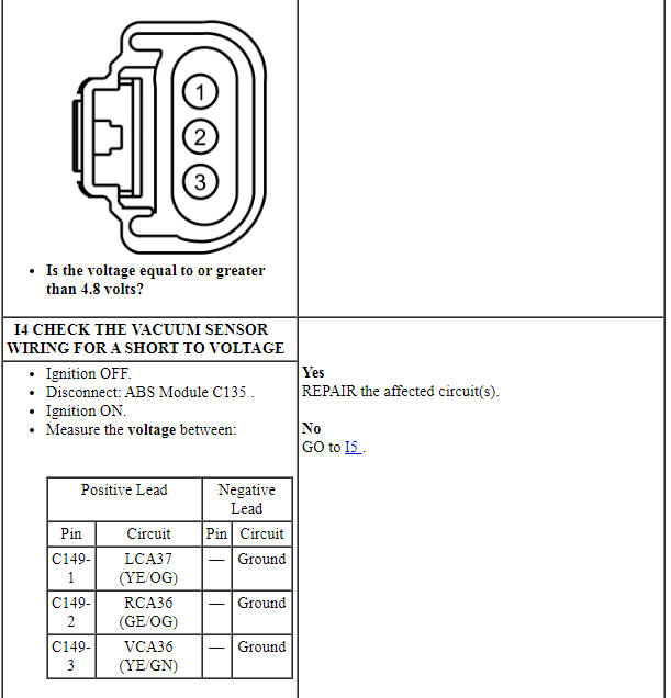
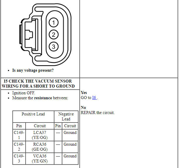
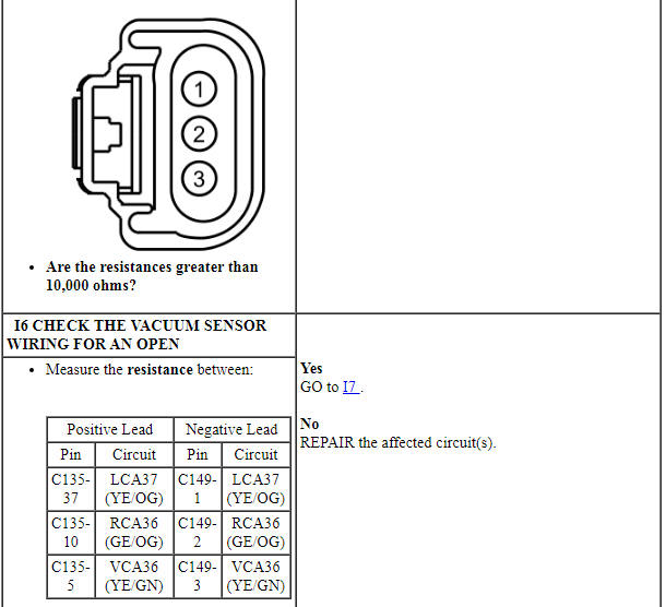
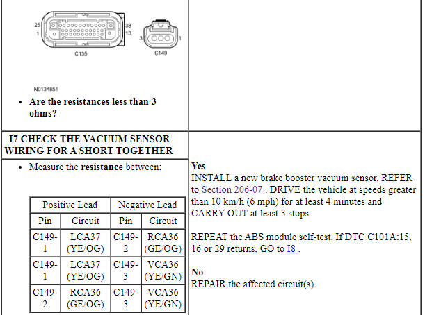
PINPOINT TEST I: DTCS C101A:15, C101A:16 AND C101A:29
NOTICE: Use the correct probe adapter(s) when making measurements. Failure to use the correct probe adapter(s) may cause damage to the connector.
Pinpoint Test J: DTC U0100:00
Diagnostic Overview
Diagnostics in this manual assume a certain skill level and knowledge of Ford-specific diagnostic practices. Refer to Diagnostic Methods in Section 100-00 for information about these practices.
Refer to Wiring Diagrams Cell 42, Vehicle Dynamic Systems for schematic and connector information.
Normal Operation and Fault Conditions
With the ignition ON, the PCM sends messages to the ABS module over the HS-CAN. If the ABS module does not receive these messages within a certain time frame (less than 1 second), the ABS module sets DTCs. For information on the messages sent to the ABS module by the PCM, refer to the Network Message Chart.
DTC Fault Trigger Conditions
-
Possible Causes
- Vehicle communication bus
- PCM
- ABS module
PINPOINT TEST J: DTC U0100:00
Pinpoint Test K: DTC U0104:00
Diagnostic Overview
Diagnostics in this manual assume a certain skill level and knowledge of Ford-specific diagnostic practices. Refer to Diagnostic Methods in Section 100-00 for information about these practices.
Refer to Wiring Diagrams Cell 42, Vehicle Dynamic Systems for schematic and connector information.
Normal Operation and Fault Conditions
With the ignition ON, the C-CM sends the ABS module messages over the HS-CAN. If the ABS module does not receive these messages within a certain time frame (less than 1 second), the ABS module sets DTCs. For information on the messages sent to the ABS module from the C-CM, refer to the Network Message Chart.
DTC Fault Trigger Conditions
-
Possible Causes
- Vehicle communication bus
- C-CM
- ABS module
PINPOINT TEST K: DTC U0104:00
Pinpoint Test L: DTC U0131:00
Diagnostic Overview
Diagnostics in this manual assume a certain skill level and knowledge of Ford-specific diagnostic practices. Refer to Diagnostic Methods in Section 100-00 for information about these practices.
Refer to Wiring Diagrams Cell 42, Vehicle Dynamic Systems for schematic and connector information.
Normal Operation and Fault Conditions
On vehicles not equipped with active park assist, with the ignition ON, the PSCM sends messages to the ABS module over the HS-CAN.
On vehicles equipped with active park assist, with the ignition ON, the SCCM sends messages to the ABS module over the HS-CAN.
If the ABS module does not receive these messages within a certain time frame (less than 1 second), the ABS module sets DTCs. For information on the messages sent to the ABS module from the PSCM and SCCM, refer to the Network Message Chart.
DTC Fault Trigger Conditions
-
Possible Causes
- Vehicle communication bus
- PSCM (vehicles without active park assist)
- SCCM (vehicles with active park assist)
- ABS module
PINPOINT TEST L: DTC U0131:00
Pinpoint Test M: DTC U0140:00
Diagnostic Overview
Diagnostics in this manual assume a certain skill level and knowledge of Ford-specific diagnostic practices. Refer to Diagnostic Methods in Section 100-00 for information about these practices.
Refer to Wiring Diagrams Cell 42, Vehicle Dynamic Systems for schematic and connector information.
Normal Operation and Fault Conditions
With the ignition ON, the BCM sends the ABS module messages over the HS-CAN. If the ABS module does not receive these messages within a certain time frame (less than 1 second), the ABS module sets DTCs. For information on the messages sent to the ABS module by the BCM, refer to the Network Message Chart.
DTC Fault Trigger Conditions
-
Possible Causes
- Vehicle communication bus
- BCM
- ABS module
PINPOINT TEST M: DTC U0140:00
Pinpoint Test N: DTC U0151:00
Diagnostic Overview
Diagnostics in this manual assume a certain skill level and knowledge of Ford-specific diagnostic practices. Refer to Diagnostic Methods in Section 100-00 for information about these practices.
Refer to Wiring Diagrams Cell 42, Vehicle Dynamic Systems for schematic and connector information.
Normal Operation and Fault Conditions
With the ignition ON, the RCM sends the ABS module messages over a private HS-CAN. If the ABS module does not receive these messages within a certain time frame (less than 1 second), the ABS module sets DTCs.
DTC Fault Trigger Conditions
-
Possible Causes
- Vehicle communication bus
- RCM
- ABS module
PINPOINT TEST N: DTC U0151:00
Pinpoint Test O: DTC U0155:00
Diagnostic Overview
Diagnostics in this manual assume a certain skill level and knowledge of Ford-specific diagnostic practices. Refer to Diagnostic Methods in Section 100-00 for information about these practices.
Refer to Wiring Diagrams Cell 42, Vehicle Dynamic Systems for schematic and connector information.
Normal Operation and Fault Conditions
With the ignition ON, the IPC sends the ABS module messages over the HS-CAN. If the ABS module does not receive these messages within a certain time frame (less than 1 second), the ABS module sets DTCs.
DTC Fault Trigger Conditions
-
Possible Causes
- Vehicle communication bus
- IPC
- ABS module
PINPOINT TEST O: DTC U0155:00

Pinpoint Test P: DTC U3002:62
Diagnostic Overview
Diagnostics in this manual assume a certain skill level and knowledge of Ford-specific diagnostic practices. Refer to Diagnostic Methods in Section 100-00 for information about these practices.
Refer to Wiring Diagrams Cell 42, Vehicle Dynamic Systems for schematic and connector information.
Normal Operation and Fault Conditions
Diagnose any network communication DTCs prior to diagnosing U3002:62.
With the ignition ON, the ABS module and the PCM share the VIN information over the HS-CAN. If the ABS module does not receive these messages within a certain time frame (less than 1 second), the ABS module sets DTCs.
DTC Fault Trigger Conditions
-
Possible Causes
- Module configuration (ABS and PCM)
- ABS module
PINPOINT TEST P: DTC U3002:62
Pinpoint Test Q: The Stability/Traction Control System is Inoperative or Cannot Be Disabled
Diagnostic Overview
Diagnostics in this manual assume a certain skill level and knowledge of Ford-specific diagnostic practices. Refer to Diagnostic Methods in Section 100-00 for information about these practices.
Refer to Wiring Diagrams Cell 60, Instrument Cluster for schematic and connector information.
Normal Operation and Fault Conditions
Traction control system status is relayed to the driver by the sliding car OFF icon in the IPC. When the driver deactivates the traction control, the IPC sends a message to the ABS module over the HS-CAN. The ABS module deactivates the traction control system and sends a message back to the IPC to illuminate the sliding car OFF icon. The traction control system remains deactivated until the driver changes the traction control state in the message center or until the ignition is cycled.
-
Possible Causes
- Vehicle communication bus
- IPC
PINPOINT TEST Q: THE STABILITY/TRACTION CONTROL SYSTEM IS INOPERATIVE OR CANNOT BE DISABLED
Pinpoint Test R: DTCs C0051:23, 27, 29, 54 and 64
Diagnostic Overview
Diagnostics in this manual assume a certain skill level and knowledge of Ford-specific diagnostic practices. Refer to Diagnostic Methods in Section 100-00 for information about these practices.
Normal Operation and Fault Conditions
The ABS module uses the steering wheel position sensor in conjunction with the RCM sensor information to determine vehicle direction of travel. For vehicles not equipped with active park assist, the ABS module receives the steering wheel position information from the PSCM over the HS-CAN. For vehicles equipped with active park assist, the ABS module receives the steering wheel position information from the SCCM over the HS-CAN.
The ABS module continually compares the steering wheel position information received against other sensor information to determine the validity of the information received. An internal failure of the steering wheel position sensor, RCM, PSCM, SCCM or a vehicle communication concern causes the ABS module to set 1 or more DTCs.
DTC Fault Trigger Conditions
-
Possible Causes
- Vehicle communication bus
- Steering wheel rotation sensor
- RCM
- PSCM (part of steering gear assembly)
PINPOINT TEST R: DTCs C0051:23, 27, 29, 54 AND 64
Pinpoint Test S: DTC C1A77:11
Diagnostic Overview
Diagnostics in this manual assume a certain skill level and knowledge of Ford-specific diagnostic practices. Refer to Diagnostic Methods in Section 100-00 for information about these practices.
Refer to Wiring Diagrams Cell 42, Vehicle Dynamic Systems for schematic and connector information.
Normal Operation and Fault Conditions
The solenoid valves in the HCU require an operating voltage that is between 10 and 17 volts. The HCU receives this voltage from the ABS module and the ABS module receives this voltage from the BJB. The ABS module has 2 ground circuits located in the left-hand side of the engine compartment near the BJB. Excessive resistance or an open in one or more of these circuits, a discharged battery or a inoperative charging system result in the ABS module setting a DTC.
DTC Fault Trigger Conditions
-
Possible Sources
- Fuse
- Wiring, terminals or connectors
- ABS module
PINPOINT TEST S: DTC C1A77:11
REMOVAL AND INSTALLATION
Hydraulic Control Unit (HCU)
Special Tool(s)
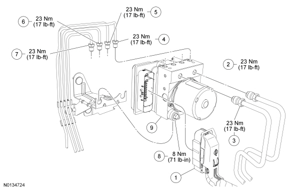
Removal and Installation
NOTICE: Do not spill brake fluid on painted or plastic surfaces or damage to the surface may occur. If brake fluid is spilled onto a painted or plastic surface, immediately wash the surface with water.
NOTICE: Electronic modules are sensitive to electrical charges. The Anti-lock Brake System (ABS) module can be damaged if exposed to these charges.
- NOTE: This step is only necessary if a new ABS module or a new
Hydraulic Control Unit (HCU) is being installed.
Connect the scan tool and upload the module configuration information from the ABS module. For additional information, refer to Section 418-01.
- With the vehicle in NEUTRAL, position it on a hoist. For additional information, refer to Section 100-02.
- Remove the battery tray. For additional information, refer to Section 414-01.
- Disconnect the ABS electrical connector.
- NOTE: Brake tubes must be installed in their original locations
and orientations.
Loosen the brake tube-to- HCU fittings and position the brake tubes aside.
- To install, tighten to 23 Nm (17 lb-ft).
- Loosen the 2 bracket-to- HCU nuts and remove the HCU.
- To install, tighten to 8 Nm (71 lb-in).
- To install, reverse the removal procedure.
- If a new ABS module or HCU was installed, connect the scan tool and download the module configuration information from the scan tool. For additional information, refer to Section 418-01.
- Bleed the brake system. For additional information, refer to Section 206-00.
Anti-Lock Brake System (ABS) Module
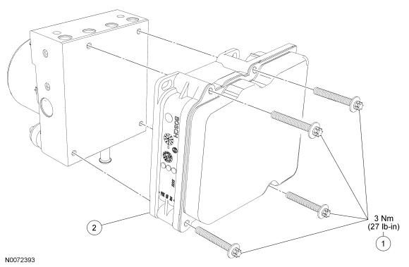
Removal and Installation
NOTICE: Electronic modules are sensitive to electrical charges. The Anti-lock Brake System (ABS) module can be damaged if exposed to these charges.
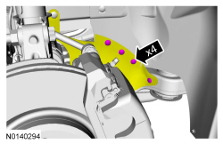
- Remove the Hydraulic Control Unit (HCU). For additional information, refer to Hydraulic Control Unit (HCU) in this section.
- Remove and discard the 4 screws.
- To install, tighten the new screws to 3 Nm (27 lb-in).
- Remove the ABS module.
- To install, reverse the removal procedure.
Wheel Speed Sensor - Front
Removal
NOTE: Steps in the removal procedure may contain installation details.
- Remove the wheel and tire. Refer to Section 204-04.
-
- To install, tighten to 15 Nm (133 lb-in).
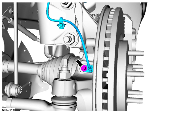
Installation
- To install, reverse the removal procedure.
Wheel Speed Sensor - Rear
NOTE: LH side shown, RH side similar.
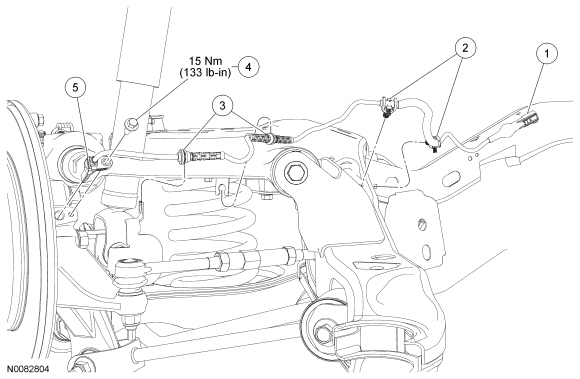
Removal and Installation
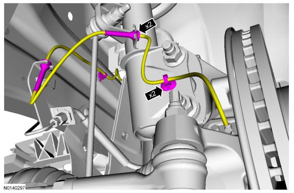
- NOTICE: Make sure to correctly route and secure the wheel
speed sensor harness in the rear subframe assembly or damage to the harness
may occur.
With the vehicle in NEUTRAL, position it on a hoist. For additional information, refer to Section 100-02.
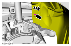
- Disconnect the wheel speed sensor electrical connector.
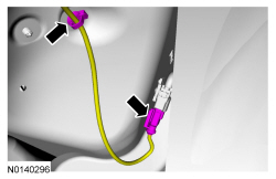
- Detach the 2 wheel speed sensor pin-type retainers.
- Detach the 2 wheel speed sensor harness retainers.
- Remove the wheel speed sensor bolt.
- To install, tighten to 15 Nm (133 lb-in).
- Remove the wheel speed sensor.
- To install, reverse the removal procedure.
Stability/Traction Control Switch
Removal and Installation
- For additional information, refer to Passenger Air Bag Deactivation (PAD) in Section 501-20B.
Steering Wheel Rotation Sensor
Removal
- NOTE: The steering wheel rotation sensor may be attached to the
clockspring when the clockspring is removed.
Remove the clockspring. For additional information, refer to Section 501-20B.
- Remove the steering wheel rotation sensor.
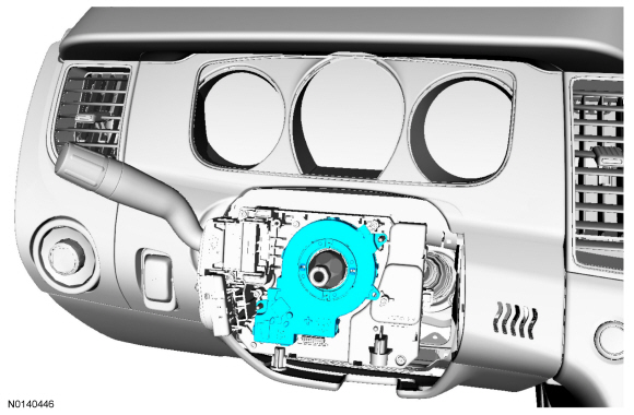
Installation
- To install, reverse the removal procedure.
 Power Brake Actuation
SPECIFICATIONS
Torque Specifications
DESCRIPTION AND OPERATION
Brake Booster
The power brake actuation system includes a vacuum sorce (engine manifold or
vacuum pump), vacuum assisted brake booster, ...
 Steering System
DESCRIPTION AND OPERATION
Steering System
Electronic Power Assist Steering (EPAS) System
The Electronic Power Assist Steering (EPAS) system consists of the following
components:
Power Steering Cont ...
Other materials:
Specifications, Description and Operation
SPECIFICATIONS
Torque Specifications
DESCRIPTION AND OPERATION
Safety Belt System
WARNING: All
safety belt components must be inspected and corrected as part of any collision
repair. Inspect all safety belt components as prescribed by Safety Belt
Inspection and Repair After a Collision fou ...
Front End Body Panels
SPECIFICATIONS
Torque Specifications
DESCRIPTION AND OPERATION
Active Grille Shutter System
Overview
The grille shutter system (when equipped) is comprised of the grille shutter
assembly and the grille shutter actuator. The grille shutter system is primarily
used to maximize fuel economy by reduc ...
Specifications, Description and Operation
SPECIFICATIONS
Torque Specifications
DESCRIPTION AND OPERATION
Rear View Mirrors
Exterior, Power
Overview
Power mirrors allow the LH and RH exterior mirror glass to be positioned
electronically. The position of the power mirror glass is controlled by the
exterior mirror control switch. Selecting ...
