DESCRIPTION AND OPERATION
Steering System
Electronic Power Assist Steering (EPAS) System
The Electronic Power Assist Steering (EPAS) system consists of the following components:
- Power Steering Control Module (PSCM) - the PSCM controls the functions of the EPAS system and communicates with other modules that are on the High Speed Controller Area Network (HS-CAN) bus. The PSCM is attached to the RH side of the EPAS gear assembly and is not available separately for service.
- Motor - the EPAS gear uses a 12-volt reversible motor to control the steering effort. The motor is connected to the steering rack by a toothed belt and a pulley/bearing assembly. The motor is used by the PSCM to move the rack inside the gear housing. Motor position is used to determine steering wheel angle/position instead of using a separate sensor. The motor is attached to the RH side of the EPAS gear assembly and is not available separately for service.
- Steering shaft torque sensor - the steering shaft torque sensor is used by the PSCM to determine how much force the steering wheel is being turned. The sensor sends out 2 signals, one for left and one for right. When the steering wheel is turned to the left, the left signal increases while the right signal decreases, likewise when the steering wheel is turned to the right, the right signal increases while the left signal decreases. This allows the PSCM to determine if the driver intends to go left or right in order to spin the motor in the appropriate direction. The sensor is mounted near the input shaft of the EPAS gear assembly and is not available separately for service.
- Inner tie rod - one inner tie rod is located at each end of the EPAS gear assembly and is available separately for service. Refer to Section 211-02.
- Outer tie rod - one outer tie rod is located at each end of the EPAS gear assembly and is available separately for service. Refer to Section 211-02.
- EPAS gear bellows boot - one bellows boot is located on each side of the EPAS gear assembly. Each boot is held in place with 2 boot clamps. The boots and clamps are available for service, refer to Section 211-02.
The EPAS system utilizes a rack-and-pinion type steering gear. Power assist is provided by a motor that is connected to the steering rack by a belt and a pulley and bearing assembly. The steering gear and motor/module are serviced as an assembly. A new steering gear includes inner tie rods, however, the inner and outer tie rods can also be serviced separately. For information on tie-rod end service, refer to Section 211-02.
Active Park Assist
Some vehicles equipped with EPAS may also be equipped with active park assist. The active park assist system is controlled by the Parking Aid Module (PAM) and, when activated, can detect a parking space and steer the vehicle into the space by sending commands to the EPAS gear (the driver still controls the throttle, brakes and transmission). The active park assist system is comprised of several systems/modules that work together to aid in parallel parking maneuvers, the presence of certain DTCs in any of those systems/modules may either keep the active park assist system from being enabled or may disable the system if currently being used. Refer to Section 413-13C for detailed information on active park assist.
DIAGNOSIS AND TESTING
Steering System
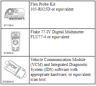
Special Tool(s)
Principles of Operation
Electronic Power Assist Steering (EPAS) System
The Electronic Power Assist Steering (EPAS) system provides power steering assist to the driver by replacing the conventional hydraulic valve system with an electric motor coupled to the steering rack by a toothed belt. The motor is controlled by the Power Steering Control Module (PSCM) that senses steering effort/use through the use of a torque sensor which is mounted near the input shaft of the steering gear. Steering assist is provided in proportion to the steering input effort and vehicle speed.
The EPAS system requires a 12-volt, hot at all times feed for system operation. The PSCM is activated when power is applied to the hard-wired ignition/run input. After activation, the PSCM monitors the High Speed Controller Area Network (HS-CAN) bus to determine if the vehicle is operating in a manner capable of supporting the EPAS system.
Once this is determined, vehicle speed sent by the PCM over the HS-CAN bus, steering shaft speed and direction sent by the torque sensor and steering wheel angle/position determined by the motor position all provide the necessary information for the PSCM to determine the amount or level of assist provided by the EPAS system.
Assist is primarily based off of vehicle speed. As vehicle speed increases, the amount of assist provided by the system is decreased to improve and enhance road feel at the steering wheel. As vehicle speed decreases, the amount of assist provided by the system is increased to ease vehicle maneuvering. If the vehicle speed is missing or out of range, the PSCM defaults to a safe level of assist for all driving conditions. If the vehicle speed returns to the correct in-range values, the PSCM will adjust the level of assist accordingly. Steering wheel/shaft speed, torque and direction information will allow the PSCM to determine how much assist is needed to turn the wheels right and left.
The PSCM is self-monitoring and has the capability of setting and storing DTCs. Depending on the DTC set, the control module will enter into a "safe mode" of manual steering. In addition, the PSCM may send a request to the Instrument Panel Cluster (IPC) module over the HS-CAN bus to display a message in the message center to alert the driver of a potential EPAS concern.
Active Park Assist
When the active park assist system is enabled, the Parking Aid Module (PAM) will utilize ultrasonic sensors to locate and measure a parking space. Once a parking space is identified by the system and chosen by the driver, the PAM will then send steering command messages to the PSCM over the HS-CAN bus. The PSCM will utilize steering angle information transmitted by the Steering Angle Sensor Module (SASM) over the HS-CAN bus and wheel speed information transmitted by the ABS module over the HS-CAN bus to actuate the steering system as requested by the PAM.
Any driver inputs via the steering wheel will deactivate the active park assist system. Also, the presence of certain DTCs in the PSCM and/or ABS module will disable the system or keep the system from being activated. Refer to Section 413-13C for information on the active park assist system.
Interactive Diagnostics
For diagnosing and testing please refer to the on-line Workshop Manual. If you do not have an on-line subscription, go to www.motorcraftservice.com.
 Anti-Lock Brake System (ABS) and Stability Control
SPECIFICATIONS
Torque Specifications
DESCRIPTION AND OPERATION
Anti-Lock Brake System (ABS) and Stability Control
Overview
The ABS and stability control system is comprised of the following subsystem ...
 Power Steering
SPECIFICATIONS
Torque Specifications
a Refer to the procedure for the specification.
REMOVAL AND INSTALLATION
Steering Gear
Special Tool(s)
NOTE: 3.5L GTDI engine shown, 3.5L&nbs ...
Other materials:
Changing a fuse
Fuses
WARNING: Always replace a fuse with one that has the
specified amperage rating. Using a fuse with a higher amperage
rating can cause severe wire damage and could start a fire.
If electrical components in your
vehicle are not working, a fuse may
have blown. Blown fuses are
identified b ...
General Procedures
Audio Control Module (ACM) Self-Diagnostic Mode
NOTE: If the ACM is completely inoperative (does not power up), the
part number decal on the ACM chassis can be used to attain the ACM part number.
Turn the ACM on.
Operate the audio system in radio tu ...
Specifications, Description and Operation
SPECIFICATIONS
Material
a 6F50 transmission.
b 6F55 transmission.
Torque Specifications
a Refer to the procedure in this section.
General Specifications
Solenoid Operation Chart
a Turns on
above 8 km/h (5 mph).
b Turns off above 8 km/h (5 mph).
NC = Normally closed
NH = ...
