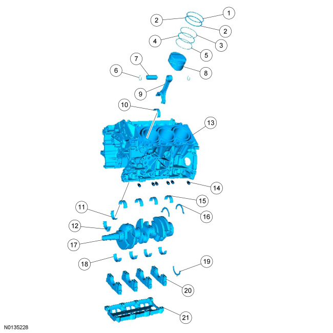
Engine
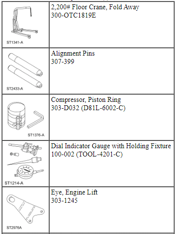
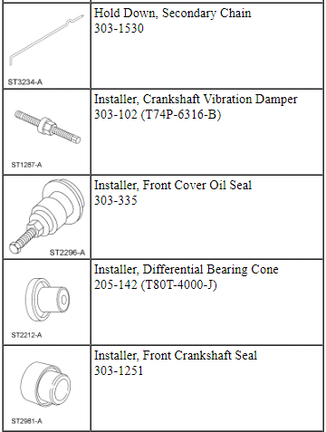
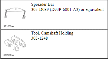
Special Tool(s)
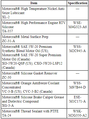
Material
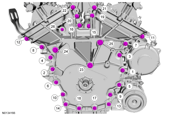
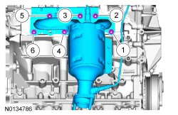
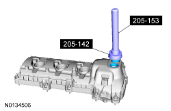
Engine Upper
Engine Front
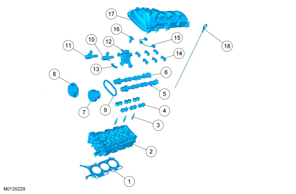
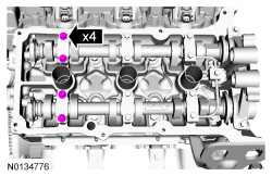
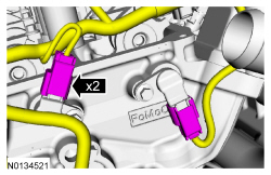
Engine Upper - LH Cylinder Head
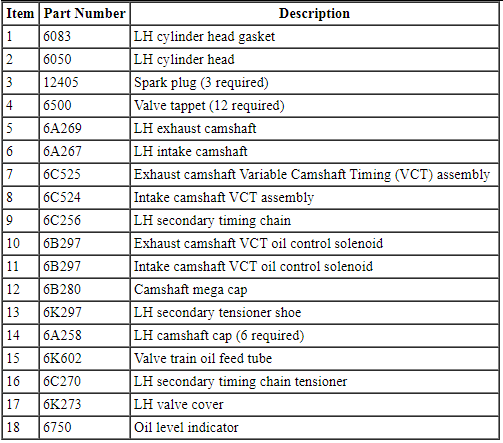
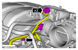
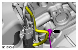
Engine Upper - RH Cylinder Head
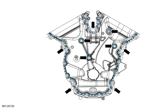
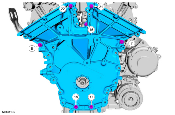
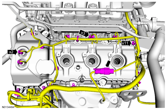
Timing Drive Components
Lower Engine Block (View 1)
Lower Engine Block (View 2)
NOTICE: During engine repair procedures, cleanliness is extremely important. Any foreign material, including any material created while cleaning gasket surfaces that enters the oil passages, coolant passages or the oil pan, may cause engine failure.
NOTE: Assembly of the engine requires various inspections/measurements of the engine components (engine block, crankshaft, connecting rods, pistons and piston rings). These inspections/measurements will aid in determining if the engine components will require replacement. For additional information, refer to Section 303-00.
NOTE: If the cylinder head(s) is replaced, a new secondary timing chain tensioner will need to be installed.
All vehicles
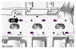
- Using a hexagonal screwdriver, install the 6 piston oil cool valves.
- Tighten to 4 Nm (35 lb-in).
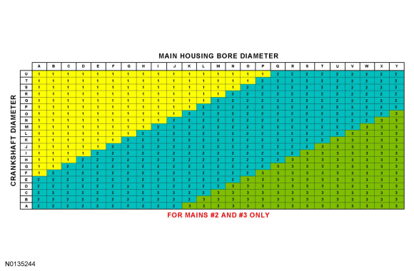
- NOTE: This procedure is for selecting bearings using a new
crankshaft.
Select the crankshaft main bearings for each crankshaft journal.
- Read the code on the crankshaft flange.
- Read the code on the cylinder block face.
- The first letter after the first asterisk makes up the code for main No. 1 and the next letter for main No. 2. The first letter after the second asterisk makes up the code for main No. 3 and the last letter for main No. 4.
- NOTE: This chart is for selecting main bearings 1 and 4 only, the
remaining bearings will be selected using a different chart in the next
step.
Using the data recorded earlier and the Bearing Select Fit Chart, Standard Bearings, determine the required bearing grade for main bearings 1 and 4.
- Read the first letter of the engine block main bearing code and the first letter of the crankshaft main bearing code.
- Read down the column below the engine block main bearing code letter and across the row next to the crankshaft main bearing code letter, until the 2 intersect. This is the required bearing grade(s) for the No. 1 crankshaft main bearing.
- As an example, if the engine block code letter is "F" and the crankshaft code letter is "P", the correct bearing grade for this main bearing is a "1" for the upper bearing and a "2" for the lower bearing.
- Repeat the above steps using the fourth letter of the block and crankshaft codes to select the No. 4 bearing.

- NOTE: This chart is for selecting main bearings 2 and 3 only.
Using the data recorded earlier and the Bearing Select Fit Chart, Standard Bearings, determine the required bearing grade for main bearings 2 and 3.
- Read the second letter of the engine block main bearing code and the second letter of the crankshaft main bearing code.
- Read down the column below the engine block main bearing code letter and across the row next to the crankshaft main bearing code letter, until the 2 intersect. This is the required bearing grade for the No. 2 crankshaft main bearing.
- As an example, if the engine block code letter is "F" and the crankshaft code letter is "P", the correct bearing grade for this main bearing is "1".
- Repeat the above steps using the third letter of the block and crankshaft codes to select the No. 3.
- NOTICE: The rod cap installation must keep the same
orientation as marked during disassembly or engine damage may occur.
Using the original connecting rod cap bolts, install the connecting rod caps and bolts.
- Tighten the bolts in 3 stages.
- Stage 1: Tighten to 23 Nm (17 lb-ft).
- Stage 2: Tighten to 43 Nm (32 lb-ft).
- Stage 3: Tighten an additional 90 degrees.
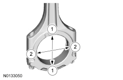
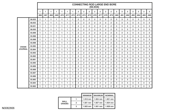
- Measure the connecting rod large end bore in 2 directions.
- Remove the bolts and the rod cap.
- Discard the connecting rod cap bolts.
- Remove the bolts and the rod cap.
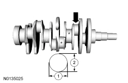
- Measure each of the crankshaft connecting rod bearing journal diameters in at least 2 directions.
- Using the chart, select the correct connecting rod bearings for each crankshaft connecting rod journal.
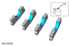
- NOTE: Before assembling the cylinder block, all sealing surfaces
must be free of chips, dirt, paint and foreign material. Also, make sure the
coolant and oil passages are clear.
Lubricate the upper crankshaft main bearings with clean engine oil and install the 4 upper crankshaft main bearings in the cylinder block.
- NOTE: Do not install the upper thrust bearings until the
crankshaft is installed.
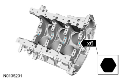
NOTE: Lubricate the thrust surfaces of the crankshaft with clean engine oil.
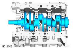
Install the crankshaft onto the upper main bearings.
- NOTE: Make sure the side of the thrust washer, with the wide oil
grooves, faces the crankshaft thrust surface.
Push the crankshaft rearward and install the rear crankshaft upper thrust washer at the back of the No. 4 rear bulkhead.
- NOTE: Make sure the side of the thrust washer, with the wide oil
grooves, faces the crankshaft thrust surface.
Push the crankshaft forward and install the front crankshaft upper thrust washer at the front of the No. 4 rear bulkhead.
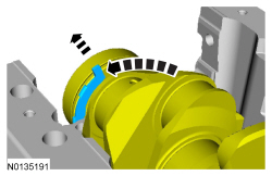
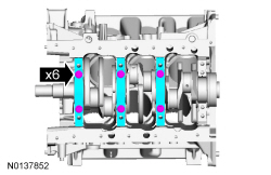
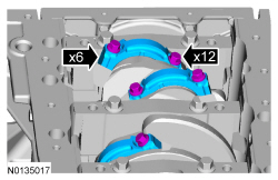
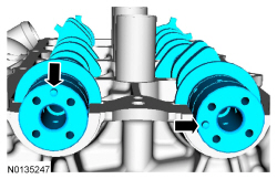
- Lubricate the crankshaft lower main bearings with clean engine oil and install them into the main bearing caps. Visually check seating and squareness of the bearings to make sure of proper seating in caps.
- Position the No. 1, No. 2 and No. 3 main bearing caps on the cylinder block and, keeping the caps as square as possible, alternately draw the caps down evenly using the new bolts until the main bearing caps are seated.
- NOTE: Make sure the side of the thrust washer, with the wide oil
grooves, faces the crankshaft thrust surface.
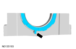
NOTE: To aid in assembly, apply petroleum jelly to the back of the crankshaft thrust washer.
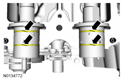
Install the lower crankshaft thrust washer to the back side of the No. 4 rear main bearing cap, with the tab aligned with the cutout in the main bearing cap.
- Position main bearing cap No. 4 on the cylinder block and keeping the cap as square as possible, alternately draw the cap down evenly using the new bolts until the main bearing cap is seated.
- NOTE: While tightening the main bearing vertical bolts, push the
crankshaft forward and the No. 4 main bearing cap rearward to seat the
crankshaft thrust washers.
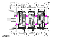
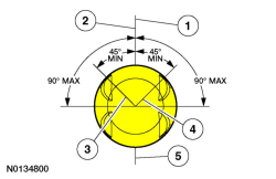
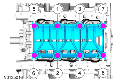
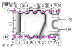
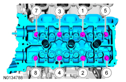
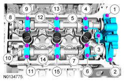
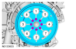
Tighten the main bearing bolts in the sequence shown in 2 stages.
- Stage 1: Tighten fasteners 1 through 8 to 33 Nm (24 lb-ft).
- Stage 2: Tighten fasteners 1 through 8 an additional 135 degrees.
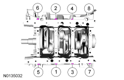
- Install the new 8 main bearing cap side bolts. Tighten in the sequence
shown in 2 stages.
- Stage 1: Tighten fasteners 1 through 8 to 45 Nm (33 lb-ft).
- Stage 2: Tighten fasteners 1 through 8 an additional 90 degrees.
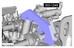
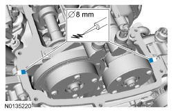
- Using the Dial Indicator Gauge with Holding Fixture, measure crankshaft
end play.
- Position the crankshaft to the rear of the cylinder block.
- Zero the Dial Indicator Gauge.
- Move the crankshaft to the front of the cylinder block. Note and record the crankshaft end play.
- NOTICE: The rod cap installation must keep the same
orientation as marked during disassembly or engine damage may occur.
Prepare the connecting rod and cap.
- Insert the new bolts in the rod cap.
- Insert the upper and lower rod bearings into the rod and cap.
- Before installing the pistons into the cylinder block, verify proper
ring gap location.
- Center line of the piston parallel to the wrist pin bore
- Upper compression ring gap location
- Upper oil control segment ring gap location
- Lower oil control segment ring gap location
- Expander ring and lower compression ring gap location
- NOTICE: Be sure not to scratch the cylinder wall or crankshaft
journal with the connecting rod. Push the piston down until the connecting
rod bearing seats on the crankshaft journal.
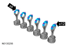
NOTE: The next 3 steps are for all 6 connecting rods, rod caps and pistons. Only 1 connecting rod, rod cap and piston is shown.
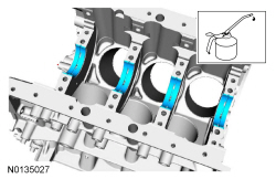
NOTE: Lubricate the pistons, piston rings, connecting rod bearings and the entire cylinder bores with clean engine oil.
NOTE: Make sure the piston rings are positioned to specifications for installation. For additional information, refer to Piston in this section.
NOTE: If the piston and or connecting rod are being installed new, the piston rod orientation marks and the arrow on the top of the dome of the piston should be facing toward the front of the engine block.
NOTE: If the piston and connecting rod are to be reinstalled, they must be installed in the same orientation as disassembled.
Using the Piston Ring Compressor, install the piston and connecting rod assemblies.- Seat the connecting rod on the crankshaft journal.
- NOTICE: The rod cap installation must keep the same
orientation as marked during disassembly or engine damage may occur.
NOTE: After installation of each piston, connecting rod, rod cap and bolts, rotate the crankshaft to verify smooth operation.
Install the 6 connecting rod cap and the 12 bolts.- Tighten the bolts in 3 stages.
- Stage 1: Tighten to 23 Nm (17 lb-ft).
- Stage 2: Tighten to 43 Nm (32 lb-ft).
- Stage 3: Tighten an additional 90 degrees.
- Repeat the previous 3 steps and this step until all 6 piston, connecting rod and connecting rod cap assemblies are installed.
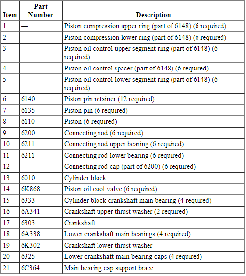
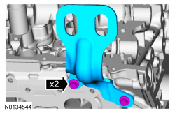
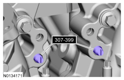
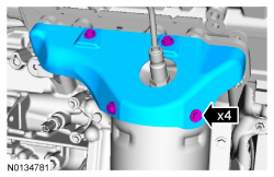
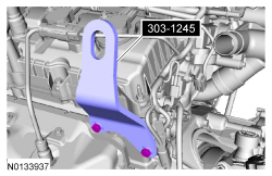
- Install the main bearing cap support brace and the new bolts. Tighten in
the sequence shown in 2 steps.
- Stage 1: Tighten to 24 Nm (18 lb-ft).
- Stage 2: Tighten an additional 180 degrees.
- NOTICE: Failure to use Motorcraft High Performance Engine RTV
Silicone may cause the engine oil to foam excessively and result in serious
engine damage.
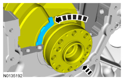
NOTE: The crankshaft rear seal retainer must be installed and the bolts tightened within 4 minutes of sealant application.
NOTE: The stamped steel crankshaft rear seal retainer plate comes with the crankshaft rear seal.
Apply a 3 mm (0.11 in) bead of Motorcraft High Performance Engine RTV Silicone to the sealing surface of the crankshaft rear seal retainer.
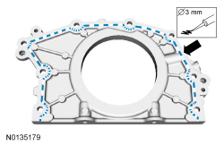
- NOTE: Lubricate the crankshaft rear seal with clean engine oil.
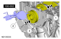
Install the crankshaft rear seal retainer and the 8 bolts.
- Tighten in the sequence shown to 10 Nm (89 lb-in).
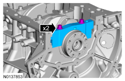
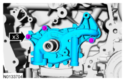
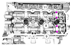
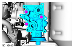
- Install the oil pump and the 3 bolts.
- Tighten to 10 Nm (89 lb-in).
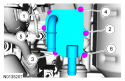
- Using a new O-ring seal, install the oil pump screen and pickup tube and
the 2 bolts.
- Tighten to 10 Nm (89 lb-in).
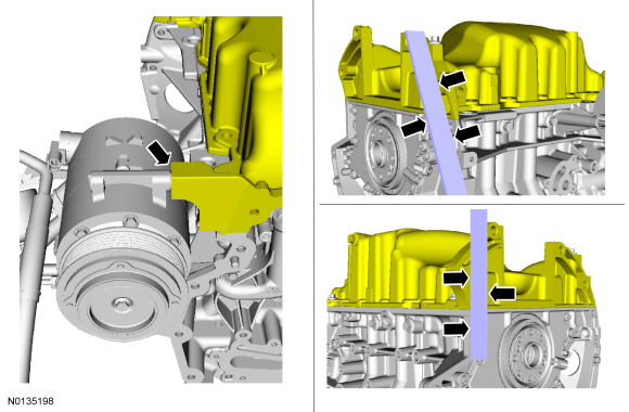
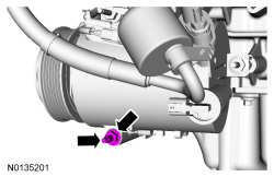
- NOTE: The A/C compressor must be installed on the cylinder block
and the 2 bolts tightened prior to installing the oil pan.
Install the A/C compressor and the 2 bolts.
- Tighten to 25 Nm (18 lb-ft).
- NOTICE: Failure to use Motorcraft High Performance Engine RTV
Silicone may cause the engine oil to foam excessively and result in serious
engine damage.
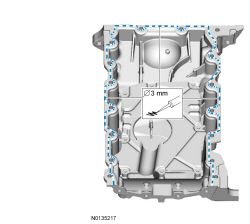
Apply a 3 mm (0.11 in) bead of Motorcraft High Performance Engine RTV Silicone to the sealing surface of the oil pan.
- NOTICE: Failure to use Motorcraft High Performance Engine RTV
Silicone may cause the engine oil to foam excessively and result in serious
engine damage.
NOTE: The oil pan and the 4 specified bolts must be installed and the oil pan aligned to the cylinder block and A/C compressor within 4 minutes of sealant application. Final tightening of the oil pan bolts must be carried out within 60 minutes of sealant application.
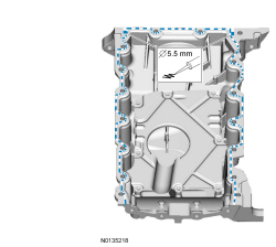
Apply a 5.5 mm (0.21 in) bead of Motorcraft High Performance Engine RTV Silicone to the 2 crankshaft seal retainer plate-to-cylinder block joint areas on the sealing surface of the oil pan.
- NOTE: The oil pan and the 4 specified bolts must be installed
within 4 minutes of the start of sealant application.
Install the oil pan and bolts 10, 11, 13 and 14.
- Tighten the bolts in the sequence shown to 3 Nm (27 lb-in).
- Loosen the bolts 180 degrees.
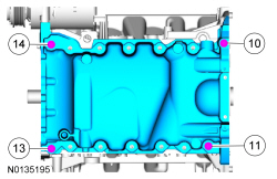
- Align the oil pan to the cylinder block and the A/C compressor.
- Position the oil pan so the mounting boss is against the A/C compressor and using a straightedge, align the oil pan flush with the rear of the cylinder block at the 2 areas shown.
- Tighten bolts 10, 11, 13 and 14 in the sequence shown, to 3 Nm (27 lb-in).
- Install the remaining oil pan bolts. Tighten all the oil pan bolts in
the sequence shown.
- Tighten the large bolts (1-14) to 24 Nm (18 lb-ft).
- Tighten the small bolts (15 and 16) to 10 Nm (89 lb-in).
- Install the A/C compressor mounting stud and nut.
- Tighten the stud to 9 Nm (80 lb-in) and the nut to 25 Nm (18 lb-ft).
- Install the coolant pump and the 8 bolts. Tighten in the sequence shown
in 2 stages:
- Stage 1: Tighten to 10 Nm (89 lb-in).
- Stage 2: Tighten an additional 45 degrees.
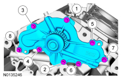
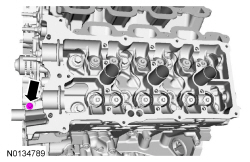
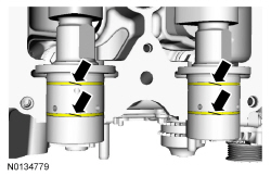
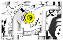
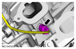
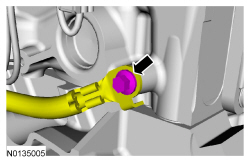
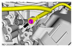
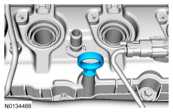
- Install the Knock Sensor (KS) and the 2 bolts.
- Tighten to 20 Nm (177 lb-in).
- NOTE: Apply clean engine coolant to the O-ring seal prior to
installation.
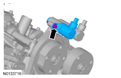
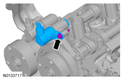
Using a new O-ring seal, install the coolant inlet tube and thermostat assembly.
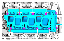
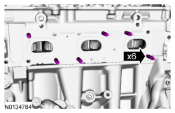
- Install a new gasket, the RH cylinder head and 8 new bolts. Tighten in
the sequence shown in 5 stages:
- Stage 1: Tighten to 20 Nm (177 lb-in).
- Stage 2: Tighten to 35 Nm (26 lb-ft).
- Stage 3: Tighten 90 degrees.
- Stage 4: Tighten 90 degrees
- Stage 5: Tighten 45 degrees.
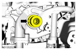
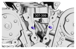
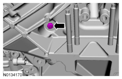
- Install the M6 bolt.
- Tighten to 10 Nm (89 lb-in).
- NOTE: If the cylinder head is replaced, a new secondary timing
chain tensioner will need to be installed.
Install a new gasket, the LH cylinder head and 8 new bolts. Tighten in the sequence shown in 5 stages:
- Stage 1: Tighten to 20 Nm (177 lb-in).
- Stage 2: Tighten to 35 Nm (26 lb-ft).
- Stage 3: Tighten 90 degrees.
- Stage 4: Tighten 90 degrees
- Stage 5: Tighten 45 degrees.
- Install the M6 bolt.
- Tighten to 10 Nm (89 lb-in).
- NOTE: The valve tappets must be installed in their original
positions.
NOTE: Coat the valve tappets with clean engine oil prior to installation.
NOTE: LH shown, RH similar.
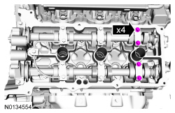
Install the 24 valve tappets.
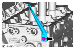
- NOTE: Align the bracket with the index mark made during removal.
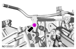
Install the upper intake manifold bracket and the bolt.
- Tighten to 10 Nm (89 lb-in).
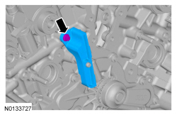
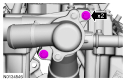
- Install the engine lifting eye and the 2 bolts.
- Tighten to 24 Nm (18 lb-ft).
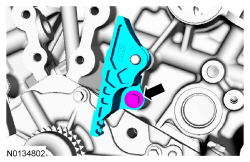
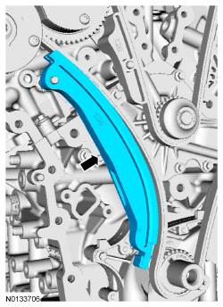
- Install the RH primary timing chain guide and the bolt.
- Tighten to 10 Nm (89 lb-in).
- NOTICE: The crankshaft must remain in the freewheeling
position (crankshaft dowel pin at 9 o'clock) until after the camshafts are
installed and the valve clearance is checked/adjusted. Do not turn the
crankshaft until instructed to do so. Failure to follow this process will
result in severe engine damage.
Position the crankshaft dowel pin in the 9 o'clock position.
- NOTE: Coat the camshafts with clean engine oil prior to
installation.
Position the camshafts onto the RH cylinder head in the neutral position as shown.
- NOTICE: The camshaft seal gaps must be at the 12 o'clock
position or damage to the engine may occur.
Position the 4 RH camshaft seals gaps as shown.
- NOTE: Cylinder head camshaft bearing caps are numbered to verify
that they are assembled in their original positions.
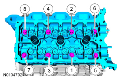
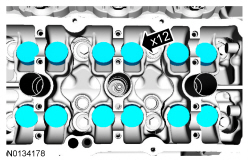
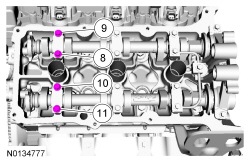
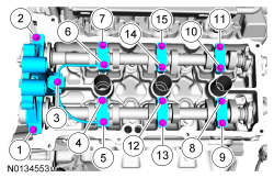
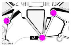
Install the 6 RH camshaft caps, mega cap, valve train oil tube and the 15 bolts in the sequence shown.
- Tighten to 8 Nm (71 lb-in) then additional 45 degrees.
- Loosen the 4 RH camshaft caps bolts.
- Tighten the 4 RH camshaft caps bolts in the sequence shown.
- Tighten bolts 8, 9, 10 and 11 to 8 Nm (71 lb-in) then additional 45 degrees.
- NOTICE: If any components are installed new, the engine valve
clearance must be checked/adjusted or engine damage may occur.
NOTE: Use a camshaft sprocket bolt to turn the camshafts.
Using a feeler gauge, confirm that the valve tappet clearances are within specification. If valve tappet clearances are not within specification, the clearance must be adjusted by installing new valve tappet(s) of the correct size. For additional information, refer to Valve Clearance Check in this section.

- Remove the 3 bolts and the RH valve train oil tube.
- Rotate the RH camshafts to the TDC position as shown.
- NOTE: The Camshaft Holding Tool will hold the camshafts in
the TDC position.
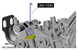
Install the Camshaft Holding Tool onto the flats of the RH camshafts.
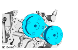
- Compress the RH secondary timing chain tensioner and install the Secondary Chain Hold Down to retain the tensioner in the collapsed position.
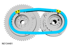
- Assemble the RH VCT assembly, the RH exhaust camshaft sprocket and the
RH secondary timing chain.
- Align the colored links with the timing marks.
- NOTE: It may be necessary to rotate the camshafts slightly, to
install the RH secondary timing assembly.
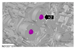
Position the 2 RH VCT assemblies and secondary timing chain onto the camshafts by aligning the holes in the VCT assemblies with the dowel pins in the camshafts.
- Install the 2 new RH VCT bolts and tighten in 4 stages.
- Stage 1: Tighten to 40 Nm (30 lb-ft).
- Stage 2: Loosen one full turn.
- Stage 3: Tighten to 25 Nm (18 lb-ft).
- Stage 4: Tighten an additional 180 degrees.
- NOTE: The 2 VCT oil control solenoids are removed for clarity.
Compress the RH secondary timing chain tensioner and remove the Secondary Chain Hold Down.
- Make sure the secondary timing chain is centered on the timing chain tensioner guides.
- NOTE: Coat the camshafts with clean engine oil prior to
installation.
Position the camshafts onto the LH cylinder head in the neutral position as shown.
- NOTICE: The camshaft seal gaps must be at the 12 o'clock
position or damage to the engine may occur.
Position the 4 LH camshaft seals gaps as shown.
- NOTE: Cylinder head camshaft bearing caps are numbered to verify
that they are assembled in their original positions.
Install the 6 LH camshaft caps, mega cap, valve train oil tube and the 15 bolts in the sequence shown.
- Tighten to 8 Nm (71 lb-in) then additional 45 degrees.
- Loosen the 4 LH camshaft caps bolts.
- Tighten the 4 LH camshaft caps bolts in the sequence shown.
- Tighten bolts 8, 9, 10 and 11 to 8 Nm (71 lb-in) then additional 45 degrees.
- NOTICE: If any components are installed new, the engine valve
clearance must be checked/adjusted or engine damage may occur.
NOTE: Use a camshaft sprocket bolt to turn the camshafts.
Using a feeler gauge, confirm that the valve tappet clearances are within specification. If valve tappet clearances are not within specification, the clearance must be adjusted by installing new valve tappet(s) of the correct size. For additional information, refer to Valve Clearance Check in this section.
- Remove the 3 bolts and the LH valve train oil tube.
- Rotate the LH camshafts to the TDC position as shown.
- NOTE: The Camshaft Holding Tool will hold the camshafts in the
Top Dead Center (TDC) position.
Install the Camshaft Holding Tool onto the flats of the LH camshafts.
- Compress the LH secondary timing chain tensioner and install the Secondary Chain Hold Down to retain the tensioner in the collapsed position.
- Assemble the 2 LH VCT assemblies and the LH secondary timing chain.
- Align the colored links with the timing marks.
- NOTE: It may be necessary to rotate the camshafts slightly, to
install the LH secondary timing assembly.
Position the 2 LH VCT assemblies and secondary timing chain onto the camshafts by aligning the holes in the VCT assemblies with the dowel pins in the camshafts.
- Install the 2 new LH VCT bolts and tighten in 4 stages.
- Stage 1: Tighten to 40 Nm (30 lb-ft).
- Stage 2: Loosen one full turn.
- Stage 3: Tighten to 25 Nm (18 lb-ft).
- Stage 4: Tighten an additional 180 degrees.
- NOTE: The 2 VCT oil control solenoids are removed for clarity.
Compress the LH secondary timing chain tensioner and remove the Secondary Chain Hold Down.
- Make sure the secondary timing chain is centered on the timing chain tensioner guides.
- Install the LH upper primary timing chain guide and the bolt.
- Tighten to 10 Nm (89 lb-in).
- Rotate the crankshaft clockwise 60 degrees to the TDC position (crankshaft dowel pin at 11 o'clock).
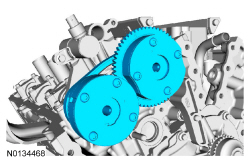
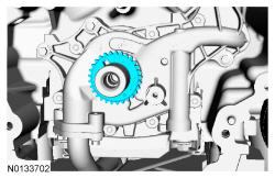
- Install the crankshaft timing chain sprocket.
- NOTE: It may be necessary to rotate the camshafts slightly, to
align the timing marks.
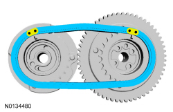
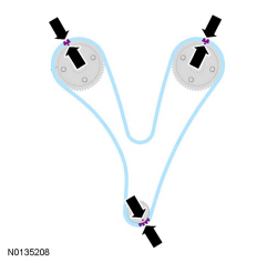
Install the primary timing chain with the colored links aligned with the timing marks on the VCT assemblies and the crankshaft sprocket.
- Install the lower LH primary timing chain guide and the 2 bolts.
- Tighten to 10 Nm (89 lb-in).

- Install the primary timing chain tensioner arm.
- Reset the primary timing chain tensioner.
- Release the ratchet detent.
- Using a soft-jawed vise, compress the ratchet plunger.
- Align the hole in the ratchet plunger with the hole in the tensioner housing.
- Install a suitable lockpin.
- NOTE: It may be necessary to rotate the camshafts slightly to
remove slack from the timing chain to install the tensioner.
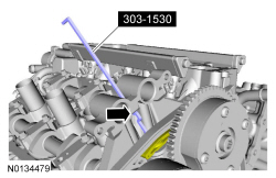
Install the primary tensioner and the 2 bolts.
- Tighten to 10 Nm (89 lb-in).
- Remove the lockpin.
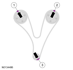
- As a post-check, verify correct alignment of all timing marks.
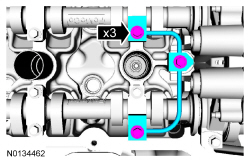
- There are 48 links in between the RH intake VCT assembly colored link (1) and the LH intake VCT assembly colored link (2).
- There are 35 links in between LH intake VCT assembly colored link (2) and the 2 crankshaft sprocket links (3).
- NOTICE: Do not use excessive force when installing the
Variable Camshaft Timing (VCT) oil control solenoid. Damage to the mega cap
could cause the cylinder head to be inoperable. If difficult to install
the VCT oil control solenoid, inspect the bore and VCT oil control solenoid
to ensure there are no burrs, sharp edges or contaminants present on the
mating surface. Only clean the external surfaces as necessary.
NOTE: A slight twisting motion will aid in the installation of the VCT oil control solenoid.
NOTE: Keep the VCT oil control solenoid clean of dirt and debris.
Install the LH intake VCT oil control solenoid and the bolt.- Tighten to 8 Nm (71 lb-in) then an additional 20 degrees.
- NOTICE: Do not use excessive force when installing the
Variable Camshaft Timing (VCT) oil control solenoid. Damage to the mega cap
could cause the cylinder head to be inoperable. If difficult to install
the VCT oil control solenoid, inspect the bore and VCT oil control solenoid
to ensure there are no burrs, sharp edges or contaminants present on the
mating surface. Only clean the external surfaces as necessary.
NOTE: A slight twisting motion will aid in the installation of the VCT oil control solenoid.
NOTE: Keep the VCT oil control solenoid clean of dirt and debris.
Install the RH intake VCT oil control solenoid and the bolt.- Tighten to 8 Nm (71 lb-in) then an additional 20 degrees.
- Remove the RH Camshaft Holding Tool.

- Install the RH valve train oil tube and the 3 bolts and tighten in 2
stages.
- Stage 1: Tighten to 8 Nm (71 lb-in).
- Stage 2: Tighten an additional 45 degrees.

- Remove the LH Camshaft Holding Tool.

- Install the LH valve train oil tube and the 3 bolts and tighten in 2
stages.
- Stage 1: Tighten to 8 Nm (71 lb-in).
- Stage 2: Tighten an additional 45 degrees.

- NOTICE: Only use a 3M Roloc Bristle Disk (2-in white, part
number 07528) to clean the engine front cover. Do not use metal scrapers,
wire brushes or any other power abrasive disk to clean front cover.
Clean the engine front cover using a 3M Roloc Bristle Disk (2-in white, part number 07528) in a suitable tool turning at the recommended speed of 15,000 rpm.
- Thoroughly wash the engine front cover to remove any foreign material, including any abrasive particles created during the cleaning process.
- NOTICE: Place clean, lint-free shop towels over exposed engine
cavities. Carefully remove the towels so foreign material is not dropped
into the engine. Any foreign material (including any material created while
cleaning gasket surfaces) that enters the oil passages or the oil pan, may
cause engine failure.
NOTICE: Do not use wire brushes, power abrasive discs or 3M Roloc Bristle Disk (2-in white part number 07528) to clean the sealing surfaces of engine block, cylinder heads, and oil pan. These tools can cause contamination that will cause premature engine failure. Remove all traces of the gasket.
Clean the sealing surfaces of the cylinder heads, the cylinder block and the oil pan in the following sequence.- Remove any large deposits of silicone or gasket material.
- Apply silicone gasket remover and allow to set for several minutes.
- Remove the silicone gasket remover. A second application of silicone gasket remover may be required if residual traces of silicone or gasket material remain.
- Apply metal surface prep to remove any remaining traces of oil or coolant and to prepare the surfaces to bond. Do not attempt to make the metal shiny. Some staining of the metal surfaces is normal.
- Make sure the 2 locating dowel pins are seated correctly in the cylinder block.
- Install the Alignment Pins.
- NOTICE: Failure to use Motorcraft High Performance Engine RTV
Silicone may cause the engine oil to foam excessively and result in serious
engine damage.
NOTE: The engine front cover and bolts 7, 8, 15, 17, 18, 21 and 22 must be installed within 4 minutes of the initial sealant application. The remainder of the engine front cover bolts must be installed and tightened within 35 minutes of the initial sealant application. If the time limits are exceeded, the sealant must be removed, the sealing area cleaned and sealant reapplied. To clean the sealing area, use silicone gasket remover and metal surface prep. Failure to follow this procedure can cause future oil leakage.
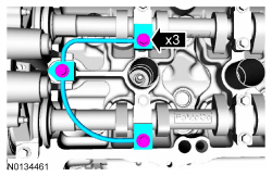
Apply a 3.0 mm (0.11 in) bead of Motorcraft High Performance Engine RTV Silicone to the engine front cover sealing surfaces including the 4 inner bolt bosses.- Apply a 5.5 mm (0.21 in) bead of Motorcraft High Performance Engine RTV Silicone to the oil pan-to-cylinder block joint and the cylinder head-to-cylinder block joint areas of the engine front cover in 5 places as indicated.
- NOTE: Make sure the 2 locating dowel pins are seated correctly in
the cylinder block.
Install the engine front cover and bolts 7, 8, 15, 17, 18, 21 and 22.
- Tighten in sequence to 3 Nm (27 lb-in).
- Remove the Alignment Pins.
- NOTE: Do not tighten the bolt at this time.
Install the M6 engine front cover bolt.
- NOTE: Do not tighten the bolts at this time.
Install the 3 M10 engine front cover bolts.
- NOTICE: Do not expose the Motorcraft High Performance Engine
RTV Silicone to engine oil for at least 90 minutes after installing the
engine front cover. Failure to follow this instruction may cause oil
leakage.
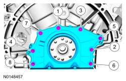
Install the remaining engine front cover bolts. Tighten all of the engine front cover bolts and engine mount bracket bolts in the sequence shown in 7 stages:
- Stage 1: Tighten bolts 1 thru 22 to 10 Nm (89 lb-in).
- Stage 2: Tighten bolts 23, 24 and 25 to 15 Nm (133 lb-in).
- Stage 3: Tighten bolt 26 to 10 Nm (89 lb-in).
- Stage 4: Loosen bolt 26 one full turn.
- Stage 5: Tighten bolts 23, 24 and 25 to 30 Nm (22 lb-ft) plus an additional 90 degrees.
- Stage 6: Tighten bolts 1 thru 22 to 20 Nm (177 lb-in) plus an additional 45 degrees.
- Stage 7: Tighten bolt 26 to 10 Nm (89 lb-in) plus an additional 45 degrees.
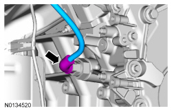
- NOTE: Apply thread sealant with PTFE to the Engine Oil Pressure
(EOP) switch threads.
Install the EOP switch.
- Tighten to 14 Nm (124 lb-in) plus an additional 180 degrees.
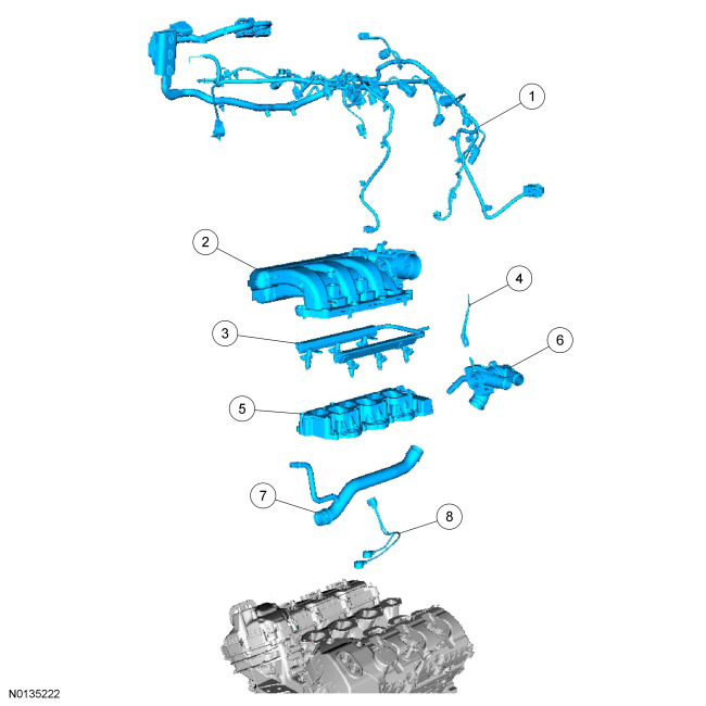
- Install and connect the Cylinder Head Temperature (CHT) sensor jumper harness.
- NOTICE: If the engine is repaired or replaced because of upper
engine failure, typically including valve or piston damage, check the intake
manifold for metal debris. If metal debris is found, install a new intake
manifold. Failure to follow these instructions can result in engine damage.
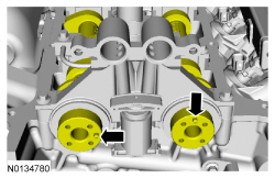
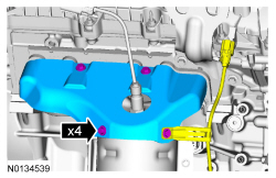
Using new intake manifold and thermostat housing gaskets, install the lower intake manifold and the 10 bolts.
- Tighten in the sequence shown to 10 Nm (89 lb-in).
- Install the fuel supply tube-to-engine front cover bolt.
- Tighten to 10 Nm (89 lb-in).
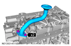
- Install the 2 thermostat housing-to-lower intake manifold bolts.
- Tighten to 10 Nm (89 lb-in).
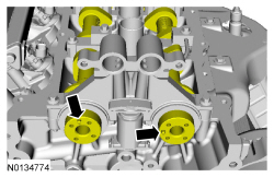
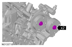
- NOTE: Lubricate the 2 Camshaft Position (CMP) sensor O-ring seals
with clean engine oil.
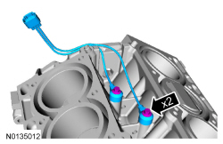
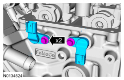
Install the 2 RH CMP sensors and the 2 bolts.
- Tighten to 10 Nm (89 lb-in).
- NOTE: Lubricate the 2 CMP sensor O-ring seals with clean engine
oil.
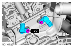
Install the 2 LH CMP sensors and the 2 bolts.
- Tighten to 10 Nm (89 lb-in).
- Install the cover and the pin-type retainer.
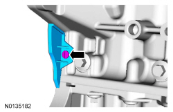
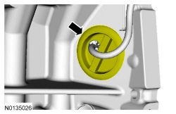
- Install the LH cylinder block drain plug.
- Tighten to 16 Nm (142 lb-in) plus an additional 180 degrees.
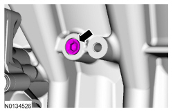
- Install the RH cylinder block drain plug or, if equipped, the block
heater.
- Tighten the cylinder block drain plug to 10 Nm (89 lb-in) plus an additional 720 degrees.
- Tighten the block heater to 40 Nm (30 lb-ft).
Front Wheel Drive (FWD) vehicles
- Install 6 new RH exhaust manifold studs.
- Tighten to 12 Nm (106 lb-in).
- NOTICE: Failure to tighten the exhaust manifold nuts to
specification a second time will cause the exhaust manifold to develop an
exhaust leak.
Using a new gasket, install the RH exhaust manifold and 6 new nuts. Tighten in 2 stages in the sequence shown:
- Stage 1: Tighten to 20 Nm (177 lb-in).
- Stage 2: Tighten to 25 Nm (18 lb-ft).
- Install the RH catalytic converter heat shield, Catalyst Monitor Sensor
(CMS) wiring harness bracket and the 4 bolts.
- Tighten to 10 Nm (89 lb-in).
All vehicles
- Install 6 new LH exhaust manifold studs.
- Tighten to 12 Nm (106 lb-in).
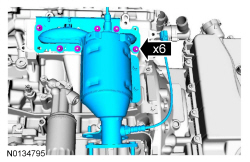
- Using a new gasket, install the LH catalytic converter and 3 new lower
LH catalytic converter manifold-to-cylinder head nuts.
- Install the 3 new upper LH catalytic converter manifold-to-cylinder head nuts and tighten to 25 Nm (18 lb-ft).
- Tighten the 3 lower LH catalytic converter manifold-to-cylinder head nuts to 25 Nm (18 lb-ft).
- Install the LH exhaust heat shield and the 3 bolts.
- Tighten to 10 Nm (89 lb-in).
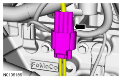
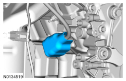
- Position the wiring harness onto the engine and connect the EOP switch electrical connector and the wiring harness pin-type retainer.
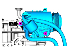
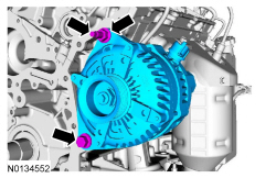
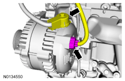
- Install the generator stud, generator and the nut and bolt.
- Tighten the stud to 8 Nm (7 lb-in).
- Tighten the nut and bolt to 47 Nm (35 lb-ft).
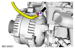
- Connect the generator B+ cable and install the nut.
- Tighten to 17 Nm (150 lb-in).
- Position back the generator B+ cable cover and connect the generator electrical connector.
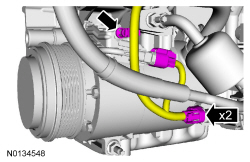
- Connect the 2 A/C compressor electrical connectors.
- Attach the A/C wiring harness retainer.
- NOTE: Oil filter adapter with oil cooler shown, oil filter
adapter without oil cooler similar.
Using a new gasket, install the oil filter adapter and the 3 bolts.
- Tighten to 10 Nm (89 lb-in) plus an additional 45 degrees.
- If equipped, using a new gasket, install the oil cooler and the 6 bolts.
- Tighten in the sequence shown to 10 Nm (89 lb-in).
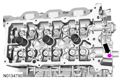
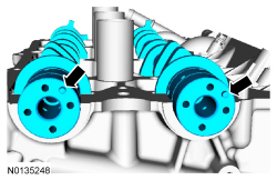
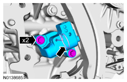
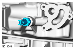
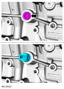
- Install the Crankshaft Position (CKP) sensor and install the bolt.
- Tighten to 10 Nm (89 lb-in).
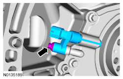
- Connect the CKP sensor electrical connector.

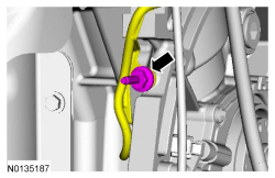
- Install the wiring harness grommet.
- Install the wiring harness retainer stud bolt.
- Tighten to 10 Nm (89 lb-in).
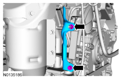
- Install the heat shield, the nut and the bolt.
- Tighten to 10 Nm (89 lb-in).
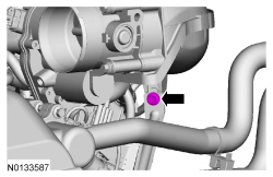
- Install the ground cable and the bolt.
- Tighten to 10 Nm (89 lb-in).
- Connect the 2 RH Camshaft Position Camshaft Position (CMP) sensor electrical connectors.
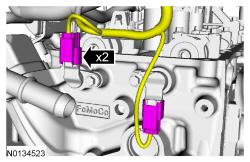
- Connect the KS electrical connector.
- NOTE: Installation of new seals is only required if damaged seals
were removed.
Using the VCT Spark Plug Tube Seal Installer and Handle, install new RH spark plug tube seals.
- NOTE: Installation of new seals is only required if damaged seals
were removed.
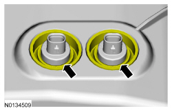
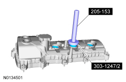
Using the Differential Bearing Cone Installer and Handle, install new RH VCT solenoid seal(s).
- NOTICE: Failure to use the correct Motorcraft High
Performance Engine RTV Silicone may cause the engine oil to foam excessively
and result in serious engine damage.
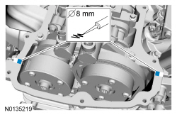
NOTE: If the valve cover is not installed and the fasteners tightened within 4 minutes, the sealant must be removed and the sealing area cleaned. To clean the sealing area, use silicone gasket remover and metal surface prep. Failure to follow this procedure can cause future oil leakage.
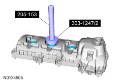
Apply an 8 mm (0.31 in) bead of Motorcraft High Performance Engine RTV Silicone to the engine front cover-to-RH cylinder head joints.
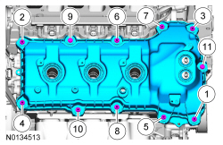
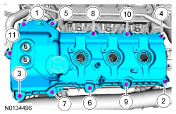
- Using a new gasket, install the RH valve cover and tighten the 2 bolts
and 9 stud bolts.
- Tighten in the sequence shown to 10 Nm (89 lb-in).
- Make sure the VCT seals in the valve cover are below the top of the VCT oil control solenoid electrical connector or the VCT seal may leak oil.
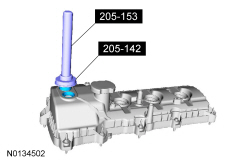
- NOTE: Installation of new seals is only required if damaged seals
were removed.
Using the VCT Spark Plug Tube Seal Installer and Handle, install new LH spark plug tube seals.
- NOTE: Installation of new seals is only required if damaged seals
were removed.
Using the Differential Bearing Cone Installer and Handle, install new LH VCT solenoid seal(s).
- NOTICE: Failure to use Motorcraft High Performance Engine RTV
Silicone may cause the engine oil to foam excessively and result in serious
engine damage.
NOTE: If the valve cover is not installed and the fasteners tightened within 4 minutes, the sealant must be removed and the sealing area cleaned. To clean the sealing area, use silicone gasket remover and metal surface prep. Failure to follow this procedure can cause future oil leakage.
Apply an 8 mm (0.31 in) bead of Motorcraft High Performance Engine RTV Silicone to the engine front cover-to-LH cylinder head joints.
- Using a new gasket, install the LH valve cover and tighten the 4 bolts
and 7 stud bolts.
- Tighten in the sequence shown to 10 Nm (89 lb-in).
- Make sure the VCT seals in the valve cover are below the top of the VCT oil control solenoid electrical connector or the VCT seal may leak oil.

- NOTE: On All-Wheel Drive (AWD) vehicles the Catalyst Monitor
Sensor (CMS) electrical connector will be connected during the engine
installation procedure.
Install the engine wiring harness to the RH valve cover.
- Position the wiring harness and attach the 9 wiring harness retainers to the RH valve cover and stud bolts.
- Connect the CHT sensor wiring harness jumper electrical connector.
- Connect the 3 fuel injector electrical connectors.
- Connect and attach the RH CMS electrical connector.
- Connect the 2 VCT oil control solenoid electrical connectors.
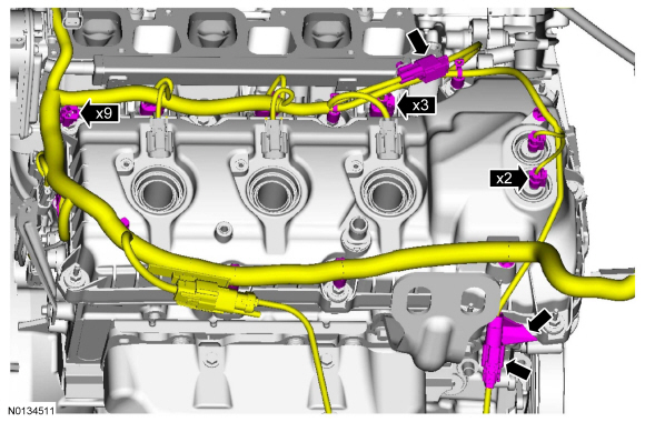
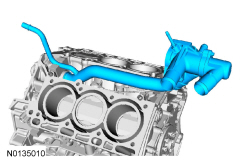
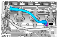
- Install the PCV crankcase vent tube.
- NOTE: Apply a small amount of dielectric grease to the inside of
the ignition coil-on-plug boots before attaching to the spark plugs.
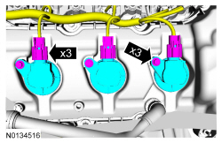
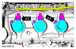
Install the 3 RH coil-on-plugs and the 3 bolts.
- Tighten to 7 Nm (62 lb-in).
- Connect the 3 coil-on-plug electrical connectors.
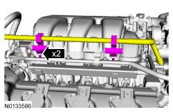
- Using a new gasket, install the intake manifold and the 7 bolts.
- Tighten in the sequence shown in 2 stages.
- Stage 1: Tighten to 10 Nm (89 lb-in).
- Stage 2: Tighten an additional 45 degrees.
- Tighten in the sequence shown in 2 stages.
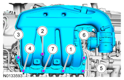
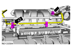
- Install the upper intake manifold support bracket bolt.
- Tighten to 10 Nm (89 lb-in).
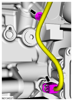
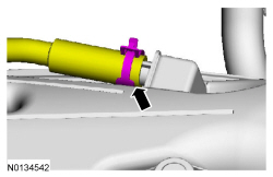
- Attach the 2 coolant tube retainers to the upper intake manifold.
- Connect the crankcase ventilation hose to the upper intake manifold.
- Connect the EVAP vapor tube to the EVAP canister vent solenoid. For
additional information, refer to Section 310-00.
- Attach the EVAP vapor tube to the 2 retainers.
- Connect the EVAP canister vent solenoid and throttle body electrical
connectors.
- Attach the wiring harness pin-type retainer to the upper intake manifold.
- Install the wiring harness retainer to the rear of the LH cylinder head.
- Connect the 2 LH Camshaft Position (CMP) sensor electrical connectors.
- Install the engine wiring harness to the LH valve cover.
- Position the wiring harness and attach the 11 wiring harness retainers to the LH valve cover and stud bolts.
- Connect the 3 fuel injector electrical connectors.
- Connect and attach the LH HO2S electrical connector.
- Connect the 2 VCT oil control solenoid electrical connectors.
- Position the wire harness ground to the engine front cover and install
the bolt.
- Tighten to 10 Nm (89 lb-in).
- Install the oil level indicator.
- NOTE: Apply a small amount of dielectric grease to the inside of
the ignition coil-on-plug boots before attaching to the spark plugs.
Install the 3 LH -coil-on-plugs and the 3 bolts.
- Tighten to 7 Nm (62 lb-in.
- Connect the 3 coil-on-plug electrical connectors.
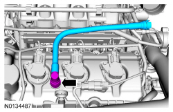
- Install the crankcase vent tube. For additional information, refer to the quick connect coupling procedure in Section 310-00.
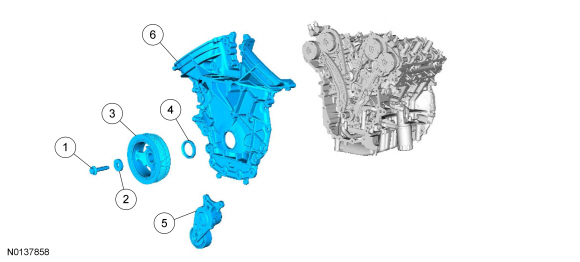
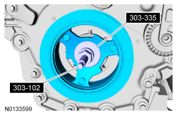
- NOTE: Apply clean engine oil to the crankshaft front seal bore in
the engine front cover.
Using the Crankshaft Vibration Damper Replacer and Front Crankshaft Seal Installer, install a new crankshaft front seal.
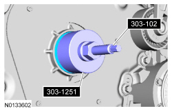
- NOTE: Lubricate the outside diameter sealing surfaces with clean
engine oil.
Using the Crankshaft Vibration Damper Replacer and Front Cover Oil Seal Installer, install the crankshaft pulley.
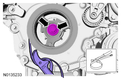
- Using the Strap Wrench, install the crankshaft pulley washer and new
bolt and tighten in 4 stages.
- Stage 1: Tighten to 120 Nm (89 lb-ft).
- Stage 2: Loosen one full turn.
- Stage 3: Tighten to 50 Nm (37 lb-ft).
- Stage 4: Tighten an additional 90 degrees.
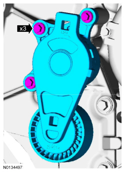
- Install the accessory drive belt tensioner and the 3 bolts.
- Tighten to 11 Nm (97 lb-in).
- If equipped, position the block heater wiring harness onto the engine
and attach all of the harness retainers.
- Connect the block heater electrical connector.
- If equipped, install the block heater heat shield.
- Install the Engine Lift Eye on the LH cylinder head.
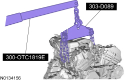
- Using the Floor Crane and Spreader Bar, remove the engine from the stand.
- Install the crankshaft sensor ring.
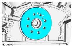
- NOTE: One of the 8 flexplate holes are offset so the flexplate
can only be installed in one position.
Install the flexplate and the 8 bolts.
- Tighten in the sequence shown to 80 Nm (59 lb-ft).
 Disassembly and Assembly of Subassemblies
Cylinder Head
Special Tool(s)
Material
Cylinder Head
NOTE: RH shown, LH similar.
Disassembly
All cylinder heads
NOTE: If the components are to be reinstalled, they must be installed
in ...
 Installation
Engine
Special Tool(s)
Material
All vehicles
Using the Floor Crane and Spreader Bar, align the transaxle to the
engine.
Install the 5 transaxle-to-engine bolts.
Tighten to 48 Nm (35 lb- ...
Other materials:
Stability Control
PRINCIPLES OF OPERATION
WARNING: Vehicle modifications involving braking system,
aftermarket roof racks, suspension, steering system, tire
construction and wheel or tire size may change the handling
characteristics of your vehicle and may adversely affect the
performance of the AdvanceTrac® sy ...
Changing a fuse
Fuses
WARNING: Always replace a fuse with one that has the
specified amperage rating. Using a fuse with a higher amperage
rating can cause severe wire damage and could start a fire.
If electrical components in your
vehicle are not working, a fuse may
have blown. Blown fuses are
identified b ...
General Procedures
Audio Control Module (ACM) Self-Diagnostic Mode
NOTE: If the Audio Front Control Module (ACM) is completely
inoperative (does not power up), the part number decal on the Audio Front
Control Module (ACM) chassis can be used to attain the ACM part number.
Turn the ACM on.
...
