Cylinder Head
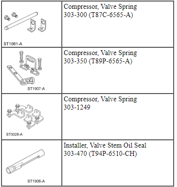
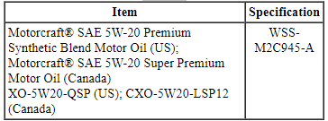
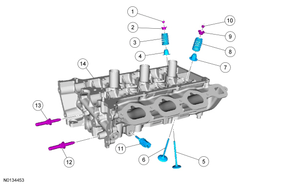
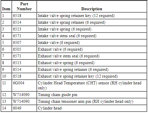
Special Tool(s)
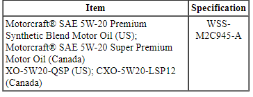
Material
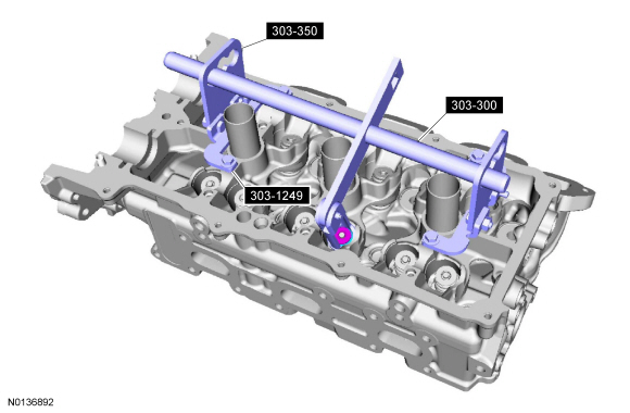
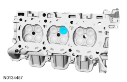
Cylinder Head
NOTE: RH shown, LH similar.
Disassembly
All cylinder heads
NOTE: If the components are to be reinstalled, they must be installed in the same positions. Mark the components for installation into their original locations.
- Using the Valve Spring Compressors, remove the keys, retainer and spring.
- Remove and discard the valve stem seal.
- Remove the valve from the cylinder head.

- Repeat the above steps for each valve.
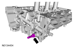
- Remove the timing chain guide pin.
RH cylinder head
- Remove the timing chain tensioner arm pin.

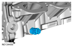
- Remove and discard the Cylinder Head Temperature (CHT) sensor.
Assembly
All cylinder heads
- Install the valve.
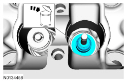
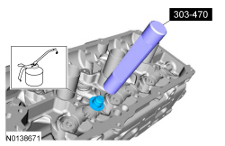
- NOTE: Lubricate the valve stem seal with clean engine oil prior
to installation.
Using the Valve Stem Oil Seal Installer, install a new valve stem seal.
- Using the Valve Spring Compressors, install the valve spring, retainer and key.

- Repeat the above steps for each valve.
- Install the timing chain guide pin.
- Tighten to 10 Nm (89 lb-in).

RH cylinder head
- Install the timing chain tensioner arm pin.
- Tighten to 10 Nm (89 lb-in).
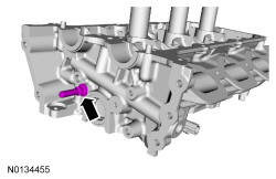
- Install a new CHT sensor.
- Tighten to 10 Nm (89 lb-in).

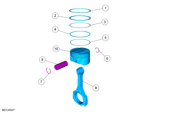
Piston
Material
Disassembly
- Remove the piston rings from the piston.
- Discard the piston rings.
- Remove the 2 piston pin retainers and the piston pin.
- Discard the 2 piston pin retainer clips.
- NOTE: If the piston and connecting rod are to be reinstalled,
they must be assembled in the same orientation. Mark the piston orientation
to the connecting rod for reassembly.
Separate the piston from the connecting rod.
- Clean and inspect the piston and connecting rod. For additional information, refer to Section 303-00.
Assembly
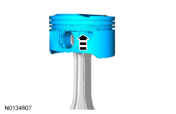
- NOTE: If the piston and/or connecting rod are being installed
new, the piston rod orientation marks and the arrow on the top of the dome
of the piston should be facing toward the front of the engine block.
Align the piston-to-connecting rod orientation marks and position the connecting rod in the piston.
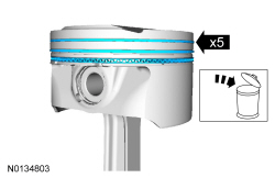
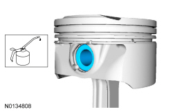
- NOTE: Lubricate the piston pin and pin bore with clean engine
oil.
Install the piston pin in the piston and connecting rod assembly.
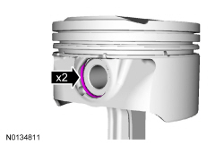
- Install the new piston pin retaining clips in the piston.
- The piston pin retaining clip gap orientation must be toward the top or dome of piston.
- NOTE: Lubricate the piston and the new piston rings with clean
engine oil.
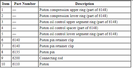
Install the piston rings on the piston.
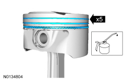
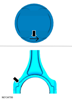
- NOTE: The piston compression upper and lower ring should be
installed with the "O" mark on the ring face pointing up toward the top of
the piston.
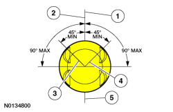
Align the piston rings on the piston.
- Center line of the piston parallel to the wrist pin bore.
- Upper compression ring gap location.
- Upper oil control segment ring gap location.
- Lower oil control segment ring gap location.
- Expander ring and lower compression ring gap location.
 Disassembly
Engine
Special Tool(s)
Material
NOTICE: During engine repair procedures, cleanliness is extremely
important. Any foreign material, including any material created while cleaning
gasket surfa ...
 Assembly
Engine
Special Tool(s)
Material
Engine Upper
Engine Front
Engine Upper - LH Cylinder Head
Engine Upper - RH Cylinder Head
Timing Drive Components
Lower Engine Block (View 1)
Lower Eng ...
Other materials:
Sunshade
The power rear sunshade covers the rear window of the vehicle.
The control is located in the center
console access bin.
Press the control to move the sunshade up or down.
Note: Do not try to manually move the sunshade.
The sunshade has a one-touch down feature. Press and release the
cont ...
Removal and Installation
Safety Belt Anchor and Pretensioner
Special Tool(s)
Removal and Installation
WARNING: All
safety belt components must be inspected and corrected as part of any collision
repair. Inspect all safety belt components as prescribed by Safety Belt
Inspection and Repair After a Collision found in ...
Specifications, Description and Operation
SPECIFICATIONS
Torque Specifications
DESCRIPTION AND OPERATION
Rear View Mirrors
Exterior, Power
Overview
Power mirrors allow the LH and RH exterior mirror glass to be positioned
electronically. The position of the power mirror glass is controlled by the
exterior mirror control switch. Selecting ...
