SPECIFICATIONS
Torque Specifications
DESCRIPTION AND OPERATION
Steering Column Switches
Overview
The steering column switches are located on or around the steering column, giving the driver the ability to control various vehicle functions and remain focused on the task of driving. Depending on vehicle options, the steering column switches consist of the following:
- Multifunction switch - mounted on the left side of the SCCM and can be serviced separately from the SCCM.
- Steering wheel switches - mounted on the front of the steering wheel and can be serviced separately from the steering wheel.
- Steering column control switch - mounted on the left side of the SCCM just below the multifunction switch and can be serviced separately from the SCCM.
- Pedal adjust switch - mounted on the left side of the SCCM just below the multifunction switch and can be serviced separately from the SCCM.
The steering column switches interface with the other modules and components on the vehicle through the SCCM.
Component Description
Multifunction Switch
The multifunction switch is a multiple position switch controlled by a lever. The multifunction switch controls the turn signals, headlamp low/high beam and headlamp dimmer/flash-to-pass, front windshield wipers and front windshield washer functions.
For additional information on the turn signals, headlamp low/high beam and headlamp dimmer/flash-to-pass, REFER to Section 417-01.
For additional information on the front windshield wipers and front windshield washers, REFER to Section 501-16.
Steering Wheel Switches
The steering wheel switches are comprised of 2 switch clusters mounted on each side of the steering wheel facing the driver. Each switch cluster contains 3 rocker switches and a 5-way directional switch pad.
The 5-way directional switch pad on the left switch cluster controls the message center display. REFER to Section 413-01.
The 3 rocker switches on the left switch cluster control the adaptive or non-adaptive cruise control. REFER to Section 419-03A or Section 419-03B.
Non-police vehicles: The 3 rocker switches on the right switch cluster controls the infotainment display. Refer to the appropriate section in Group 415 for the procedure.
Police vehicles: The 3 rocker switches on the right switch cluster are used to control the configurable auxiliary system and the infotainment display. REFER to Section 415-00A.
The 5-way directional switch pad on the right switch cluster controls the infotainment display. Refer to the appropriate section in Group 415 for the procedure.
Steering Column Control Module (SCCM)
The SCCM is attached to the steering column, behind the steering wheel. The SCCM receives inputs from the following items:
- Multifunction switch
- Pedal adjust switch
- Steering wheel rotation sensor
- Steering wheel switches
- Wiper washer switch
Using the inputs above, the SCCM controls the output directly or transmits the information as messages on either the HS-CAN or the LIN.
The SCCM also provides a "pass-through" circuit path, via the clockspring, for the following components and/or features:
- Driver air bag module
- Horn
- Steering wheel switch illumination
The SCCM monitors all of the inputs it receives and is capable of setting DTCs if a fault is detected.
Pedal Adjust Switch
The pedal adjust switch is a momentary contact switch used to adjust the position of the brake and accelerator pedals. REFER to Section 206-06.
Steering Column Control Switch
The steering column control switch is a momentary contact switch used to adjust the position of the power adjustable steering column. For additional information on the power adjustable steering column, REFER to Section 211-04.
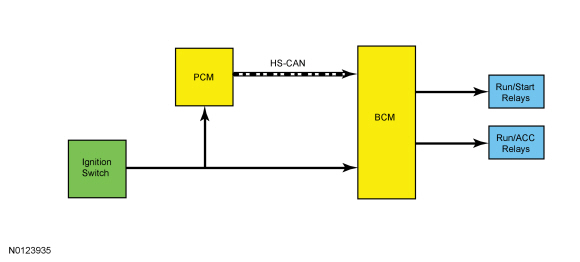
Key-Type Ignition Switch System (Without Intelligent Access)
Overview
The conventional ignition switch is controlled by the ignition lock cylinder and key. The ignition lock cylinder and ignition switch are connected mechanically, turning the lock cylinder places the switch into the desired position. The available ignition switch positions are:
- OFF
- ACC
- RUN
- START
When placed in any position other than OFF, the ignition switch provides voltage inputs to the BCM. The BCM distributes this voltage to other modules and vehicle systems through the RUN/ACC and the RUN/START relays. The microprocessor internal to the BCM broadcasts an ignition mode network message over the MS-CAN and the HS-CAN.
System Operation
System Diagram
OFF
When the ignition switch is turned to the OFF position, the BCM sends an "engine off" message to the other modules over the HS-CAN.
ACC
When the BCM receives the ACC voltage input from the ignition switch it activates the RUN/ACC bus and the RUN/ACC relay, providing ignition accessory power to the various vehicle systems and modules. The BCM also sends out the ignition mode message on the MS-CAN and the HS-CAN.
RUN
When the BCM receives the RUN voltage input from the ignition switch it activates the RUN/ACC bus, the RUN/START bus, the RUN/ACC relay and the RUN/START relay, providing ignition power to the various vehicle systems and modules. The BCM also sends out the ignition mode message on the MS-CAN and the HS-CAN.
START
When the BCM receives the START voltage input from the ignition switch it activates the RUN/START bus and the RUN/START relay, providing ignition power to the various vehicle systems and modules. The BCM also sends out the ignition mode message on the MS-CAN and the HS-CAN.
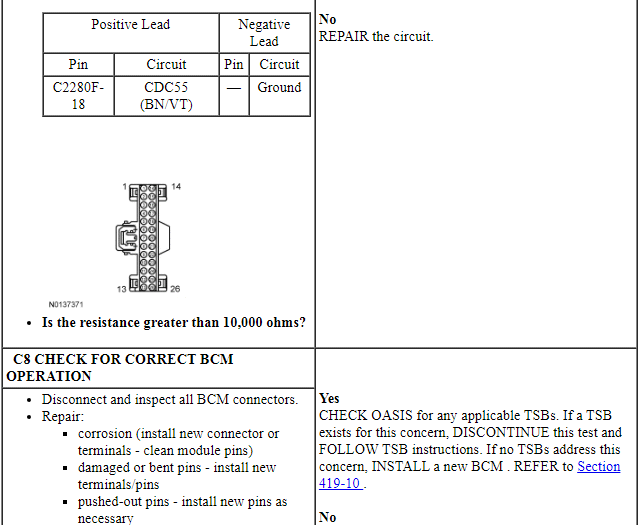
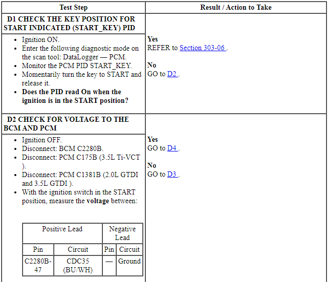
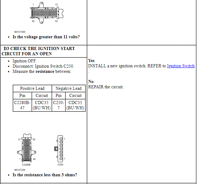
The ignition switch START circuit is also hard wired to the PCM. The PCM uses the ignition switch START input to determine when to activate the starter motor relay. REFER to Section 303-06.
Component Description
Ignition Switch
The ignition switch is a multiple position, rotary switch that is controlled by a lock cylinder and a key. The switch is hardwired to the BCM, PCM and the BSIA.
The key removal inhibit solenoid (also known as the key release interlock actuator) is an electronically controlled solenoid that prevents the ignition lock cylinder from being turned to the OFF position unless the gear selector lever is in the PARK position. The key removal inhibit solenoid is part of the ignition switch.
BCM
The BCM determines the vehicle ignition mode based on the ignition switch input. The BCM communicates the ignition mode to the other modules over the MS-CAN and the HS-CAN. The BCM monitors the ignition switch input and the ignition mode outputs, if a fault is detected in the ignition system DTCs are set by the BCM. REFER to Section 419-01B.
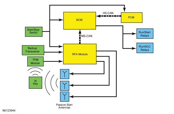
Start/Stop Ignition Switch System (With Intelligent Access)
Overview
The push-button ignition system uses the following components to achieve the 4 ignition modes (OFF, ACC, RUN and START):
- BCM
- BPP
- IA key
- RFA module
- Start/stop switch
- TPM module
To achieve any ignition mode other than OFF, the IA key must be present inside the vehicle. The driver does not need to perform any actions on or with the IA key to operate the push-button ignition system. It is sufficient that the IA key is located inside the vehicle when the start/stop switch is pressed. Pressing the start/stop switch causes the RFA module to send out a RF signal to the IA key. The IA key responds by transmitting a RF signal to the TPM module. The TPM module then sends a MS-CAN message to the RFA module that the IA key has responded. Next the RFA module sends a message over the MS-CAN to the BCM indicating that the correct IA key is present. Based on the start/stop switch and BPP switch inputs, the BCM activates the appropriate ignition mode.
Backup Transceiver
If the battery inside the IA key is weak, damaged or if excessive ambient RFI prevents communication between the RFA module and the IA key, the backup transceiver located in the center console storage compartment provides a secondary means for the RFA module to validate the IA key and authorize use of the vehicle. The backup transceiver uses close range RF identification to exchange signals with the IA key, similar to the way an encoded PATS key and transceiver operate. For information on the IA key and backup transceiver, REFER to Section 419-01C.
Push-Button Ignition System Message Center Messages
The message center provides instruction for operating the push-button ignition system. The message center also displays warnings that indicate a potential concern with the system. These messages pertain to the push-button ignition system:
- PRESS BRAKE TO START - Momentarily displays when the start/stop switch is pressed without the brake pedal being applied.
- ACCESSORY POWER ACTIVE - Displays when the vehicle is in ACC mode.
- SHIFT TO PARK - Displays when the start/stop switch is pressed to shut off the engine with the gear selector lever not in PARK.
- RESTART NOW OR KEY IS NEEDED - Displays when the start/stop switch is pressed to shut the engine off and the IA key is not detected in the vehicle.
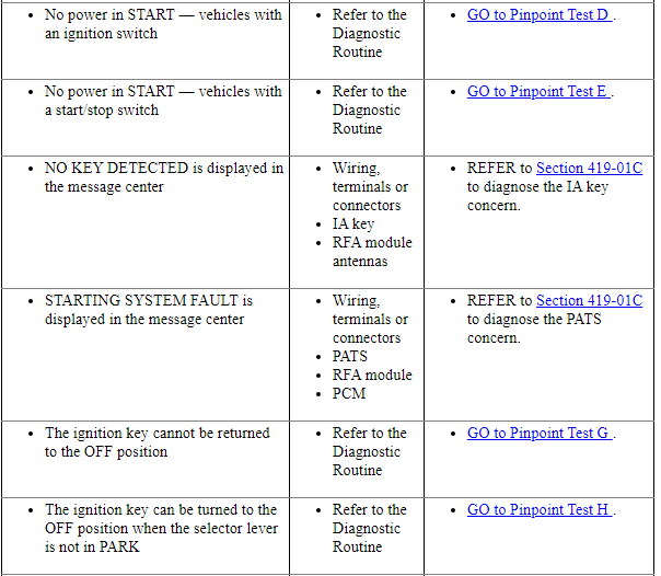
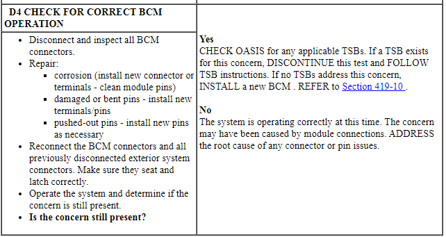
- NO KEY DETECTED - Displays if the IA key is not detected by the RFA module while attempting to start the vehicle or enter ACC or RUN mode. If this message is observed with the IA key located inside the vehicle, REFER to Section 419-01C.
- STARTING SYSTEM FAULT - Displays if the RFA module receives invalid data from the PCM during PATS authentication. If this message is observed, REFER to Symptom Chart: Passive Anti-Theft System (PATS) in Section 419-01C.
System Operation
System Diagram
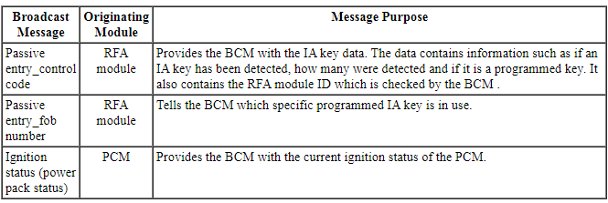
Network Message Chart
Module Network Input Messages - BCM
OFF
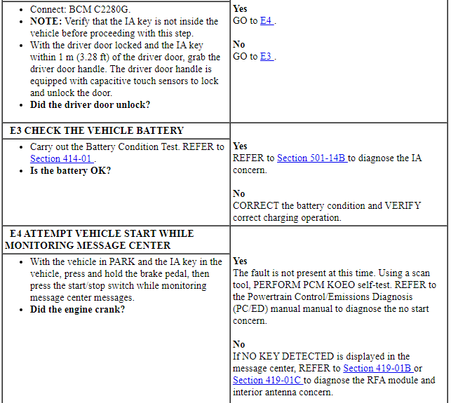
To enter OFF mode, press the start/stop button without pressing the brake pedal while the vehicle is in ACC mode, RUN mode or while the engine is running. The IA key does not have to be in the vehicle to achieve OFF mode. However, the IA key must be present to achieve any other ignition mode.
When the engine is running and any one of the vehicle doors is opened and then closed, the RFA module transmits a radio frequency to activate the IA key. If present, the IA key transmits a radio frequency signal to the TPM module. The TPM module sends a message to the RFA module indicating that the IA key is present.
If the IA key is not present, the message center displays NO KEY DETECTED to alert the driver that the IA key is not present.
If the IA key is not present while attempting to enter OFF mode, the message center displays RESTART NOW OR KEY IS NEEDED. The driver then has up to 20 seconds to restart the vehicle without an IA key being present in the vehicle.
ACC
To enter ACC mode, with the correct IA key inside the vehicle, press and release the start/stop switch one time without pressing the brake pedal. Once the BCM receives the message from the RFA module that the correct IA key is present inside the vehicle and the BCM has detected the start/stop switch input without the BPP input, the BCM activates the internal RUN/ACC bus and internal RUN/ACC relay. The BCM also sends the ignition mode message to the other modules over the MS-CAN and the HS-CAN.
Once the ignition has entered ACC mode, the message center displays, PRESS BRAKE TO START and then ACCESSORY POWER ACTIVE.
RUN
To enter RUN mode, with the correct IA key inside the vehicle, press the start/stop switch for a minimum of one second without pressing the brake pedal. Once the BCM receives the message from the RFA module that the correct IA key is present inside the vehicle and the BCM has detected the start/stop switch input without the BPP input, the BCM activates the internal RUN/ACC bus, the internal RUN/START bus, the RUN/ACC relay and the RUN/START relay. The BCM also sends the ignition mode message to the other modules over the MS-CAN and the HS-CAN.
Once the ignition has entered RUN mode, the indicator in the start/stop switch illuminates and the module controlled indicators in the IPC momentarily illuminate to prove they are functioning correctly. For IPC prove out information, REFER to Section 413-01.
Start
To enter START mode, with the correct IA key inside the vehicle, press and hold the brake pedal, then press and release the start/stop switch. Once the BCM receives the message from the RFA module that the correct key is present inside the vehicle and the BCM has detected the BPP input with the start/stop switch input, the BCM activates the internal RUN/START bus and the RUN/START relay. The BCM also sends the ignition mode message to the other modules over the MS-CAN and the HS-CAN.
The engine can be started from any ignition mode. Once the ignition has entered START mode, the indicator in the start/stop switch illuminates.
Component Description
BCM
The BCM determines the vehicle ignition mode based on the start/stop switch input, the BPP switch input and RFA module messages. The BCM communicates the ignition mode to the other modules over the MS-CAN and the HS-CAN. The BCM monitors the start/stop switch input and the ignition mode outputs. If a fault is detected in the ignition system, DTCs are set in the BCM.
For information about the BCM functions, REFER to Section 419-10.
Remote Function Actuator (RFA) Module
REFER to Section 419-01C.
Brake Pedal Position (BPP) Switch
The BPP switch (also known as the stoplamp switch) is a dual contact switch. One set of contacts is normally open and receives voltage at all times. The other set of contacts is normally closed and is connected to ground.
When the normally open contacts close, the voltage is sent to the BCM, PCM and RFA module.
When the normally closed contacts open, the ground circuit to the PCM is momentarily interrupted.
Start/Stop Switch
The start/stop switch is a momentary contact switch that is hardwired to the RFA module, BCM, and the PCM. The start/stop switch is connected to both the RFA module and BCM as a backup in case of a switch or circuit failure. In the event of a switch failure or a circuit failure between the switch and one of the modules, the module that receives the start/stop switch request transmits the request over the MS-CAN to the other module to enable ignition system operation.
The start/stop switch also has 2 LEDs, one is used for switch illumination and the other to indicate ignition mode. The ignition mode LED only illuminates when the vehicle is in RUN or START mode, it does not illuminate in ACC mode.
DIAGNOSIS AND TESTING
Steering Column Switches
DTC Charts
Diagnostic Overview
Diagnostics in this manual assume a certain skill level and knowledge of Ford-specific diagnostic practices. Refer to Diagnostic Methods in Section 100-00 for information about these practices.
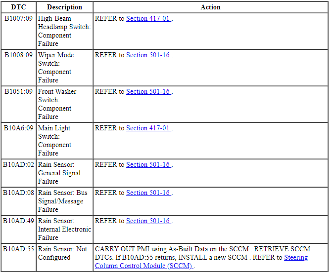
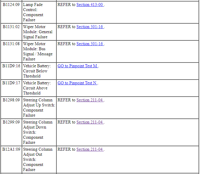
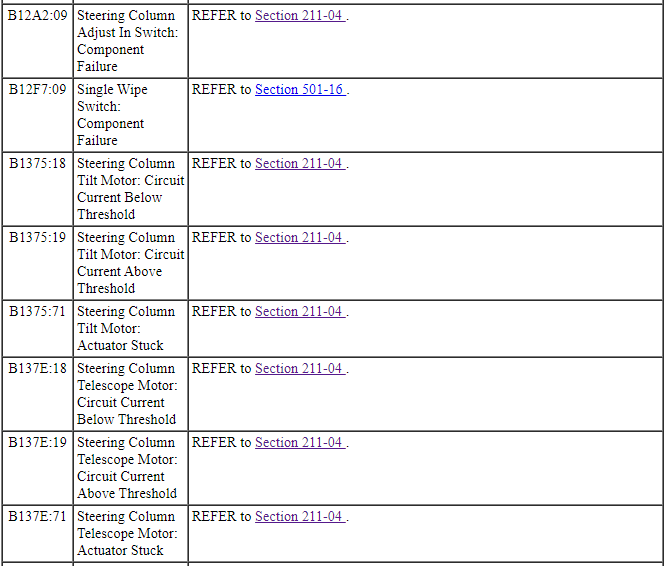
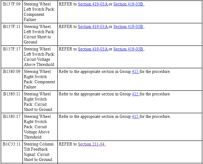
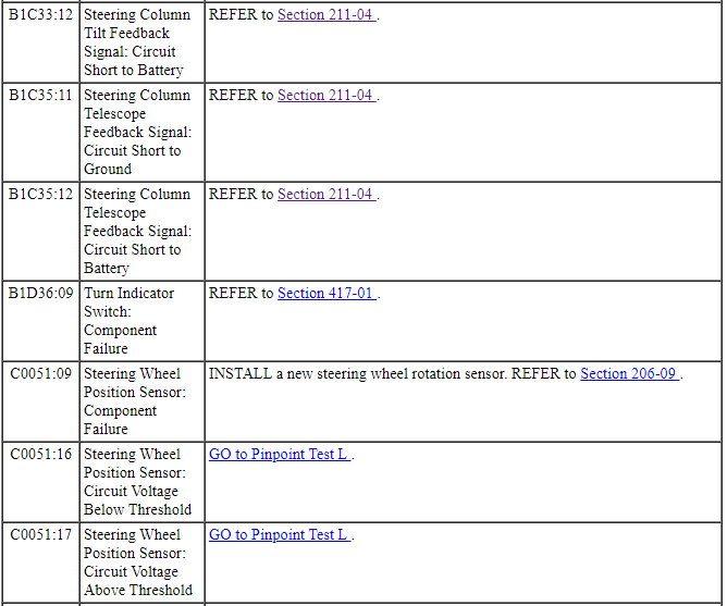
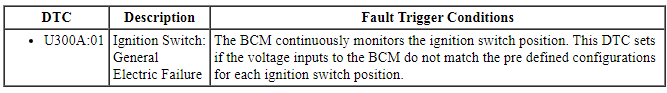
Steering Column Control Module (SCCM) DTC Chart
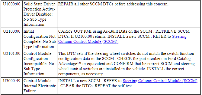
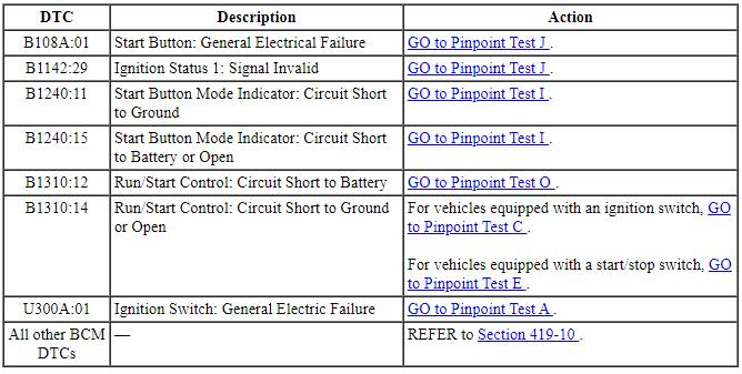
Body Control Module (BCM) DTC Chart
NOTE: Any push-button start system fault results in DTCs being stored in the Remote Function Actuator (RFA) module and BCM. Correct all RFA module DTCs prior to diagnosing the BCM DTCs listed below.
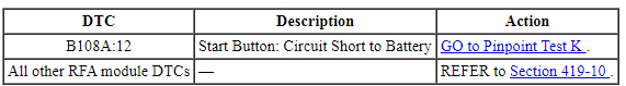
Remote Function Actuator (RFA) Module DTC Chart
Symptom Chart
Diagnostic Overview
Diagnostics in this manual assume a certain skill level and knowledge of Ford-specific diagnostic practices. Refer to Diagnostic Methods in Section 100-00 for information about these practices.
Pinpoint Tests
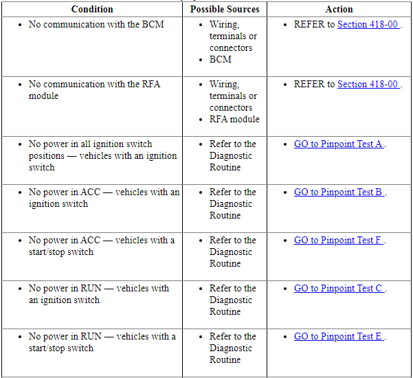
Pinpoint Test A: No Power in All Ignition Switch Positions - Vehicles with an Ignition Switch
Diagnostic Overview
Diagnostics in this manual assume a certain skill level and knowledge of Ford-specific diagnostic practices. Refer to Diagnostic Methods in Section 100-00 for information about these practices.
Refer to Wiring Diagrams Cell 13, Power Distribution/BCM for schematic and connector information.
Normal Operation and Fault Conditions
The ignition switch receives fused battery voltage from BCM fuse 26 (5A). In the ACC or RUN position, this voltage is sent to the BCM. In the START position, this voltage is sent to both the BCM and the PCM. When the ignition switch is cycled to the OFF/LOCK position from any other position, the BCM begins a monitoring cycle. The monitoring cycle checks that the voltage supplied to the BCM from the ignition switch through the RUN/ACC, RUN/START and START circuits is delivered correctly for each ignition switch position.
DTC Fault Trigger Conditions
-
Possible Sources
- Wiring, terminals or connectors
- Fuse
- Ignition switch
- BCM
-
Visual Inspection and Diagnostic Pre-checks
- Inspect for damage, corrosion or loose connections.
- Make sure the battery and battery cables are OK.
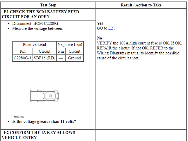
- Make sure the 100A high current fuse is OK.
- Make sure BCM fuse 26 (5A) is OK.
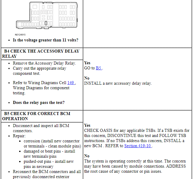
PINPOINT TEST A: NO POWER IN ALL IGNITION SWITCH POSITIONS - VEHICLES WITH AN IGNITION SWITCH
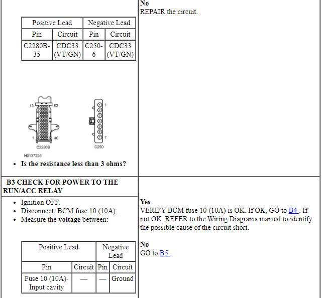
Pinpoint Test B: No Power in ACC - Vehicles With an Ignition Switch
Diagnostic Overview
Diagnostics in this manual assume a certain skill level and knowledge of Ford-specific diagnostic practices. Refer to Diagnostic Methods in Section 100-00 for information about these practices.
Refer to Wiring Diagrams Cell 13, Power Distribution/BCM for schematic and connector information.
Normal Operation and Fault Conditions
When in ACC mode, the BCM provides ground for the coil (control) side of the RUN/ACC relay located in the BCM. The RUN/ACC relay coil receives voltage from BCM fuse 10 (10A). The RUN/ACC relay is serviced with the BCM. The BCM also provides a ground circuit for the coil side of the accessory delay relay located in the BCM. The accessory delay relay can be serviced separately from the BCM.
-
Possible Sources
- Wiring, terminals or connectors
- Fuse
- RUN/ACC relay (part of the BCM )
- BCM
- Accessory delay relay
-
Visual Inspection and Diagnostic Pre-checks
- Make sure BCM fuse 10 (10A) is OK.
PINPOINT TEST B: NO POWER IN ACC - VEHICLES WITH AN IGNITION SWITCH
Pinpoint Test C: No Power in RUN - Vehicles With an Ignition Switch
Diagnostic Overview
Diagnostics in this manual assume a certain skill level and knowledge of Ford-specific diagnostic practices. Refer to Diagnostic Methods in Section 100-00 for information about these practices.
Refer to Wiring Diagrams Cell 13, Power Distribution/BCM for schematic and connector information.
Normal Operation and Fault Conditions
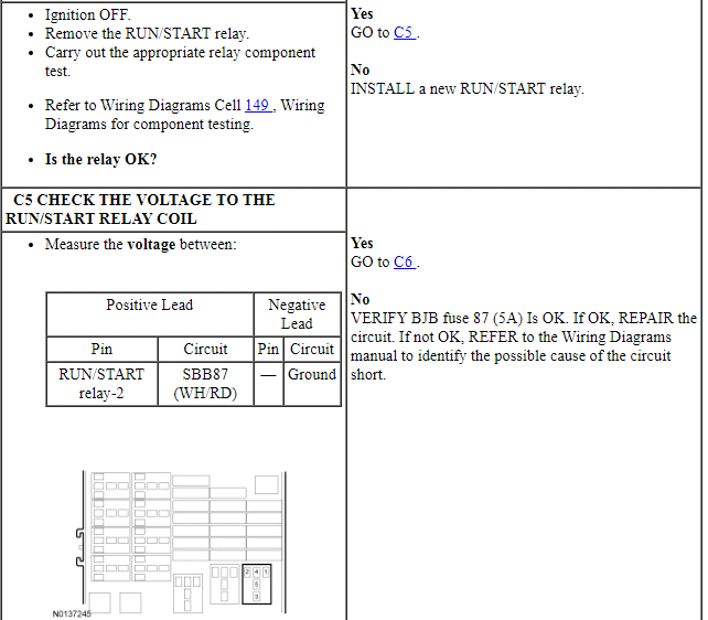
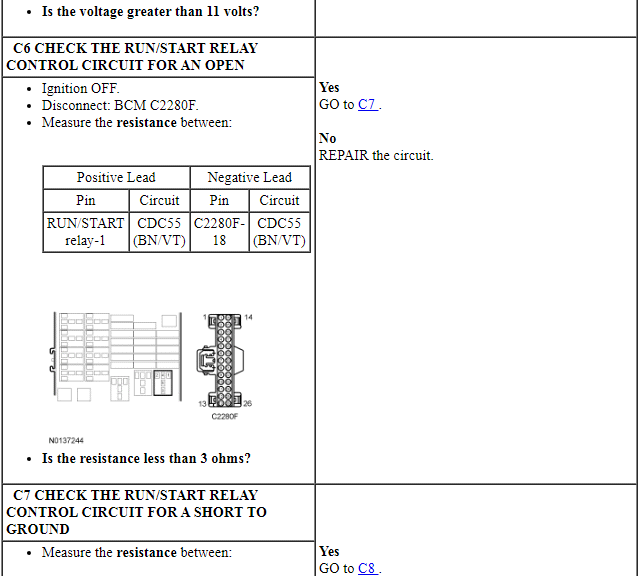
When the ignition switch is turned to the RUN position, a voltage signal is sent to the BCM. The BCM then activates the RUN/START relay and the RUN/ACC relay which distribute fused voltage to various components. The BCM uses a FET to control the RUN/START relay. The RUN/START relay receives voltage from BJB fuse 87 (5A). The RUN/ACC relay is serviced as part of the BCM.
DTC Fault Trigger Conditions
-
Possible Sources
- Wiring, terminals or connectors
- Fuse
- RUN/START relay
- Ignition switch
- BCM
-
Visual Inspection and Diagnostic Pre-checks
- Make sure BJB fuse 87 (5A) is OK.
PINPOINT TEST C: NO POWER IN RUN - VEHICLES WITH AN IGNITION SWITCH
Pinpoint Test D: No Power in START - Vehicles With an Ignition Switch
Diagnostic Overview
Diagnostics in this manual assume a certain skill level and knowledge of Ford-specific diagnostic practices. Refer to Diagnostic Methods in Section 100-00 for information about these practices.
Refer to Wiring Diagrams Cell 13, Power Distribution/BCM for schematic and connector information.
Refer to Wiring Diagrams Cell 20, Starting System for schematic and connector information.
Normal Operation and Fault Conditions
When the ignition switch is turned to the START position, a voltage signal is sent to the BCM and the PCM. The BCM sends out a voltage signal to various modules to indicate a start event and the PCM checks various inputs and HS-CAN bus messages before activating the starter motor.
-
Possible Sources
- Wiring, terminals or connectors
- Ignition switch
PINPOINT TEST D: Pinpoint Test D: NO POWER IN START - VEHICLES WITH AN IGNITION SWITCH
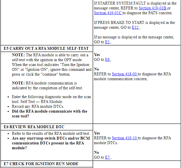
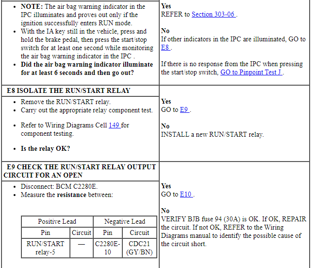
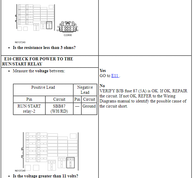
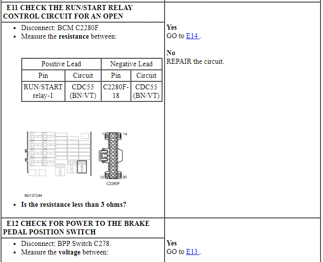
Pinpoint Test E: No Power in RUN/No Power in START - Vehicles With a Start/Stop Switch
Diagnostic Overview
Diagnostics in this manual assume a certain skill level and knowledge of Ford-specific diagnostic practices. Refer to Diagnostic Methods in Section 100-00 for information about these practices.
Refer to Wiring Diagrams Cell 13, Power Distribution/BCM for schematic and connector information.
Refer to Wiring Diagrams Cell 20, Starting System for schematic and connector information.
Normal Operation and Fault Conditions
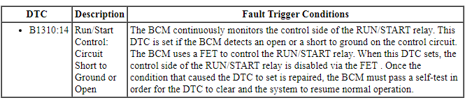
When in RUN mode, the BCM provides a ground for the coil (control) side of the RUN/START relay located in the BJB. The BCM monitors the RUN/START relay control circuit; a DTC sets if the circuit is shorted to ground or open. The start/stop switch provides a voltage input to the RFA module and PCM. The start/stop switch also provides a voltage and ground input to the BCM. The 3 modules exchange information over the HS-CAN to determine if starting the engine is authorized. If PATS authorizes the starting of the engine, the PCM supplies power and ground to the starter relay.
To place the vehicle in RUN mode, locate the IA key inside the vehicle and press the start/stop switch once, for at least one second, without applying the brake pedal.
To start the engine, locate the IA key inside the vehicle and press the start/stop switch while the brake pedal is applied.
DTC Fault Trigger Conditions
-
Possible Sources
- Battery
- Fuse(s)
- Wiring, terminals or connectors
- RUN/START relay
- Start/stop switch
- Starting system
- BPP switch (also referred to as stoplamp switch)
- RKE system
- PATS
- BCM
- RFA module or antennas
-
Visual Inspection and Diagnostic Pre-checks
- Make sure the battery, battery cables and battery terminals are free of corrosion and damage.
- Make sure 100A high current fuse is OK.
- Make sure BJB fuse 87 (5A) is OK.
- Make sure BJB fuse 59 (10A) is OK.
- Make sure BJB fuse 94 (30A) is OK.
PINPOINT TEST E: NO POWER IN RUN/NO POWER IN START - VEHICLES WITH A START/STOP SWITCH
Pinpoint Test F: No Power in ACC - Vehicles with a Start/Stop Switch
Diagnostic Overview
Diagnostics in this manual assume a certain skill level and knowledge of Ford-specific diagnostic practices. Refer to Diagnostic Methods in Section 100-00 for information about these practices.
Refer to Wiring Diagrams Cell 13, Power Distribution/BCM for schematic and connector information.
Normal Operation and Fault Conditions
When in ACC mode, the BCM provides a ground for the coil (control) side of the RUN/ACC relay located in the BCM. The RUN/ACC relay is serviced with the BCM. The BCM also provides a ground for the coil side of the accessory delay relay located in the BCM. The accessory delay relay is serviced separately from the BCM. When the vehicle is in ACC mode, ACCESSORY POWER ACTIVE will be displayed in the message center. To place the vehicle in ACC mode, locate the IA key inside the vehicle and press the start/stop switch once without applying the brake pedal.
-
Possible Sources
- Fuse(s)
- Wiring, terminals or connectors
- RUN/ACC relay (part of BCM )
- BCM
- Accessory delay relay
PINPOINT TEST F: NO POWER IN ACC - VEHICLES WITH A START/STOP SWITCH
Pinpoint Test G: The Ignition Key Cannot Be Returned to the OFF Position
Diagnostic Overview
Diagnostics in this manual assume a certain skill level and knowledge of Ford-specific diagnostic practices. Refer to Diagnostic Methods in Section 100-00 for information about these practices.
Refer to Wiring Diagrams Cell 37, Shift Interlock for schematic and connector information.
Normal Operation and Fault Conditions
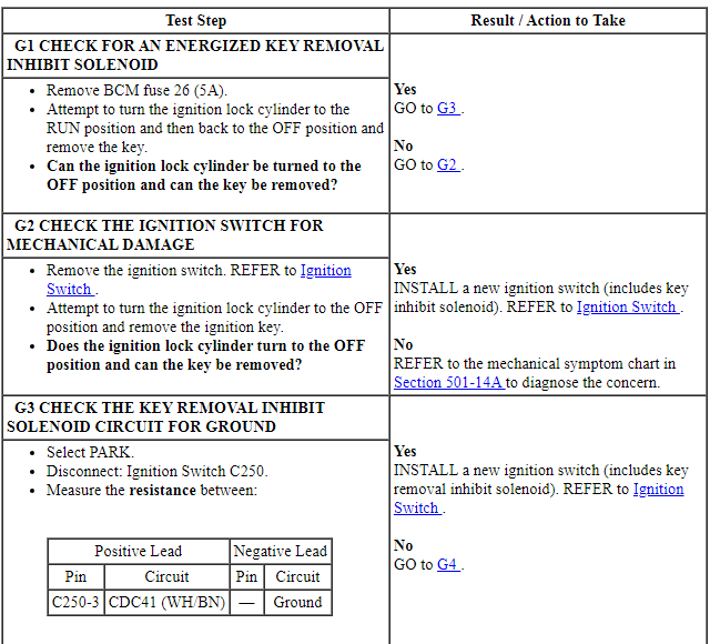
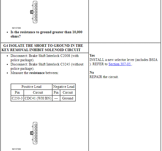
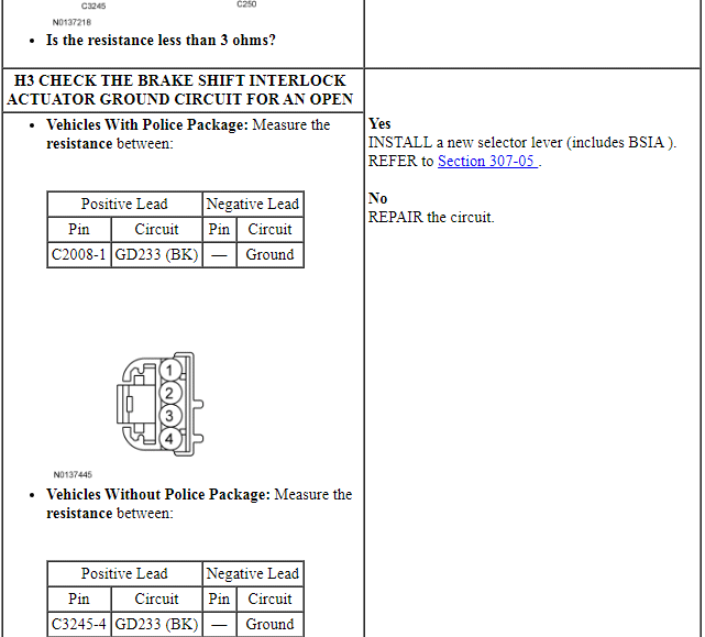
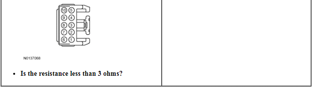
The key removal inhibit solenoid (part of the ignition switch) receives battery voltage from BCM fuse 26 (5A). When the selector lever is moved into the PARK position, the BSIA (part of the selector lever) opens, interrupting a ground circuit to the key removal inhibit solenoid. The key removal inhibit solenoid deactivates and allows the ignition lock cylinder to be turned to the OFF position and the key to be removed.
-
Possible Sources
- Wiring, terminals or connectors
- Ignition lock cylinder
- Key removal inhibit solenoid (part of the ignition switch)
- BSIA (part of the selector lever)
PINPOINT TEST G: THE IGNITION KEY CANNOT BE RETURNED TO THE OFF POSITION

Pinpoint Test H: The Ignition Key Can Be Turned to the OFF Position When the Selector Lever is Not in PARK
Diagnostic Overview
Diagnostics in this manual assume a certain skill level and knowledge of Ford-specific diagnostic practices. Refer to Diagnostic Methods in Section 100-00 for information about these practices.
Refer to Wiring Diagrams Cell 37, Shift Interlock for schematic and connector information.
Normal Operation and Fault Conditions
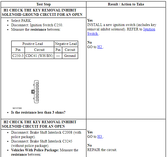
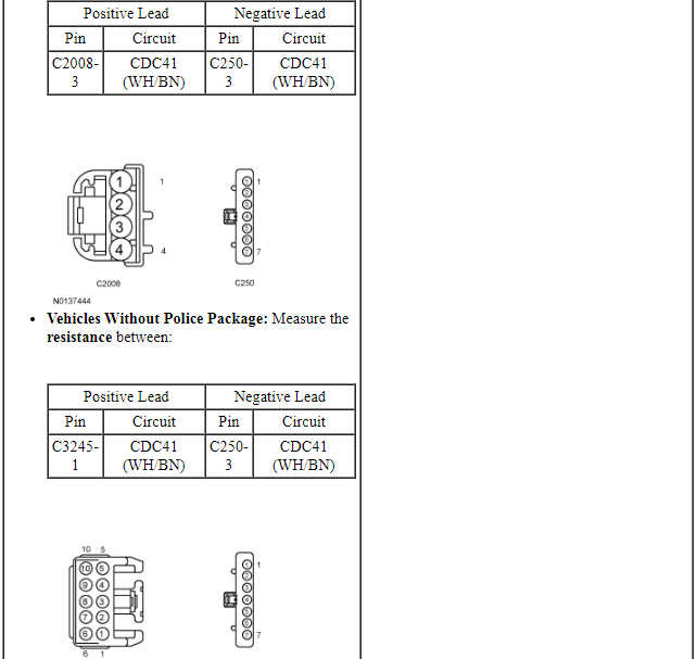
The key removal inhibit solenoid (part of the ignition switch) receives battery voltage from BCM fuse 26 (5A). When the selector lever is moved out of the PARK position, the BSIA (part of the selector lever) closes, providing a ground circuit to the key removal inhibit solenoid. The key removal inhibit solenoid activates and prevents the ignition lock cylinder from being turned to the OFF position and the key from being removed.
-
Possible Sources
- Wiring, terminals or connectors
- Key removal inhibit solenoid (part of the ignition switch)
- BSIA (part of the selector lever)
PINPOINT TEST H: THE IGNITION KEY CAN BE TURNED TO THE OFF POSITION WHEN THE SELECTOR LEVER IS NOT IN PARK
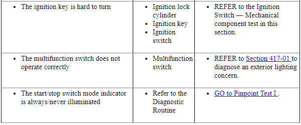
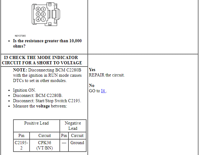
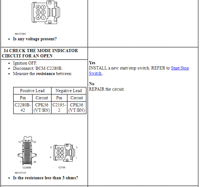
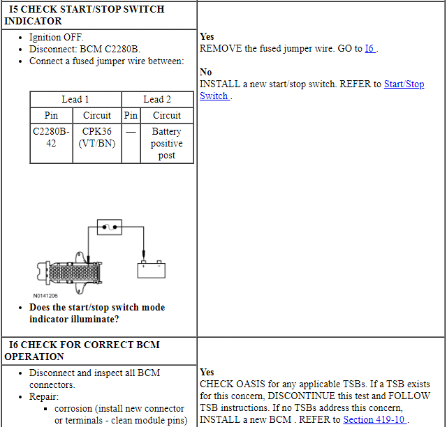
Pinpoint Test I: The Start-Stop Switch Mode Indicator is Always or Never Illuminated
Diagnostic Overview
Diagnostics in this manual assume a certain skill level and knowledge of Ford-specific diagnostic practices. Refer to Diagnostic Methods in Section 100-00 for information about these practices.
Refer to Wiring Diagrams Cell 13, Power Distribution/BCM for schematic and connector information.
Normal Operation and Fault Conditions
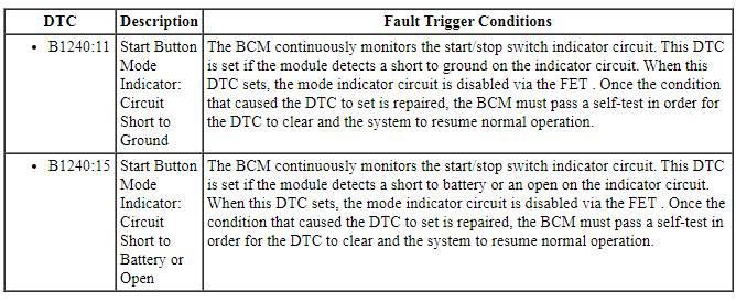
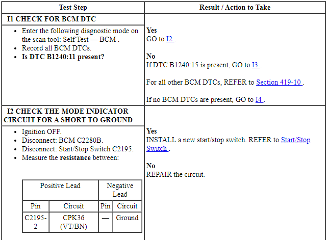
The BCM uses a FET as circuit protection for the start/stop switch indicator and as an electronic switch to turn the start/stop switch indicator On and Off. The FET receives fused battery voltage from BCM fuse 18 (10A). When the start/stop switch is pressed, a voltage and ground signal are sent to the BCM. When the vehicle enters RUN or START mode, the BCM forward biases the FET, which provides voltage to the amber LED in the start/stop switch, illuminating the word ENGINE.
DTC Fault Trigger Conditions
-
Possible Sources
- Wiring, terminals or connectors
- Start/stop switch
- BCM
PINPOINT TEST I: THE START/STOP SWITCH MODE INDICATOR IS ALWAYS/NEVER ILLUMINATED
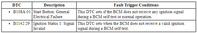
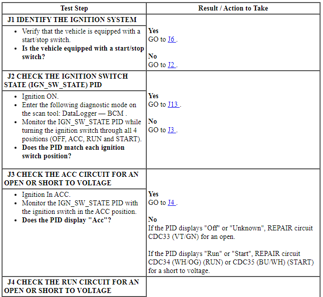
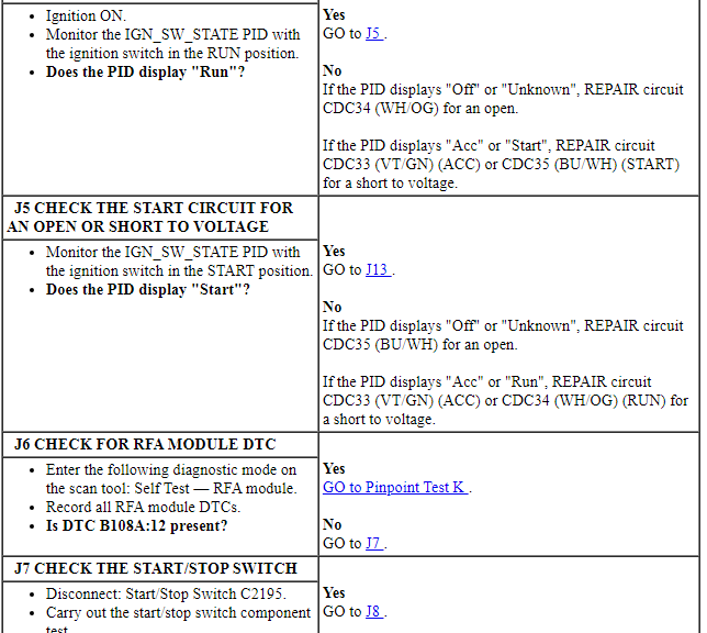
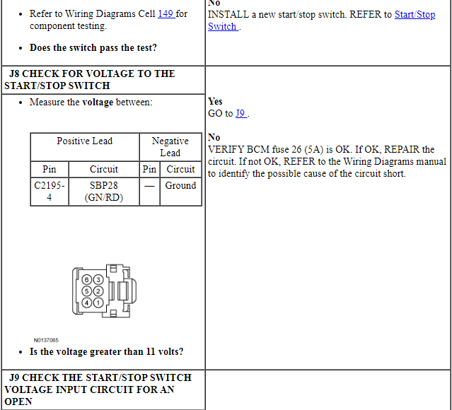
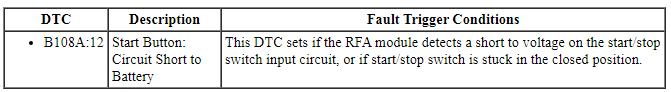
Pinpoint Test J: B108A:01 or B1142:29
Diagnostic Overview
Diagnostics in this manual assume a certain skill level and knowledge of Ford-specific diagnostic practices. Refer to Diagnostic Methods in Section 100-00 for information about these practices.
Refer to Wiring Diagrams Cell 13, Power Distribution/BCM for schematic and connector information.
Normal Operation and Fault Conditions
On vehicles equipped with a conventional ignition switch, fused battery voltage is sent to the ignition switch from BCM fuse 26 (5A). This voltage is then sent to the BCM along 1 of 3 circuits, depending on ignition switch position.
On vehicles equipped with a start/stop switch, fused battery voltage is sent to one set of contacts in the start/stop switch from BCM fuse 26 (5A). When the switch is pressed, this voltage is sent to the BCM, the RFA module and the PCM. The other set of contacts in the start/stop switch connects the BCM to ground. When the switch is pressed, the BCM detects this ground signal and takes appropriate action, based on other inputs.
DTC Fault Trigger Conditions
-
Possible Sources
- Fuse
- Wiring, terminals or connectors
- Start/stop switch
- BCM
-
Visual Inspection and Diagnostic Pre-checks
- Make sure BCM fuse 26 (5A) is OK.
PINPOINT TEST J: B108A:01 OR B1142:29
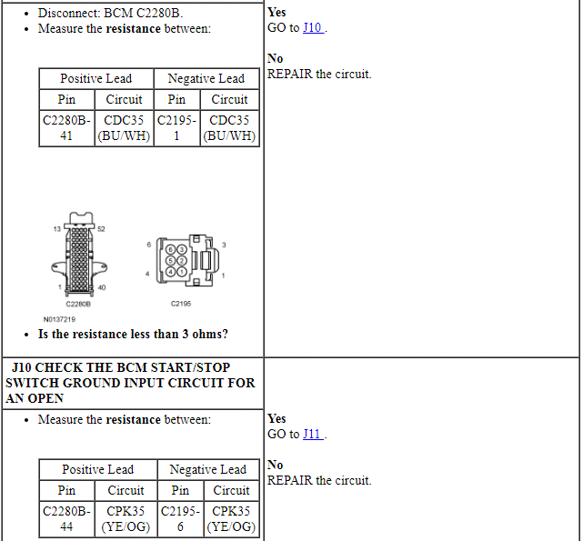
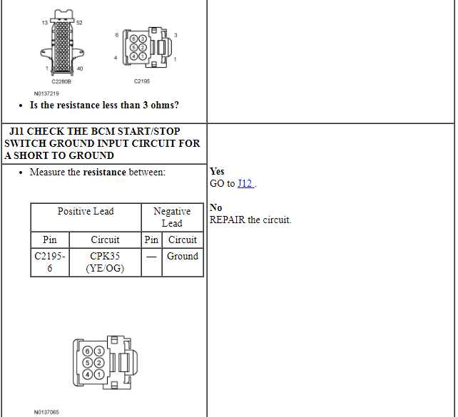
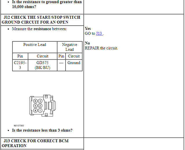

Pinpoint Test K: B108A:12
Diagnostic Overview
Diagnostics in this manual assume a certain skill level and knowledge of Ford-specific diagnostic practices. Refer to Diagnostic Methods in Section 100-00 for information about these practices.
Refer to Wiring Diagrams Cell 13, Power Distribution/BCM for schematic and connector information.
NOTE: The RFA module is only capable of setting DTC B108A:12 as a continuous memory DTC. It is possible for this DTC to be cleared and not return, even if the condition that caused it is still present. If DTC B108A:12 is retrieved, carry out this pinpoint test even if the DTC does not return.
Normal Operation and Fault Conditions
Fused battery voltage is sent to one set of contacts in the start/stop switch from BCM fuse 26 (5A). When the switch is pressed, this voltage is sent to the BCM, the RFA module and the PCM. The other set of contacts in the start/stop switch connects the BCM to ground. When the switch is pressed, the BCM detects this ground signal and takes appropriate action, based on other inputs.
DTC Fault Trigger Conditions
-
Possible Sources
- Wiring, terminals or connectors
- Start/stop switch
- PCM
- BCM
- RFA module
PINPOINT TEST K: B108A:12
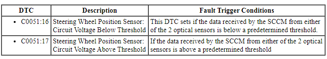
Pinpoint Test L: C0051:16 or C0051:17
Diagnostic Overview
Diagnostics in this manual assume a certain skill level and knowledge of Ford-specific diagnostic practices. Refer to Diagnostic Methods in Section 100-00 for information about these practices.
Normal Operation and Fault Conditions
The steering wheel position sensor (also known as the steering wheel rotation sensor) uses 2 optical sensors to monitor the steering wheel position relative to the center position when the ignition is in RUN. The steering wheel position sensor transmits this data to the SCCM which processes the data and transmits it on the HS-CAN. When either DTC C0051:16 or C0051:17 is set, the SCCM ignores the input from the steering wheel position sensor and transmits a fault message on the HS-CAN.
DTC Fault Trigger Conditions
-
Possible Sources
- Wiring, terminals or connectors
- Steering wheel rotation sensor
- SCCM
PINPOINT TEST L: C0051:16 OR C0051:17
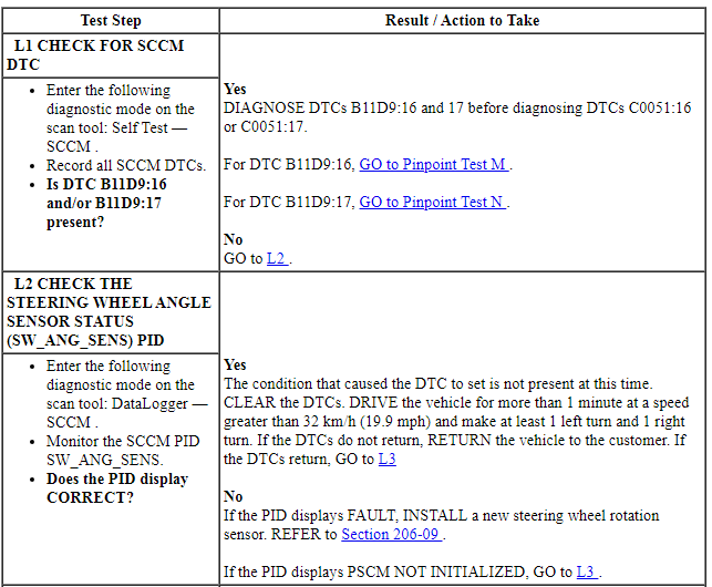
Pinpoint Test M: B11D9:16
Diagnostic Overview
Diagnostics in this manual assume a certain skill level and knowledge of Ford-specific diagnostic practices. Refer to Diagnostic Methods in Section 100-00 for information about these practices.
Refer to Wiring Diagrams Cell 42, Vehicle Dynamic Systems for schematic and connector information.
Normal Operation and Fault Conditions
The SCCM continuously monitors input voltage for correct operation. If voltage outside of defined limits is detected by the SCCM, the applicable DTC sets. DTC B11D9:16 can set if the vehicle battery has been discharged. The vehicle battery may become discharged due to excessive load(s) on the charging system from aftermarket accessories or if the vehicle has been left unattended with the accessories on.
DTC Fault Trigger Conditions
-
Possible Sources
- Battery
- Fuse(s)
- Wiring, terminals or connectors
- Charging system
- SCCM
-
Visual Inspection and Diagnostic Pre-checks
- Make sure the vehicle battery terminals and cables are free of any corrosion and other contaminates.
- Make sure the vehicle battery terminals are tightened to their correct torque specifications.
PINPOINT TEST M: B11D9:16
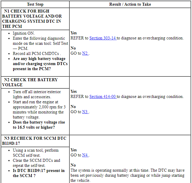
Pinpoint Test N: B11D9:17
Diagnostic Overview
Diagnostics in this manual assume a certain skill level and knowledge of Ford-specific diagnostic practices. Refer to Diagnostic Methods in Section 100-00 for information about these practices.
Refer to Wiring Diagrams Cell 13, Power Distribution/BCM for schematic and connector information.
Normal Operation and Fault Conditions
The SCCM continuously monitors input voltage for correct operation. If voltage outside of defined limits is detected by the SCCM, the applicable DTC sets. DTC B11D9:17 can set if the vehicle has been recently jump started or the vehicle battery has been recently charged.
DTC Fault Trigger Conditions
-
Possible Sources
- Wiring, terminals or connectors
- Charging system
- SCCM
PINPOINT TEST N: B11D9:17
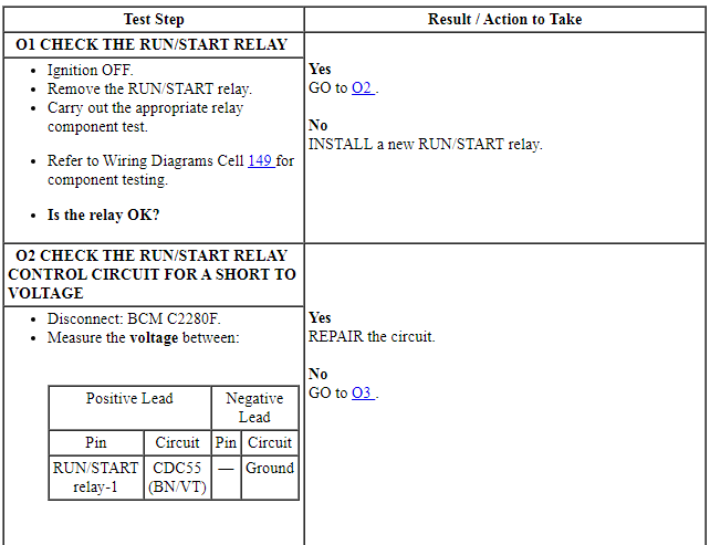
Pinpoint Test O: B1310:12
Diagnostic Overview
Diagnostics in this manual assume a certain skill level and knowledge of Ford-specific diagnostic practices. Refer to Diagnostic Methods in Section 100-00 for information about these practices.
Refer to Wiring Diagrams Cell 13, Power Distribution/BCM for schematic and connector information.
Normal Operation and Fault Conditions
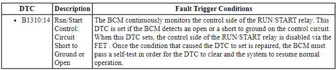
When the ignition is placed in RUN mode, the BCM provides a ground for the coil (control) side of the RUN/START relay located in the BJB. The BCM monitors the RUN/START relay control circuit and sets a DTC if the circuit is shorted to voltage.
DTC Fault Trigger Conditions
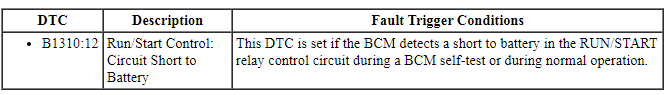
-
Possible Sources
- Wiring, terminals or connectors
- RUN/START relay
- BCM
PINPOINT TEST O: B1310:12
Component Tests
Ignition Switch - Mechanical
The following conditions can cause difficulty in operating the ignition switch and lock cylinder:
- Burrs on the lock cylinder key
- Insufficient lube on the lock cylinder
- Binding lock cylinder
- Burrs or foreign material around the rack-and-pinion actuator in the lock cylinder housing
- Insufficient lube on the actuator (Do not apply lubricant to the inside of the ignition switch.)
- Binding ignition switch
Carry out the following test to determine if the ignition switch and lock cylinder are operating correctly.
- Inspect the ignition key for any burrs, damage or incorrect cut. Have a new ignition key made as necessary.
- Turn the key to the ACC position and then the RUN position.
- If the ignition key turns to the ACC and RUN position, continue with Step 3.
- If the ignition key will not turn to the ACC and RUN position, continue with Step 4.
- NOTE: The ignition switch and lock cylinder should return from
the START position back to the RUN position without assistance.
Turn the ignition key to the START position and release the key.
- If the ignition switch and lock cylinder return from the START position back to the RUN position without assistance, the ignition switch is operating correctly at this time.
- If the ignition switch and lock cylinder do not return from the START position back to the RUN position without assistance, continue with Step 4.
- Remove the ignition lock cylinder. Refer to Section 501-14A.
- Rotate the ignition lock cylinder through all of the switch positions.
- If the lock cylinder operates correctly, install a new ignition switch. Refer to Ignition Switch.
- If the lock cylinder does not operate correctly, install a new ignition lock cylinder. Refer to Section 501-14A.
Ignition Switch - Electrical
Refer to Wiring Diagrams Cell 149 for component testing.
Start/Stop Switch - Electrical
Refer to Wiring Diagrams Cell 149 for component testing.
REMOVAL AND INSTALLATIONSteering Column Multifunction Switch
Removal and Installation
- Remove the steering column shrouds. Refer to Section 211-04.
- If equipped, remove the steering column control switch. Refer to Steering Column Control Switch.
-
- Turn steering wheel 90 degrees left.
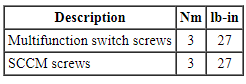
- To install, tighten to 3 Nm (27 lb-in).
- -
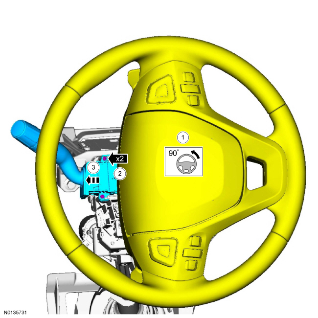
- To install, reverse the removal procedure.
Ignition Switch
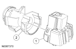
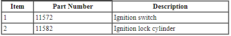
Removal and Installation
- Remove the ignition lock cylinder housing. For additional information, refer to Section 501-14A.
- Push the 2 locking tabs inward and remove the ignition switch.
- To install, reverse the removal procedure.
Start/Stop Switch
Removal and Installation
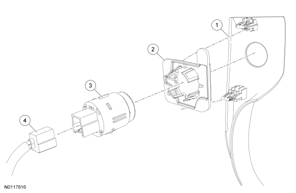
- Remove the floor console LH finish moulding in the following sequence:
- Lift up the rear of the floor console finish moulding to release the retaining clips from the floor console.
- Pull the floor console finish moulding toward the rear of the vehicle to release the retaining clips from the center instrument finish panel.
- Disconnect the start/stop switch electrical connector.
- To install, reverse the removal procedure.
- Make sure to align the retaining clips to the adjacent retaining clip holes.
Steering Wheel Switch
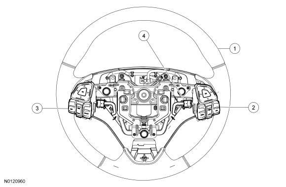
Removal and Installation
- Remove the driver air bag module. For additional information, refer to Section 501-20B.
- NOTE: Rotate the steering wheel to access the top 2 screws.
Remove the 3 steering wheel switch trim bezel screws.
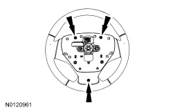
- Disconnect the steering wheel switch electrical connectors.
- Remove the steering wheel switch trim.
- Release the 4 retainer tabs on the backside of the steering wheel trim and remove the steering wheel switch.
- To install, reverse the removal procedure.
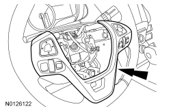
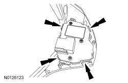
Steering Column Control Module (SCCM)
Removal and Installation
NOTE: Removal steps in this procedure may contain installation details.
- If a new SCCM is being installed, connect the scan tool and upload the module configuration information from the SCCM. For additional information on configuration, refer to PMI in Section 418-01.
- Remove the steering column shrouds and steering wheel. Refer to Section 211-04.
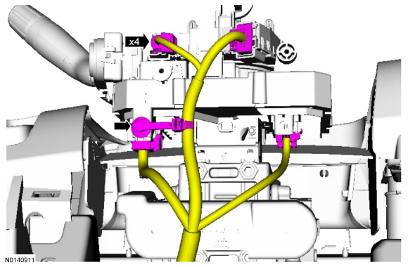
-
- To install, tighten to 3 Nm (27 lb-in).
- -
- To install, reverse the removal procedure.
- If a new SCCM was installed, it must be configured (using vehicle as-built data or module configuration information retrieved earlier in this procedure). For additional information on configuration, refer to PMI in Section 418-01.
Steering Column Control Switch
Removal and Installation
- Remove the steering column shrouds. For additional information, refer to Section 211-04.
-
- Turn steering wheel 90 degrees left.
- To install, tighten to 3 Nm (27 lb-in).
- -
- To install, reverse the removal procedure.
 Steering Column
SPECIFICATIONS
Torque Specifications
DESCRIPTION AND OPERATION
Steering Column
The steering column system consists of the following components:
Intermediate shaft
Steering column
SCCM (if eq ...
 Powertrain
...
Other materials:
Diagnosis and Testing
Engine Cooling
Special Tool(s)
Material
Principles of Operation
Engine coolant flows primarily from the engine to the radiator circuit and
back to the coolant pump. Coolant is sent from the coolant pump through the
engine block and cylinder heads. Separate circuits from the engine also feed the ...
Engine Emission Control
SPECIFICATIONS
Material
Torque Specifications
DESCRIPTION AND OPERATION
Engine Emission Control
Component Locations
2.0L GTDI
3.5L Ti-VCT and
3.7L Ti-VCT
3.5L GTDI
System Operation
Refer to the PC/ED manual
section 1 Description and Operation.
Component ...
Steering wheel controls
AUDIO CONTROL
SEEK: Press to select the next or
previous stored preset or track.
Press and hold to select the next or
previous frequency or seek through
a track.
MEDIA: Press repeatedly to scroll
through available audio modes.
MUTE: Press to silence the radio.
VOL (Volume): Press to ...
