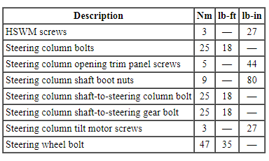
SPECIFICATIONS
Torque Specifications
DESCRIPTION AND OPERATION
Steering Column
The steering column system consists of the following components:
- Intermediate shaft
- Steering column
- SCCM (if equipped)
- Steering column switches
- Steering column tilt motor (if equipped)
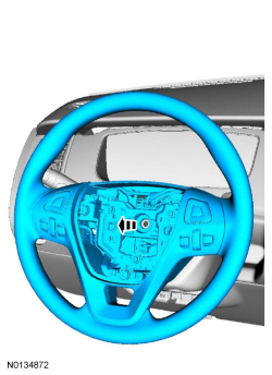
- Steering wheel
- Selector lever (if equipped)
- Upper and lower steering column shrouds
The steering column is the mechanical linkage between the steering wheel and the steering gear. The steering wheel is mounted to a shaft which passes through the center of the steering column. The shaft is centered by bearings within the steering column. The steering column shaft then connects the steering column to the steering gear. The upper and lower steering column shaft connections utilize U-joint type couplings.
Manual Adjustable Tilt/Telescope Steering Column (If Equipped)
The manual tilt/telescope function of the steering column is controlled by a mechanical lever on the underside of the steering column, which uses a cam to lock and unlock the steering column. When the lever is pulled down, the steering column can be adjusted up or down and in or out to the desired position(s). While holding the steering wheel in the desired position, pulling the lever up to its original position locks the steering column.
Power Adjustable Tilt/Telescope Steering Column (If Equipped)
The steering column is the mechanical linkage between the steering wheel and the steering gear. The steering wheel is mounted to a steering column shaft which passes through the center of the steering column. The steering column shaft is centered by bearings within the steering column. The steering column shaft utilizes U-joint type couplings in order to connect the steering column to the steering gear.
The power tilt and telescope function of the steering column is controlled by the steering column control switch, the memory SET switch or the RKE transmitter. The steering column control switch is a normally open 4-position momentary switch, located below the multifunction switch. When the steering column control switch is pressed, the steering column tilt motor moves the adjustable steering column in 4 directions:
- Forward/in (away from the driver)
- Rearward/out (toward the driver)
- Up
- Down
For steering column switch service information, refer to Section 211-05.
For selector lever service information, refer to Section 307-05.
Heated Steering Wheel
The heated steering wheel system consists of the following components:
- Heated steering wheel (with integral heating elements and temperature sensor)
- HSWM
- Heated steering wheel buttons and indicators.
The buttons and indicators for the heated steering wheel system are located in the FDIM (touchscreen) only. When activated, the HSWM activates the steering wheel heater elements, which heats the steering wheel and maintains a temperature of approximately 28-34ÂşC (82-94ÂşF) until switched off on the FDIM or the ignition is turned OFF.
The heated steering wheel can be set to activate (configured through the IPC ) when the vehicle is remotely started. During a remote start event, heated steering wheel activation depends on the ambient temperature of the vehicle and climate strategy of the HVAC module.
DIAGNOSIS AND TESTING
Steering Column
Principles of Operation
Power Adjustable Tilt/Telescope Steering Column
The power adjustable tilt/telescope steering column is controlled by the steering column control switch and 2 electric motors that are powered by the SCCM. The steering column control switch is mounted directly to the SCCM on the LH side of the steering column just below the multifunction switch, but is serviceable separately. The steering column control switch is a 4-position, momentary contact switch. When the steering column control switch is moved to any of the 4 positions, it sends a signal to the SCCM to tilt the steering column up or down or telescope the steering column forward or rearward.
The SCCM continuously monitors the steering column tilt and telescoping motors and circuits for faults. If a fault is detected, the SCCM is capable of setting DTCs.
Tilt/Telescoping Motor Sensors
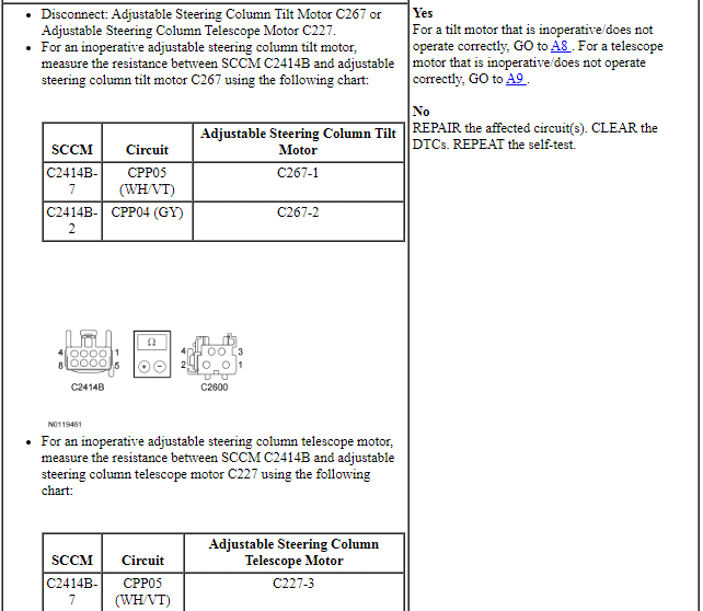
The SCCM receives digital signals from Hall-effect type rotation sensors that are integral to the tilt and telescoping motors. The SCCM uses these signals to calculate the location of the steering column in relation to the full forward/rearward and full up/down positions. The SCCM also uses these signals to store and recall memory positions, carry out the easy entry/exit operations and to make sure the tilt and telescoping motors do not stall against the steering column end of travel in the forward/rearward or up/down directions. The tilt motor is serviced separately from the steering column. The telescoping motor is not serviceable. If a new telescoping motor is needed, a new steering column must be installed.
Jog Mode
If the SCCM loses the signal from either of the motor sensors, the affected steering column motor operates in jog mode. Jog mode allows limited operation of the affected steering column motor using only the steering column control switch. When the steering column control switch is operated in jog mode, the steering column moves in the desired direction for one second, then stops. The steering column control switch must be released, then pressed again in order to move the steering column for an additional second. Jog mode is an indication that there is a tilt or telescoping motor sensor fault. If the adjustable steering column is operating in jog mode, a DTC may set in the SCCM.
Memory Position Programming and Recall
The SCCM monitors steering column position using Hall-effect sensors that are integral to the tilt and telescoping motors. When a memory position is recalled through either the memory SET switch or the RKE transmitter, the SCCM monitors the Hall-effect sensors and stops sending voltage to the steering column motors once the commanded memory position is reached. If the SCCM receives a steering column switch input during a memory position recall function, the module stops the memory recall and responds to the new steering column switch position input.
When the RKE transmitter is activated, a message is sent over the MS-CAN to the DSM. When the memory SET switch is pressed, the DSM senses continuity to ground on the switch circuit. When the DSM receives either the MS-CAN message or the ground input through the switch circuit, it sends a message over the MS-CAN to the BCM. The BCM acts as a gateway module, relaying the MS-CAN message that was received from the DSM to the SCCM over the High Speed Controller Area Network (HS-CAN). The SCCM then sends voltage over the appropriate circuit to the steering column tilt or telescoping motor to adjust the steering column position.
For additional information on setting and recalling a memory position, refer to the Owner's Literature or Memory Position Programming in Section 501-10.
Easy Entry/Exit
The easy entry/exit function moves the steering column to the full inward and upward position when the selector lever is in the PARK position and the ignition is selected off (if equipped with a push button start system) or if the ignition switch indicates the ignition key has been removed from the ignition lock cylinder (if equipped with an ignition switch). The SCCM receives an ignition status message over the HS-CAN. When the ignition status message indicates the ignition key has been removed from the lock cylinder (vehicles with an ignition switch), the SCCM commands the steering column to the full upward/forward position. For vehicles equipped with a push button start system, this occurs when the ignition status message indicates the ignition has transitioned to off. The SCCM cancels this operation if a valid input is received from the steering column control switch or memory position switch.
The SCCM records the current steering column position before powering the steering column for an easy exit operation. This recorded position returns the steering column to this position on the next easy entry operation. During easy entry operation, the steering column is returned to the position previous to the easy exit operation.
The easy entry/exit feature can be activated or deactivated using the message center. Refer to driver controls in the Owner's Literature for additional instructions for using the message center.
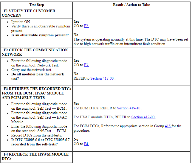
Inspection and Verification
- Verify the customer concern.
- Visually inspect for obvious signs of mechanical or electrical damage.
- Visually inspect for obstructions preventing column movement.
Visual Inspection Chart
- If an obvious cause for an observed or reported concern is found, correct the cause (if possible) before proceeding to the next step.
- NOTE: Make sure to use the latest scan tool software release.
If the cause is not visually evident, connect the scan tool to the DLC.
- NOTE: The VCM LED prove-out confirms power and
ground from the DLC are provided to the VCM.
If the scan tool does not communicate with the VCM :
- check the VCM connection to the vehicle.
- check the scan tool connection to the VCM.
- refer to Section 418-00, No Power To The Scan Tool, to diagnose no power to the scan tool.
- If the scan tool does not communicate with the vehicle:
- verify the ignition is ON.
- For vehicles with IA, the air bag warning indicator prove-out (other indicators may NOT prove ignition is ON) confirms ignition ON. If ignition does not turn ON, refer to Section 211-05 to diagnose no power in RUN.
- verify the scan tool operation with a known good vehicle.
- refer to Section 418-00, The PCM Does Not Respond To The Scan Tool, to diagnose no response from the PCM.
- verify the ignition is ON.
- Carry out the network test.
- If the scan tool responds with no communication for one or more modules, refer to Section 418-00.
- If the network test passes, retrieve and record CMDTCs.
- Clear the continuous DTCs and carry out the self test diagnostics for the SCCM.
- If the DTCs retrieved are related to the concern, go to Steering Column Control Module (SCCM) DTC Chart. For all other SCCM DTCs, refer to the Steering Column Control Module (SCCM) DTC Chart in Section 211-05.
- If no DTCs related to the concern are retrieved, GO to Symptom Chart.
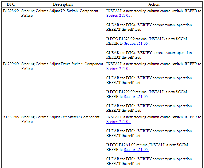
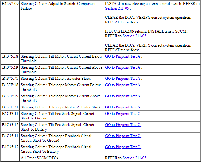
DTC Chart
NOTE: Diagnostics in this manual assume a certain skill level and knowledge of Ford-specific diagnostic practices. REFER to Diagnostic Methods in Section 100-00 for information about these practices.
Steering Column Control Module (SCCM) DTC Chart
Symptom Chart
NOTE: Diagnostics in this manual assume a certain skill level and knowledge of Ford-specific diagnostic practices. REFER to Diagnostic Methods in Section 100-00 for information about these practices.
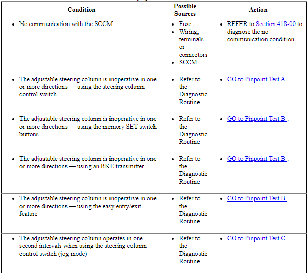
Pinpoint Tests
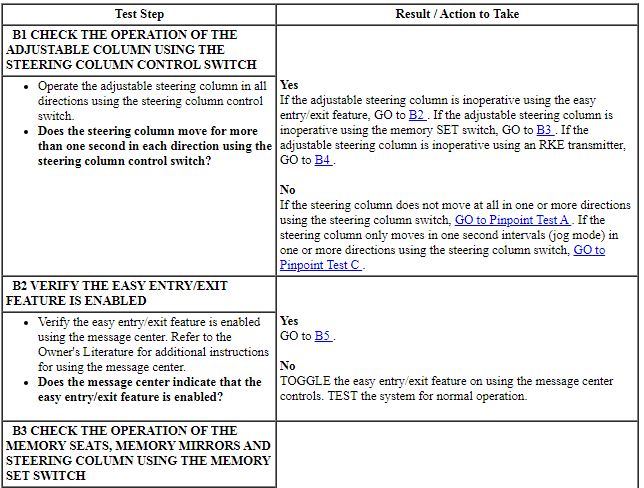
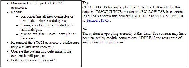
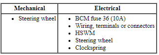
Pinpoint Test A: The Adjustable Steering Column is Inoperative in One or More Directions - Using the Steering Column Control Switch
Refer to Wiring Diagrams Cell 128, Adjustable Steering Column for schematic and connector information.
Normal Operation
When the steering column control switch (mounted directly to the SCCM ) is activated, the SCCM supplies voltage and ground to the applicable steering column tilt or telescoping motor to move the steering column to the desired position.
-
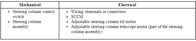
Possible Sources:
- Fuse
- Wiring, terminals or connectors
- Steering column control switch
- Adjustable steering column tilt motor
- Steering column assembly
- SCCM
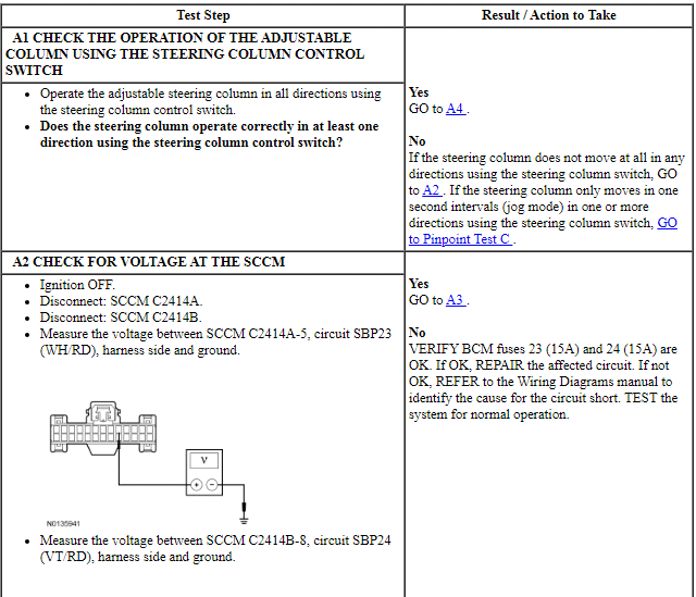
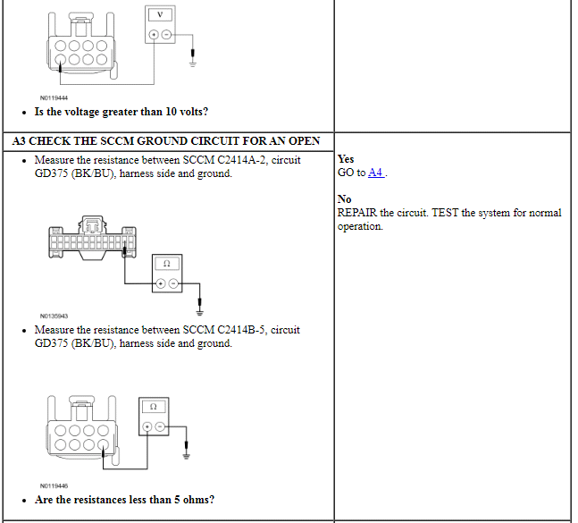
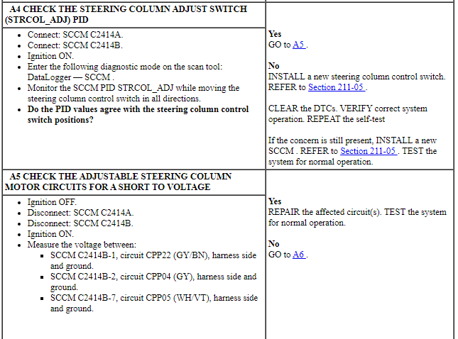
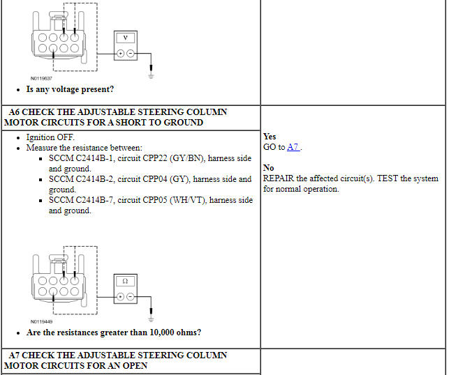
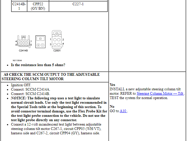
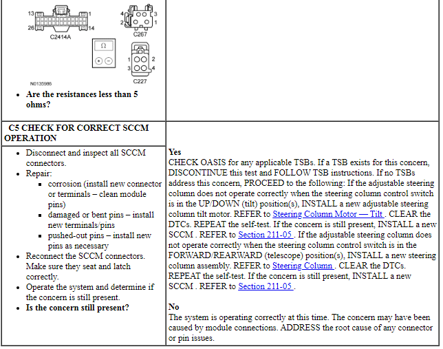
PINPOINT TEST A: THE ADJUSTABLE STEERING COLUMN IS INOPERATIVE IN ONE OR MORE DIRECTIONS - USING THE STEERING COLUMN CONTROL SWITCH
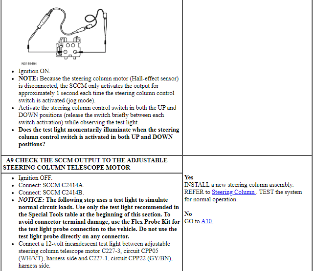
NOTICE: Use the Flex Probe Kit for all test connections to prevent damage to the wiring terminals. Do not use standard multi-meter probes.
NOTE: If the adjustable steering column only operates in one second intervals when activating the steering column control switch, GO to Pinpoint Test C.
Pinpoint Test B: The Adjustable Steering Column is Inoperative in One or More Directions - Using the Memory SET Switch Buttons/Using an RKE Transmitter/Using the Easy Entry/Exit Feature
Refer to Wiring Diagrams Cell 128, Adjustable Steering Column for schematic and connector information.
Normal Operation
When the desired memory position is selected using the memory SET switch or an RKE transmitter, the DSM communicates the desired steering column position in a message on the MS-CAN to the BCM. The BCM acts as a gateway module, relaying the message to the SCCM over the HS-CAN. The SCCM monitors the position of the adjustable steering column using Hall-effect type rotation sensors that are integral to the tilt and telescoping motors. The sensors provide a digital signal used by the SCCM to calculate the position of the steering column in relation to the full forward/rearward and full up/down positions. The SCCM uses these signals to store and recall memory positions, carry out easy entry/exit operations and to make sure the tilt and telescope motors do not stall against the steering column end of travel. If a tilt or telescope motor sensor DTC sets, the SCCM does not recall a programmed memory position or automatically position the steering column during the easy entry/exit operation. If a DTC sets for either sensor, the affected adjustable steering column motor operates in jog mode. Jog mode allows limited operation of the affected steering column motor using only the steering column control switch. When the steering column control switch is operated in jog mode, the steering column moves in the desired direction for one second, then stops. The steering column control switch must be released, then pressed again in order to move the steering column for an additional second.
-
Possible Sources:
- Entry/exit feature is disabled in the message center
- Wiring, terminals or connectors
- Memory SET switch
- RKE transmitter
- DSM
- BCM
- SCCM
PINPOINT TEST B: THE ADJUSTABLE STEERING COLUMN IS INOPERATIVE IN ONE OR MORE DIRECTIONS - USING THE MEMORY SET SWITCH BUTTONS/USING AN RKE TRANSMITTER/USING THE EASY ENTRY/EXIT FEATURE
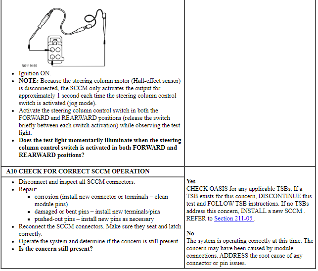
NOTICE: Use the Flex Probe Kit for all test connections to prevent damage to the wiring terminals. Do not use standard multi-meter probes.
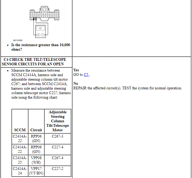
Pinpoint Test C: The Adjustable Steering Column Operates in One Second Intervals When Using the Steering Column Control Switch (Jog Mode)
Refer to Wiring Diagrams Cell 128, Adjustable Steering Column for schematic and connector information.
Normal Operation
The SCCM monitors the position of the adjustable steering column using of Hall-effect type rotation sensors that are integral to the tilt and telescoping motors. The adjustable steering column tilt motor is serviced separately from the steering column. The adjustable steering column telescope motor is not serviceable. If a new adjustable steering column telescope motor sensor is needed, install a new steering column assembly.
The SCCM sends a reference voltage along the sensor feed circuit through the Hall-effect sensor and back to the SCCM through a shared signal return circuit. The sensors provide a digital signal used by the SCCM to calculate the position of the steering column in relation to the full forward/rearward and full up/down positions. The SCCM uses this signal to store and recall memory positions, to carry out the easy entry/exit operations and to make sure the adjustable steering column tilt and telescope motors do not stall against the steering column end of travel.
If an adjustable steering column tilt or telescope motor sensor DTC sets (or if either of the sensor circuits become open), the SCCM does not recall a programmed memory position or automatically position the steering column during the easy entry/exit operations. The affected steering column motor operates in jog mode. Jog mode allows limited operation of the affected steering column motor using only the steering column control switch. When the steering column control switch is operated in jog mode, the steering column moves in the desired direction for one second, then stops regardless of the length of time the switch is actually activated. The steering column control switch must be released, then activated again in order to move the steering column for an additional second.
-
Possible Sources:
- Wiring, terminals or connectors
- Adjustable steering column tilt motor
- Steering column assembly
- SCCM
PINPOINT TEST C: THE ADJUSTABLE STEERING COLUMN OPERATES IN ONE SECOND INTERVALS WHEN USING THE STEERING COLUMN CONTROL SWITCH (JOG MODE)
NOTICE: Use the Flex Probe Kit for all test connections to prevent damage to the wiring terminals. Do not use standard multi-meter probes.
Heated Steering Wheel
Principles of Operation
Heated Steering Wheel System Operation
When a heated steering wheel request is received, the HSWM applies voltage and ground to the steering wheel heating element (integral to the steering wheel). The steering wheel is heated to a temperature of approximately 28-34ÂşC (82-94ÂşF) and is maintained by the HSWM using a temperature sensor (integral to the steering wheel). The HSWM supplies a reference voltage and ground to the temperature sensor and monitors the voltage drop for controlling current flow to the heating element. The HSWM is designed to remain on, heating the steering wheel and maintaining temperature until switched OFF on the FDIM or the ignition switch is turned OFF.
On all vehicles, slow heating between the 10 o'clock and 2 o'clock steering wheel hand positions is considered normal. On vehicles equipped with wood inserts in the steering wheel, there is no heating elements located under the inserts.
Heated Steering Wheel System Network Communication
The controls and indicators for the heated steering wheel system are in are located in the FDIM (touch screen) only. The FDIM does not communicate on any network and is connected directly to the APIM.
When the FDIM controls are used, the APIM sends a heated steering wheel request message to the HSWM using the following message path:
- The APIM sends the request over the I-CAN to the FCIM.
- The FCIM sends the request over the I-CAN to the IPC module.
- The IPC module then sends the request to the BCM over the HS-CAN.
- Lastly, the BCM sends the requests to the HSWM over the MS-CAN.
The messaging path is followed in reverse for status updates that need to be sent from the HSWM to the APIM.
Remote Start System Behavior
When the remote start feature is used, the heated steering wheel system may be configured, through the message center, to be activated by the HVAC module based on outside air temperature. During remote start, the outside air temperature is continually evaluated by the HVAC system and the heated steering wheel system activation changes if the outside air changes from cold to moderate or warm temperatures or back from moderate or warm to cold temperatures.
For cold ambient air temperatures (below 10ÂşC (50ÂşF) ) the heated steering wheel activates if the steering wheel is set to Auto in the IPC message center.
For moderate and warm ambient air temperatures (above 10ÂşC (50ÂşF) ) the heated steering wheel does not activate.
FET Protection
A FET is a type of transistor, that used with module software, monitors and controls current flow on module outputs. For information on FET protection, refer to Section 419-10.
Inspection and Verification
- Verify the customer concern.
- Visually inspect for obvious signs of mechanical or electrical damage.
Visual Inspection Chart
- If an obvious cause for an observed or reported concern is found, correct the cause (if possible) before proceeding to the next step.
- NOTE: Make sure to use the latest scan tool software release.
If the cause is not visually evident, connect the scan tool to the DLC.
- NOTE: The VCM LED prove-out confirms power and
ground from the DLC are provided to the VCM.
If the scan tool does not communicate with the VCM :
- check the VCM connection to the vehicle.
- check the scan tool connection to the VCM.
- refer to Section 418-00, No Power To The Scan Tool, to diagnose no power to the scan tool.
- If the scan tool does not communicate with the vehicle:
- verify the ignition is ON.
- For vehicles with IA, the air bag warning indicator prove-out (other indicators may NOT prove ignition is ON) confirms ignition ON. If ignition does not turn ON, refer to Section 211-05 to diagnose no power in RUN.
- verify the scan tool operation with a known good vehicle.
- refer to Section 418-00 to diagnose no response from the PCM.
- verify the ignition is ON.
- Carry out the network test.
- If the scan tool responds with no communication from one or more modules, refer to Section 418-00.
- If the network test passes, retrieve and record the CMDTCs.
- Clear the CMDTCs and carry out the self-test diagnostics from the HSWM.
- If the HSWM DTCs retrieved are related to the concern, go to the Heated Steering Wheel Module (HSWM) DTC Chart. For all other DTCs, refer to Section 419-10.
- If no DTCs related to the concern are retrieved, GO to Symptom Chart.
DTC Charts
Heated Steering Wheel Module (HSWM) DTC Chart
NOTE: Diagnostics in this manual assume a certain skill level and knowledge of Ford-specific diagnostic practices. REFER to Diagnostic Methods in Section 100-00 for information about these practices.
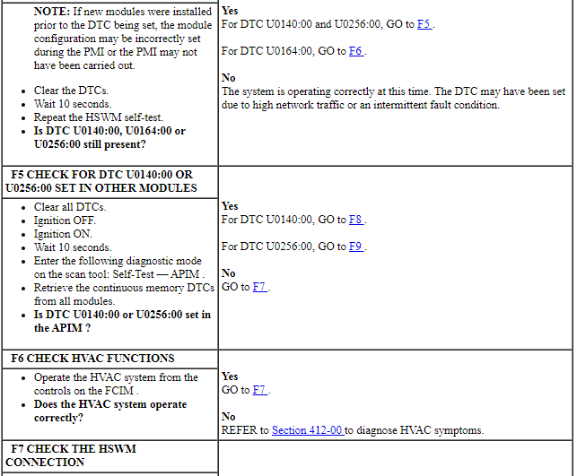
NOTE: Network DTCs (U-codes) are often a result of intermittent concerns such as damaged wiring or low battery voltage occurrences. Additionally, vehicle repair procedures such as module reprogramming often set network DTCs. Replacing a module to resolve a network DTC is unlikely to resolve the concern. To prevent repeat network DTC concerns, inspect all network wiring, especially connectors. Test the vehicle battery, refer to Section 414-01.
Symptom Chart
NOTE: Diagnostics in this manual assume a certain skill level and knowledge of Ford-specific diagnostic practices. REFER to Diagnostic Methods in Section 100-00 for information about these practices.
Pinpoint Tests
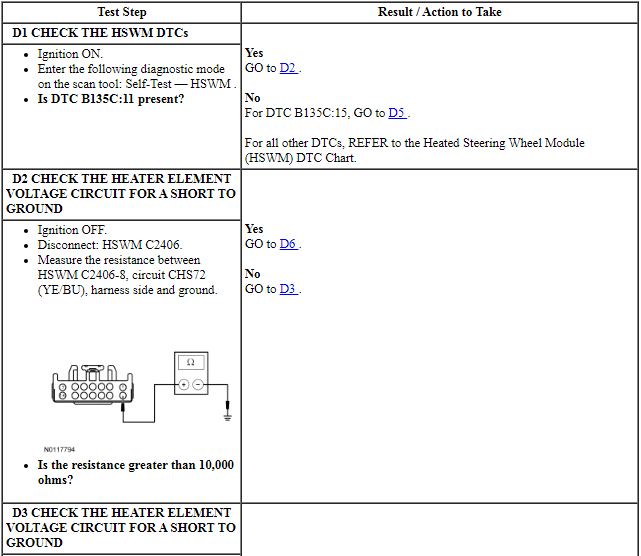
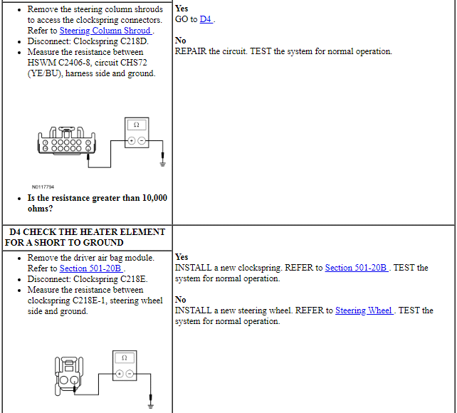
Pinpoint Test D: DTC B135C:11 or B135C:15
Refer to Wiring Diagrams Cell 128, Adjustable Steering Column for schematic and connector information.
Normal Operation
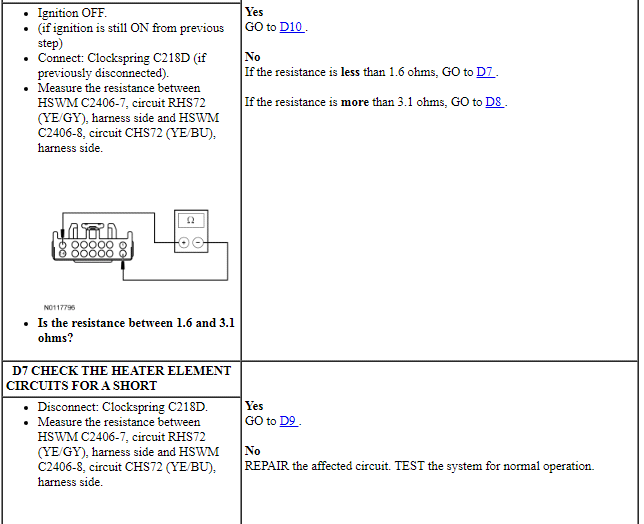
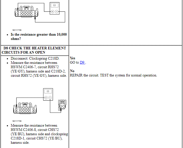
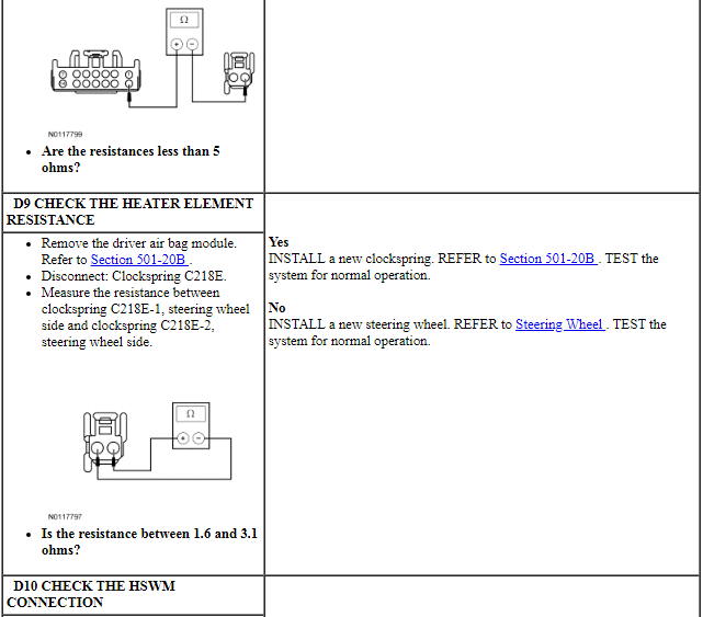
When steering wheel heat is requested, the HSWM applies voltage and ground to the steering wheel heating element (integral to the steering wheel). The steering wheel heating element will draw between 1 and 10A of current depending on steering wheel temperature. The steering wheel contains 3 heating elements wired in parallel and has a resistance of 1.6-2.6 ohms. If the steering wheel is equipped with wood inserts, the steering wheel contains 2 heating elements wired in parallel and has a resistance of 2.1-3.1 ohms. The heated steering wheel temperature is maintained by the HSWM using a sensor in the steering wheel (integral to the steering wheel). The HSWM is designed to remain on, heating the steering wheel and maintaining temperature until switched OFF on the FDIM or the ignition is turned OFF.
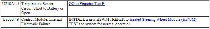
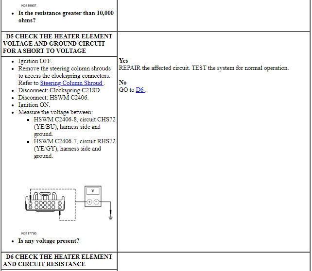
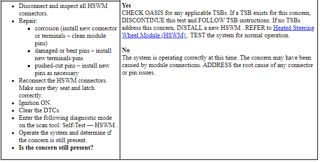
- DTC B135C:11 (Heater Element: Circuit Short to Ground) - This DTC will only set when the heated steering wheel is commanded on. The module senses current greater than 10A on the steering wheel heating element output circuit for greater than 80ms, indicating a short to ground, this DTC sets. This DTC also sets when the steering wheel heating element output FET in the module has a thermal failure. The steering wheel heating element output will be disabled until the ignition is cycled.
- DTC B135C:15 (Heater Element: Circuit Short to Battery or Open) - This DTC will only set when the heated steering wheel is commanded on. The module senses current less than 1A on the steering wheel heating element output circuit for more than 80ms, indicating a short to voltage or an open circuit or heating element. The steering wheel heating element output will be disabled until the ignition is cycled.
-
Possible Sources:
- Wiring, terminals or connectors
- Steering wheel
- Clockspring
- HSWM
PINPOINT TEST D: DTC B135C:11 OR B135C:15
Pinpoint Test E: DTC U210A:11 or U210A:15
Refer to Wiring Diagrams Cell 128, Adjustable Steering Column for schematic and connector information.
Normal Operation
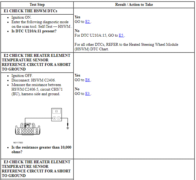
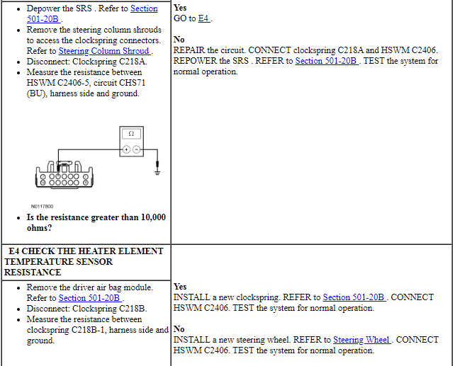
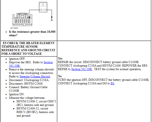
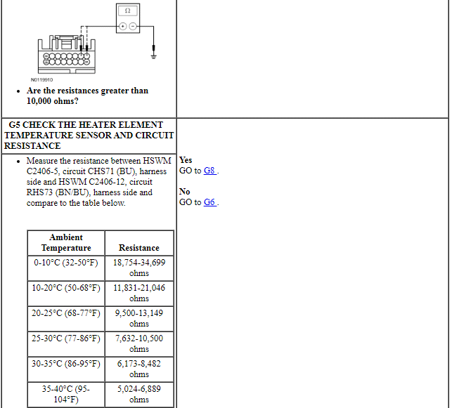
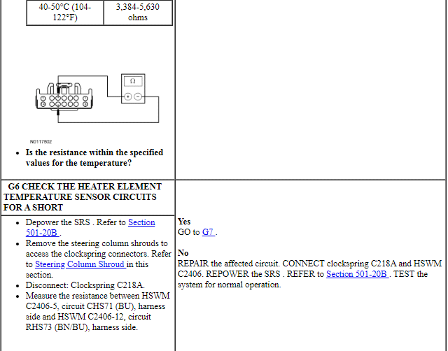
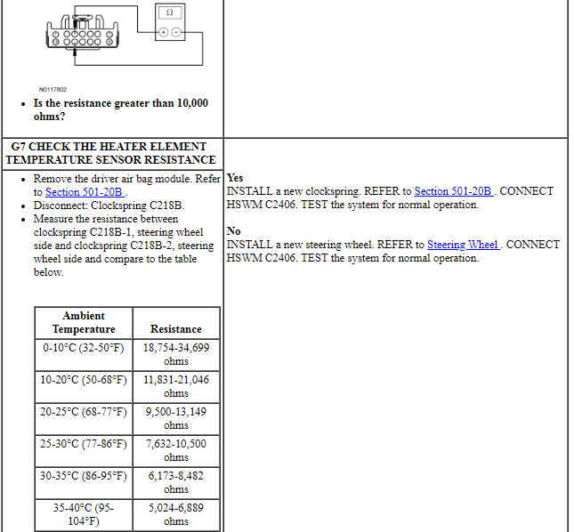
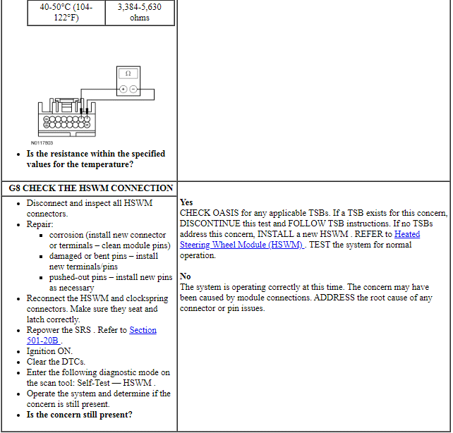
When steering wheel heat is requested, the heated steering wheel temperature is maintained by the HSWM using a sensor in the steering wheel (integral to the steering wheel). The resistance of the sensor rises as the temperature falls and the resistance falls as the temperature rises. The resistance can vary from 3,384 ohms at 50ÂşC (122ÂşF) to 34,699 ohms at 0ÂşC (32ÂşF). The HSWM supplies a reference voltage and ground to the temperature sensor and monitors the voltage drop from the temperature sensor for controlling current flow to the heating element. The HSWM is designed to remain on, heating the steering wheel and maintaining temperature until switched OFF on the FDIM or the ignition is turned OFF.
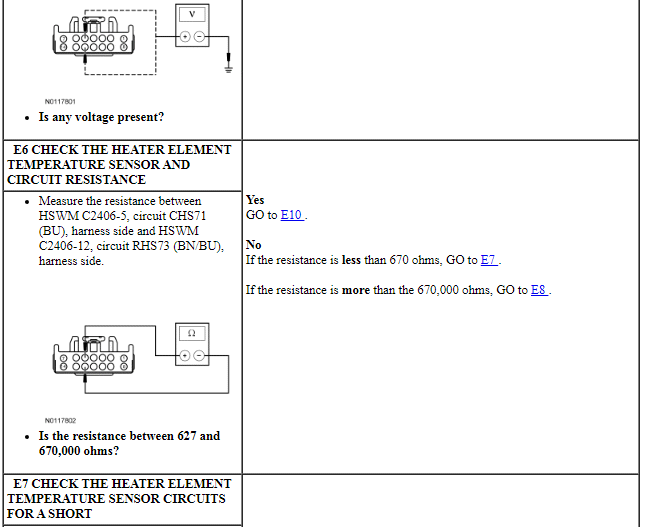
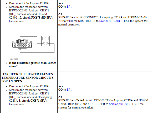
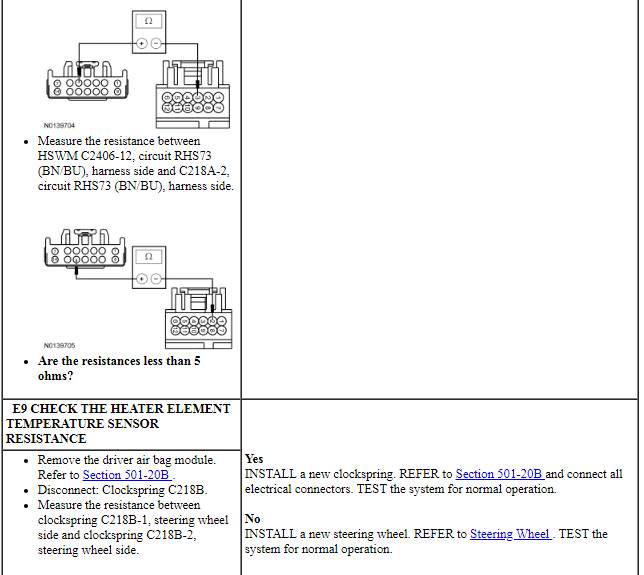
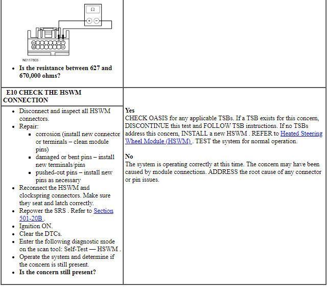
- DTC U210A:11 (Temperature Sensor: Circuit Short to Ground) - This DTC will only set when the heated steering wheel is commanded on. The module reads a resistance value less than 627 ohms on the heating element temperature sensor input circuit for greater than 640ms, indicating a short to ground. The steering wheel heating element output will be disabled until the ignition is cycled.
- DTC U210A:15 (Temperature Sensor: Circuit Short to Battery or Open) - This DTC will only set when the heated steering wheel is commanded on. The module reads a resistance value greater than 670,000 ohms on the heating element temperature sensor reference circuit for greater than 10 minutes, indicating a short to voltage or an open circuit or heating element temperature sensor. The steering wheel heating element output will be disabled until the ignition is cycled.
-
Possible Sources:
- Wiring, terminals or connectors
- Steering wheel
- Clockspring
- HSWM
PINPOINT TEST E: DTC U210A:11 OR U210A:15
Pinpoint Test F: DTC U0140:00, U0164:00 and U0256:00
-
Normal Operation
- DTC U0140:00 (Lost Communication With Body Control Module: No Sub-Type Information) - sets in continuous memory in the HSWM if data messages received from the BCM over the MS-CAN are missing for 5 seconds or more. For a complete list of all network messages, refer to Section 418-00.
- DTC U0164:00 (Lost Communication With HVAC Control Module: No Sub Type Information) - sets in continuous memory in the HSWM if data messages received from the HVAC module over the MS-CAN are missing for 5 seconds or more. For a complete list of all network messages, refer to Section 418-00.
- DTC U0256:00 (Lost Communication With Front Controls Interface Module "A": No Sub Type Information) - sets in continuous memory in the HSWM if data messages received from the FCIM over the MS-CAN are missing for 5 seconds or more. For a complete list of all network messages, refer to Section 418-00.
-
Possible Sources:
- BCM
- HVAC module
- FCIM
PINPOINT TEST F: DTC U0140:00, U0164:00 AND U0256:00
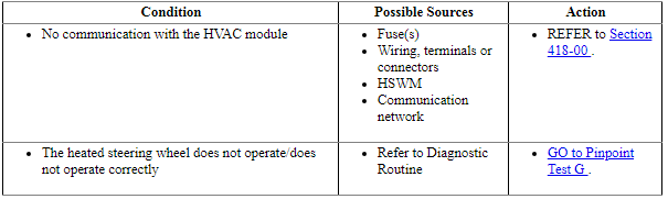
Pinpoint Test G: The Heated Steering Wheel Does Not Operate/Does Not Operate Correctly
Refer to Wiring Diagrams Cell 128, Adjustable Steering Column for schematic and connector information.
Normal Operation
When steering wheel heat is requested, the heated steering wheel temperature is maintained by the HSWM using a sensor in the steering wheel (integral to the steering wheel). The resistance of the sensor rises as the temperature falls and the resistance falls as the temperature rises. The resistance can vary from 3,384 ohms at 50ÂşC (122ÂşF) to 34,699 ohms at 0ÂşC (32ÂşF). The HSWM supplies a reference voltage and ground to the temperature sensor and monitors the voltage drop from the temperature sensor for controlling current flow to the heating element. The HSWM is designed to remain on, heating the steering wheel and maintaining temperature until switched OFF on the FDIM or the ignition is turned OFF.
NOTE: On all vehicles, slow heating between the 10 o'clock and 2 o'clock steering wheel hand positions is considered normal. On vehicles equipped with wood inserts in the steering wheel, there is no heating elements located under the inserts.
-
Possible Sources:
- Wiring, terminals or connectors
- Steering wheel
- Clockspring
- HSWM
PINPOINT TEST G: THE HEATED STEERING WHEEL DOES NOT OPERATE/DOES NOT OPERATE CORRECTLY
GENERAL PROCEDURES
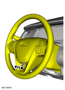
Steering Wheel Wrap Bonding
Material
- NOTE: If re-adhering leather to the front side of the steering
wheel only, it will not be necessary to remove the steering wheel. Steering
wheel removal is necessary only when repairing loose leather on the backside
of the steering wheel.
If necessary remove the steering wheel. For additional information, refer to Steering Wheel in this section.
- Position the loose leather out of the way.
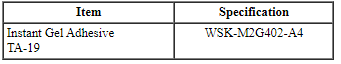
- Apply the specificed adhesive evenly over the wheel spoke.
- Position the loose leather back into the original position.
- NOTE: The adhesive should be completely set after 5 minutes. Do
not pull on the repair area.
Smooth the leather and tuck in for neat appearance.
- Apply pressure (for at least 30 seconds) until the leather is bonded to the wheel spoke.
- If removed, Install the steering wheel. For additional information, refer to Steering Wheel in this section.
REMOVAL AND INSTALLATION
Steering Wheel
Removal and Installation
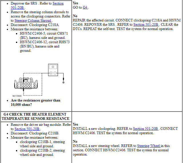
NOTICE: Do not allow the clockspring to rotate while the steering wheel is disconnected or damage to the clockspring may result. If there is evidence that the clockspring has rotated, the clockspring must be recentered. Refer to Section 501-20B.
NOTE: Removal steps in this procedure may contain installation details.
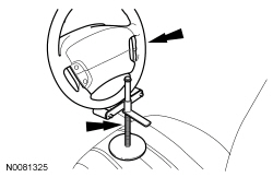
- Remove the driver air bag module. Refer to Section 501-20B.
-
- Discard the specified component. Follow local disposal regulations.
- To install, tighten the new bolt to 47 Nm (35 lb-ft).
- -
- Discard the specified component. Follow local disposal regulations.
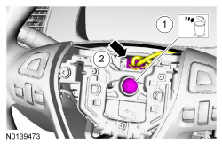
- Apply tape to specified component or area.
- To install, reverse the removal procedure.
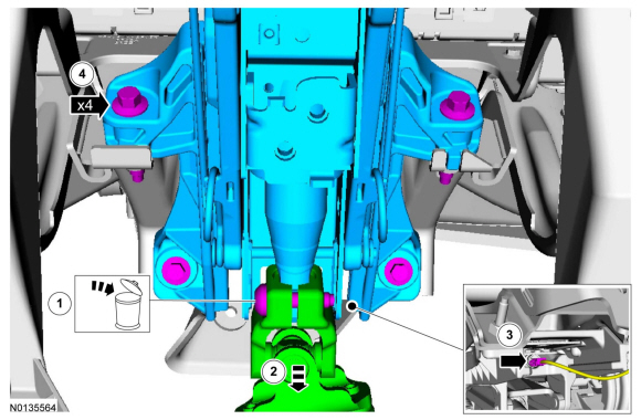
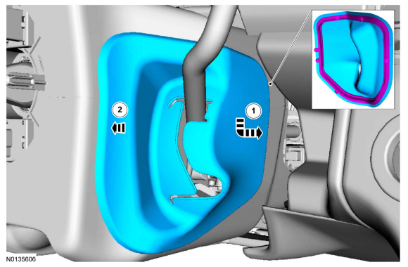
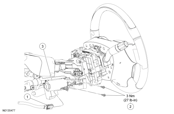
Steering Column
Removal and Installation
NOTICE: Do not allow the steering wheel to rotate while the steering column shaft is disconnected or damage to the clockspring may result. If there is evidence that the steering wheel has rotated, the clockspring must be removed and recentered. Refer to Section 501-20B.
NOTE: Removal steps in this procedure may contain installation details.
All vehicles
- Remove the steering wheel. Refer to Steering Wheel.
- Remove the steering column shrouds. Refer to Steering Column Shroud.
- Remove the instrument panel reinforcement plate. Refer to the instrument panel exploded view in Section 501-12.
Vehicle with Column Shift
Vehicles with manual steering column
- NOTICE: When installing, make sure the electrical wiring harness is routed correctly and secured to the steering column or damage to the wires and/or connectors may occur.
Vehicles with power steering column
- NOTICE: When installing, make sure the electrical wiring harness is routed correctly and secured to the steering column or damage to the wires and/or connectors may occur.
All vehicles
- WARNING:
Do not reuse steering column shaft bolts. This may result in fastener
failure and steering column shaft detachment or loss of steering control.
Failure to follow this instruction may result in serious injury to vehicle occupant(s).
NOTE: Manual steering column shown, power steering column similar.
- Discard the specified component. Follow local disposal regulations.
- To install, tighten the new steering column shaft bolt to 25 Nm (18 lb-ft).
- -
- NOTE: The deployable steering column electrical connector
retaining tabs are not easily accessible. Using an inspection mirror and
needle-nose pliers, or an equivalent tool, may help in viewing and
releasing the electrical connector locking tabs.
-
- -
- To install, tighten to 25 Nm (18 lb-ft).
- Discard the specified component. Follow local disposal regulations.
- To install, reverse the removal procedure.
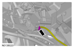
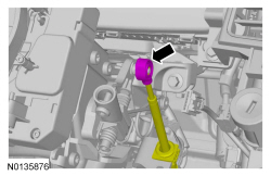
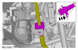
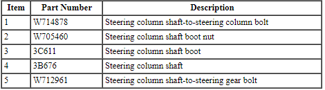
Steering Column Shaft - Intermediate
NOTE: Hydraulic Power Assist Steering (HPAS) steering column shown, Electronic Power Assist Steering (EPAS) steering column similar.
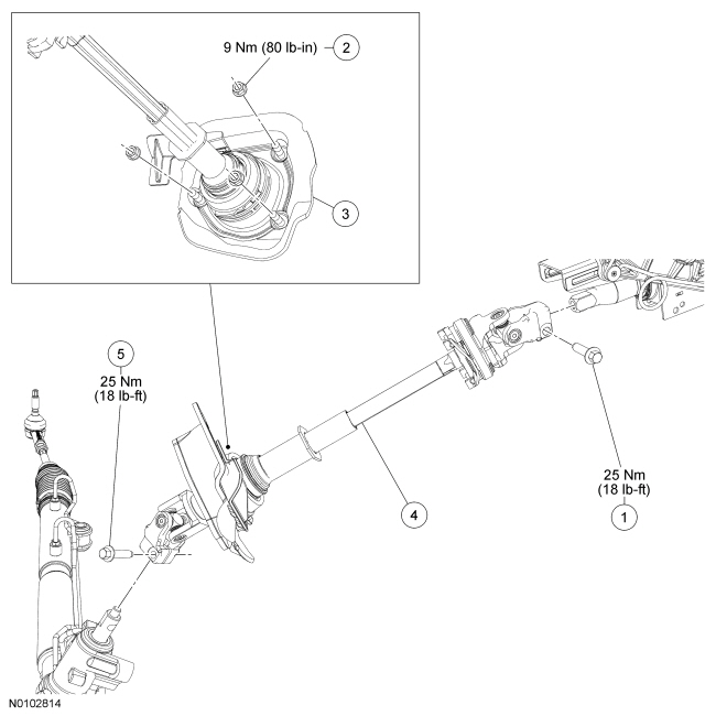
Removal and Installation
NOTICE: Do not allow the steering column shaft to rotate while the intermediate shaft is disconnected or damage to the clockspring may result. If there is evidence that the shaft has rotated, the clockspring must be removed and recentered. For additional information, refer to Section 501-20B.
- With the vehicle in NEUTRAL, position it on a hoist. For additional information, refer to Section 100-02.
- NOTE: Use a steering wheel holding device (such as Hunter
28-75-1 or equivalent).
Using a suitable holding device, hold the steering wheel in the straight-ahead position.
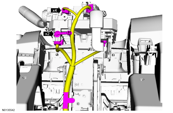
- Remove the 2 screws and the steering column opening trim panel.
- Remove the steering column shaft-to-steering column bolt.
- To install, tighten to 25 Nm (18 lb-ft).
- Remove the 3 steering column shaft boot nuts.
- To install, tighten to 9 Nm (80 lb-in).
- Remove the steering column shaft-to-steering gear bolt.
- To install, tighten to 25 Nm (18 lb-ft).
- Remove the steering column shaft.
- To install, reverse the removal procedure.
- If installing a new steering column shaft, transfer parts as needed.
- Remove the constant tension clamp and the steering column shaft boot.
- If installing a new steering column shaft, transfer parts as needed.
Steering Column Shroud
Removal and Installation
NOTE: Vehicle without column selector lever shown, vehicle with column selector lever similar.
NOTE: Removal steps in this procedure may contain installation details.
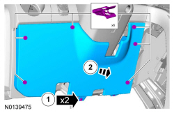
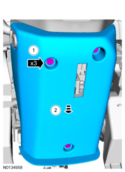
- To install, reverse the removal procedure.
- NOTICE: Make sure the column selector lever boot retaining
tabs are installed into the steering column shroud first, otherwise damage
to the column selector lever boot retaining tabs may occur.
If equipped with column selector lever.
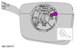
Heated Steering Wheel Module (HSWM)
Removal and Installation
- If a new HSWM is being installed, connect the scan tool and upload the module configuration information from the HSWM. For additional information on configuration, refer to PMI in Section 418-01.
- Remove the RH instrument panel finish panel. Refer to Section 501-12.
-
- To install, tighten to 3 Nm (27 lb-in).
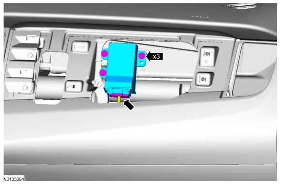
- To install, reverse the removal procedure.
- If a new HSWM was installed, it must be configured (using vehicle as-built data or module configuration information retrieved earlier in this procedure). For additional information on configuration, refer to PMI in Section 418-01.
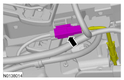
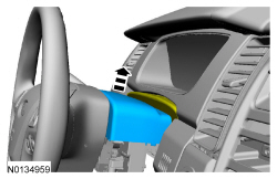
Steering Column Motor - Tilt
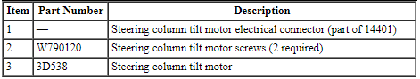
Removal and Installation
NOTE: Removal steps in this procedure may contain installation details.
- Remove the steering column shrouds. Refer to Steering Column Shroud.
- Remove the 2 screws, detach the in-vehicle temperature sensor and hose
assembly (if equipped) and remove the steering column opening trim panel.
- To install, tighten to 5 Nm (44 lb-in).
- Disconnect the steering column tilt motor electrical connector.
- Remove the 2 steering column tilt motor screws and the steering column
tilt motor.
- To install, tighten to 3 Nm (27 lb-in).
- To install, reverse the removal procedure.
 Power Steering
SPECIFICATIONS
Torque Specifications
a Refer to the procedure for the specification.
REMOVAL AND INSTALLATION
Steering Gear
Special Tool(s)
NOTE: 3.5L GTDI engine shown, 3.5L&nbs ...
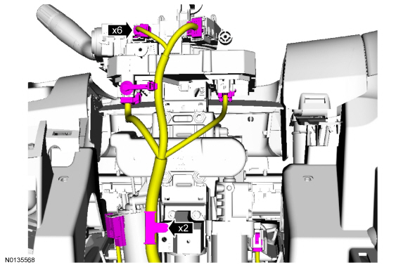
 Steering Column Switches
SPECIFICATIONS
Torque Specifications
DESCRIPTION AND OPERATION
Steering Column Switches
Overview
The steering column switches are located on or around the steering column,
giving the driver the abil ...
Other materials:
General information
See the following sections for directions on how to properly use safety
restraints for children.
WARNING: Always make sure your child is secured properly in a
device that is appropriate for their height, age and weight. Child
safety restraints must be bought separately from your vehicle. Failure ...
Exceptions
There are several exceptions to the Normal Schedule. They are listed
below:
Normal vehicle axle maintenance: Rear axles and power take-off
(PTO) units with synthetic fluid and light-duty trucks equipped with
Ford-design axles are lubricated for life; do not check or change fluid
unless a leak i ...
Lane keeping system
WARNING: The system is designed to aid the driver. It is
not intended to replace the driver’s attention and judgment.
The driver is still responsible to drive with due care and attention.
The system detects unintentional drifting toward the outside of the lane
and alerts and/or aids the driv ...
