SPECIFICATIONS
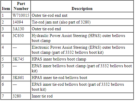
Torque Specifications
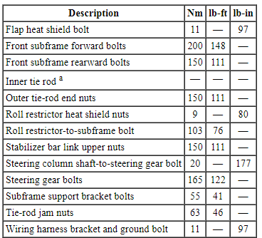
a Refer to the procedure for the specification.
REMOVAL AND INSTALLATION
Steering Gear
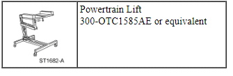
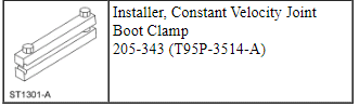
Special Tool(s)
NOTE: 3.5L GTDI engine shown, 3.5L Ti-VCT, 3.7L Ti-VCT and 2.0L GTDI similar.
Removal
All vehicles
- If installing a new steering gear, connect the scan tool and upload the module configuration information from the Power Steering Control Module (PSCM). Refer to Section 418-01.
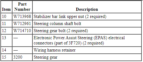
- NOTE: Use a steering wheel holding device (such as Hunter
28-75-1 or equivalent).
Install a holding device to hold the steering wheel in the straight-ahead position.
- Remove the wheels and tires. Refer to Section 204-04.
- NOTICE: Do not allow the steering column shaft to
rotate while disconnected from the gear or damage to the clockspring may
occur. If there is evidence that the steering column shaft has rotated,
remove and recenter the clockspring. Refer to Section 501-20B.
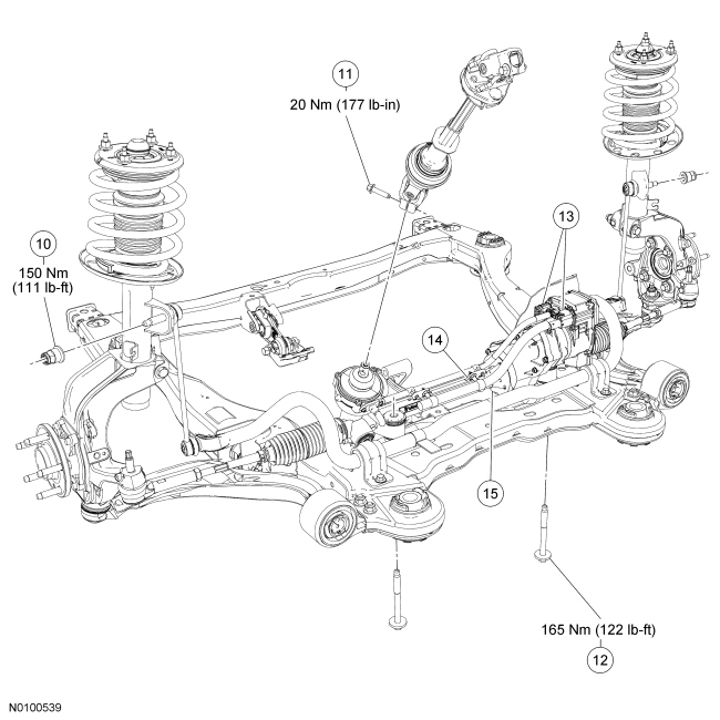
Remove the bolt and disconnect the steering column shaft from the steering gear.
- Discard the bolt.
- Remove the 2 stabilizer bar link upper nuts.
- Discard the nuts.
- Remove the 2 outer tie-rod end nuts and separate the tie-rod ends from the wheel knuckle.
- Remove the 4 retainers and the underbody shield, if equipped.
- Remove the 3 (some vehicles have only 2) RH engine splash shield-to-subframe pin-type retainers.
Vehicles equipped with a 3.5L Ti-VCT or 3.7L Ti-VCT engine
- Remove the Y-pipe. Refer to Section 309-00.
- Remove the 2 roll restrictor heat shield nuts and the engine roll restrictor heat shield.
Vehicles equipped with a 2.0L GTDI, 3.5L Ti-VCT, or 3.7L Ti-VCT engine
- Remove the roll restrictor-to-subframe bolt.
Vehicles equipped with a 3.5L GTDI engine
- Remove the RH and LH exhaust flexible pipes. Refer to Section 309-00.
- Remove the 2 front and rear roll restrictor-to-subframe bolts.
All vehicles
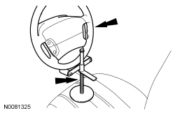
- Position the Powertrain Lift under the subframe.
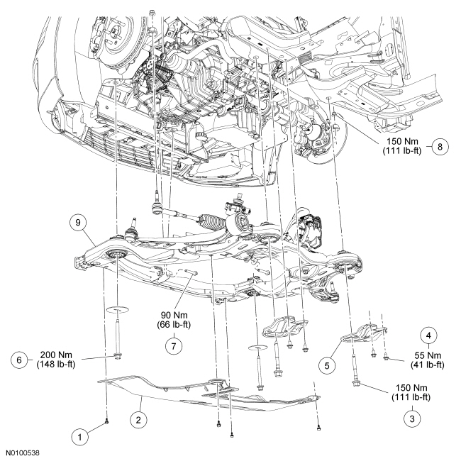
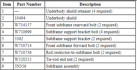
- Remove the 2 front subframe rearward bolts, the 4 support bracket bolts
and the 2 subframe support brackets.
- Loosen the 2 front subframe forward bolts.
- Lower the subframe to gain access to the steering gear.
- Remove the flap heat shield bolt and position the flap heat shield to access the Electronic Power Assist Steering (EPAS) electrical connectors.
- Remove the wiring harness bracket bolt and position the bracket and ground wire aside.

- Disconnect the 2 Electronic Power Assist Steering (EPAS) electrical connectors and the wiring retainer.
- NOTE: Position the stabilizer bar to the full up position.
Remove the 2 steering gear bolts.
- Remove the steering gear from the RH side of the vehicle.
Installation
All vehicles
- Position the steering gear and install the 2 bolts.
- Tighten to 165 Nm (122 lb-ft).
- Connect the 2 EPAS electrical connectors and the wiring retainer.
- Position the wiring harness bracket and ground wire, and install the
bolt.
- Tighten to 11 Nm (97 lb-in).
- Position the flap heat shield and install the bolt.
- Tighten to 11 Nm (97 lb-in).
- Raise the subframe.
- Position the 2 subframe support brackets and loosely install the 4 bolts.
- Install the 2 front subframe rearward bolts.
- Tighten the rearward bolts to 150 Nm (111 lb-ft).
- Tighten the forward bolts to 200 Nm (148 lb-ft).
- Tighten the 4 subframe support bracket bolts to 55 Nm (41 lb-ft).
Vehicles equipped with a 3.5L GTDI engine
- Install the 2 front and rear roll restrictor-to-subframe bolts.
- Tighten to 103 Nm (76 lb-ft).
- Install the RH and LH exhaust flexible pipes. Refer to Section 309-00.
Vehicles equipped with a 2.0L GTDI, 3.5L Ti-VCT or 3.7L Ti-VCT engine
- Install the roll restrictor-to-subframe bolt.
- Tighten to 103 Nm (76 lb-ft).
Vehicles equipped with a 3.5L Ti-VCT or 3.7L Ti-VCT engine
- Install the Y-pipe. Refer to Section 309-00.
- Position the roll restrictor heat shield and install the 2 roll
restrictor heat shield heat shield nuts.
- Tighten to 9 Nm (80 lb-in).
All vehicles
- Install the 3 (some vehicles have only 2) RH engine splash shield-to-subframe pin-type retainers.
- Position the underbody shield and install the 4 retainers.
- Position the 2 outer tie-rod ends and install the nuts.
- Tighten to 150 Nm (111 lb-ft).
- Connect the stabilizer bar links and install the 2 nuts.
- Tighten the new nuts to 150 Nm (111 lb-ft).
- NOTICE: Do not allow the steering column shaft to
rotate while disconnected from the gear or damage to the clockspring may
occur. If there is evidence that the steering column shaft has rotated,
remove and recenter the clockspring. Refer to Section 501-20B.
With the locator on the input shaft correctly aligned, connect the steering column shaft to the steering gear and install the new bolt.
- Tighten to 20 Nm (177 lb-in).
- Install the wheels and tires. Refer to Section 204-04.
- When installing a new steering gear, it must be configured (using vehicle as-built data or module configuration information retrieved earlier in this procedure). Refer to Programmable Module Installation (PMI) in Section 418-01.
- Check, and if necessary, adjust the front toe. Refer to Section 204-00.
Tie Rod - Inner
Special Tool(s)
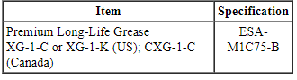
Material
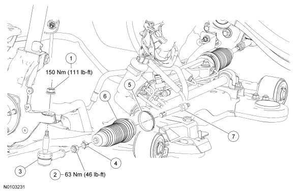
NOTE: Hydraulic Power Assist Steering (HPAS) gear shown, Electronic Power Assist Steering (EPAS) gear similar.
Removal
NOTICE: When servicing inner tie rods, a new bellows boot and clamps must be installed. The boots and clamps are designed to provide an airtight seal and protect the internal components of the steering gear. If the seal is not airtight, the vacuum generated during turning will draw water and contamination into the gear, causing failure of the steering gear components. Zip ties must not be used as they do not provide an airtight seal.
NOTICE: The inner ball joint grease is not compatible with water contamination. Do not allow water to become trapped in the grease or degradation and failure of the joint may occur.
NOTICE: If present, the orientation of the vent tube must be noted so the boots and vent tubes can be installed in the correct location. Incorrect orientation may lead to improper ventilation and steering gear failure.
NOTE: If the RH inner tie rod is being serviced, the LH outer tie-rod end and bellows boot must also be removed to access and hold the steering gear rack when loosening and tightening the inner tie rod.
- With the vehicle in NEUTRAL, position it on a hoist. For additional information, refer to Section 100-02.
- Loosen the tie-rod jam nut(s).
- NOTE: The hex-holding feature can be used to prevent turning of
the stud while removing the nut.
Remove the outer tie-rod end nut(s) and disconnect the outer tie-rod end from the wheel knuckle(s).
- NOTE: Count and record the number of turns required to remove the
outer tie-rod end for reference during installation.
Remove the outer tie-rod end(s).
- Remove the tie-rod jam nut(s).
- Remove and discard the inner and outer bellows boot clamps.
- Remove and discard the bellows boot(s).
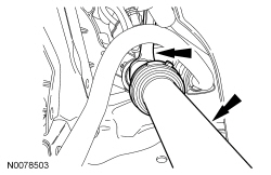
- NOTICE: The steering gear rack must be held while loosening or
tightening the inner tie rod or damage to the steering gear may occur. Place
the steering gear at the center position. Use an appropriate-sized wrench on
the flat/teeth of the rack to resist rotation and to prevent damage during
removal of the inner tie rod.
NOTE: An assistant will be needed to hold the steering gear rack on the LH side when servicing the RH inner tie rod.
NOTE: Crowfoot-style inner tie-rod tool shown.
While holding the steering gear rack, use a suitable crowfoot-style inner tie-rod tool (such as Snap On Stock# YA3000B) or an appropriate-sized crowfoot wrench to remove the inner tie rod.
Installation
- NOTICE: The steering gear rack must be held while loosening or
tightening the inner tie rod or damage to the steering gear may occur. Place
the steering gear at the center position. Use an appropriate-sized wrench on
the flat/teeth of the rack to resist rotation and to prevent damage during
removal of the inner tie rod.
NOTE: An assistant will be needed to hold the steering gear rack on the LH side when servicing the RH inner tie rod.
NOTE: Crowfoot-style inner tie-rod tool shown.
While holding the steering gear rack, use a suitable crowfoot-style inner tie-rod tool (such as Snap On Stock# YA3000B) or an appropriate-sized crowfoot wrench to install the inner tie rod.- For Hydraulic Power Assist Steering (HPAS) gears, tighten to 105 Nm (77 lb-ft).
- For Electronic Power Assist Steering (EPAS) gears, tighten to 90 Nm (66 lb-ft).

- Apply the specified grease to the steering gear-to-bellows boot mating surfaces and bellows boot grooves in the inner tie-rod casting.
- NOTE: Make sure the steering gear bellows is positioned correctly
over the steering gear housing bead and the grooves in the inner tie-rod
casting.
NOTE: Make sure the steering gear bellows is not twisted and the vent tube (if equipped) is securely inserted into the vent nipple of the steering gear bellows.
Position the new inner bellows boot clamp(s) on the new bellows boot(s) and install the bellows boot(s).
- NOTICE: Make sure that the end of the steering gear bellows
boot is positioned between the 2 grooves on the inner tie rod or an internal
leak may occur.
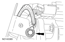
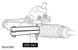
Using the Constant Velocity Joint Boot Clamp Installer, crimp/tighten the inner bellows boot clamp(s).
- Install the outer bellows boot clamp(s).
- Thread the tie-rod jam nut(s) onto the inner tie rod(s).
- NOTE: Install the outer tie rod the same number of turns recorded
during removal.
Thread the outer tie rod(s) onto the inner tie rod(s).
- NOTE: The hex-holding feature can be used to prevent turning of
the stud while installing the nut.
Connect the outer tie-rod end(s) to the wheel knuckle(s) and install the nut(s).
- Tighten to 150 Nm (111 lb-ft).
- Tighten the tie-rod jam nut(s) to 63 Nm (46 lb-ft).
- Check and, if necessary, adjust the front toe. For additional information, refer to Section 204-00.
 Steering System
DESCRIPTION AND OPERATION
Steering System
Electronic Power Assist Steering (EPAS) System
The Electronic Power Assist Steering (EPAS) system consists of the following
components:
Power Steering Cont ...
 Steering Column
SPECIFICATIONS
Torque Specifications
DESCRIPTION AND OPERATION
Steering Column
The steering column system consists of the following components:
Intermediate shaft
Steering column
SCCM (if eq ...
Other materials:
Using Adaptive Cruise Control
WARNING: Always pay close attention to changing road
conditions, especially when using adaptive cruise control.
Adaptive cruise control cannot replace attentive driving. Failing to
follow any of the warnings below or failing to pay attention to the road
may result in a collision, serious injur ...
General Procedures
Sectioning Guidelines
General Equipment
Material
NOTE: The following illustration provides recommended sectioning
points. Cut lines shown in illustration are approximate.
WARNING:
Collision damage repair must conform to the instructions contained in this
workshop manual. Replacement ...
Side airbags
WARNING: Do not place objects or mount equipment on or near
the airbag cover, on the side of the seatbacks (of the front seats),
or in front seat areas that may come into contact with a deploying
airbag. Failure to follow these instructions may increase the risk of
personal injury in the event o ...
