SPECIFICATIONS
General Specifications

Material
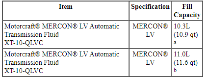
a 6F50 transmission.
b 6F55 transmission.
Torque Specifications
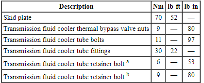
a 3.5L GTDI
b 3.5L Ti-VCT
DESCRIPTION AND OPERATION
Transaxle Cooling
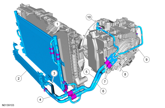
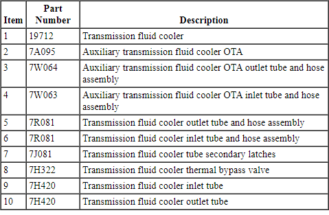
The transmission fluid cooling system consists of the following:
- OTA transmission fluid combo cooler
- Auxiliary transmission fluid cooler OTA (model dependent)
- Transmission fluid cooler tube assembly
- Thermal bypass valve
- Transmission fluid cooler outlet tube
- Transmission fluid cooler return tube
This vehicle is equipped with an external OTA transmission fluid cooler. The OTA transmission fluid cooler is part of the A/C condenser and cannot be serviced separately. The OTA transmission fluid cooler is mounted in front of the engine radiator. There is also an auxiliary transmission fluid cooler OTA which is model dependent. If equipped, the auxiliary transmission fluid cooler OTA is mounted in front of the A/C condenser. The cooling system also consists of a thermal bypass valve which is mounted on the transaxle main control cover. When the transmission fluid is below normal operating temperature, transmission fluid travels from the transaxle to the thermal bypass valve and back to the transaxle. When the transmission fluid is at or above normal operating temperature, the thermal bypass valve opens allowing transmission fluid to travel from the transaxle through the OTA transmission fluid cooler and back to the transaxle. The OTA transmission fluid cooler transfers heat from the transmission fluid to the outside air.
Transaxle Cooling - 3.5L Engine Ti-VCT
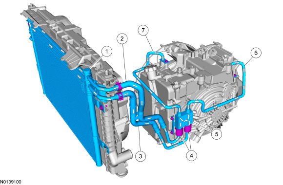
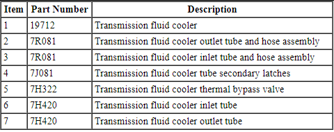
Transaxle Cooling - 3.5L GTDI Engine
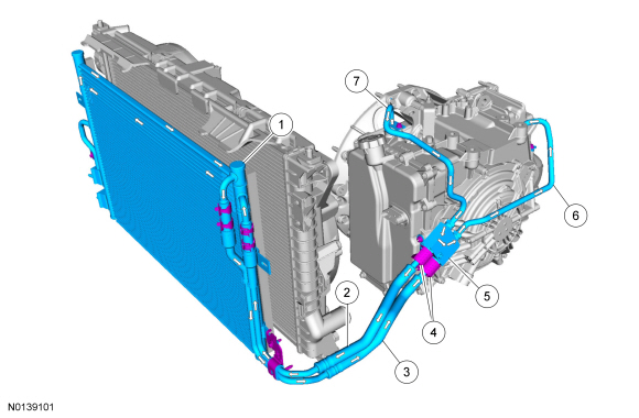
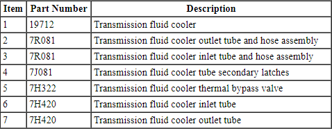
Transaxle Cooling - 3.5L Ti-VCT Engine with an auxiliary transmission fluid cooler OTA
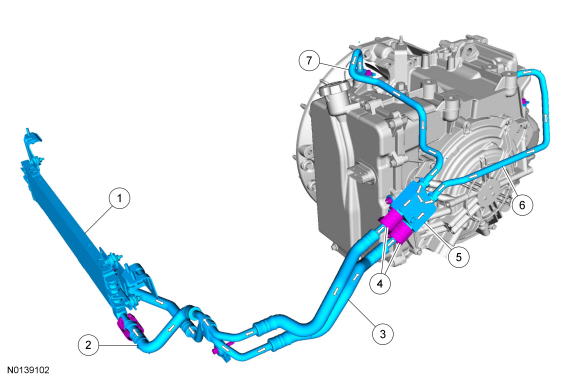
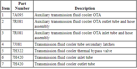
Transaxle Cooling - 3.5L GTDI Engine with an auxiliary transmission fluid cooler OTA
DIAGNOSIS AND TESTING
Transaxle Cooling
Material

Inspection and Verification
- Verify the customer concern by operating the vehicle to duplicate the condition.
- If the inspection reveals obvious concern(s) that can be readily identified, repair as necessary.
- Install new components if a transmission fluid leak is found in any of the transmission cooling components.
- If the concern(s) remains after the inspection, determine the symptom(s). GO to Symptom Chart - Transmission Cooling or GO to Symptom Chart - NVH.
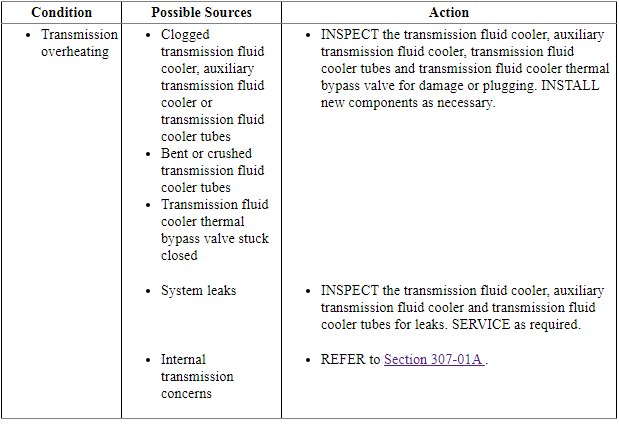
Symptom Chart - Transmission Cooling
Symptom Chart - NVH
NOTE: NVH symptoms should be identified using the diagnostic tools that are available. For a list of these tools, an explanation of their uses and a glossary of common terms, refer to Section 100-04. Since it is possible any one of multiple systems may be the cause of a symptom, it may be necessary to use a process of elimination type of diagnostic approach to pinpoint the responsible system. If this is not the causal system for the symptom, refer back to Section 100-04 for the next likely system and continue diagnosis.

Check Transmission Fluid Level and Condition
NOTICE: The vehicle should not be driven if the transmission fluid level indicator shows the transmission fluid below the minimum transmission fluid level mark or internal failure could result.
If the vehicle has been operated for an extended period of time, at highway speeds, in city traffic, in hot weather or while pulling a trailer, the transmission fluid needs to cool down to obtain an accurate reading.
The transmission fluid level reading on the transmission fluid level indicator will differ depending on operating and ambient temperatures. The correct reading should be within the normal operating temperature range.
Transmission Fluid Level Check
NOTE: The transmission fluid should be checked at normal operating temperature 82ÂşC-93ÂşC (180ÂşF-200ÂşF) on a level surface. Normal operating temperature can be reached after approximately 32 km (20 mi) of driving and can be checked using the scan tool.
Under normal circumstances, the transmission fluid level should be checked during normal maintenance. If the transmission starts to slip, shifts slowly or shows signs of transmission fluid leaking, the transmission fluid level should be checked.
- With the transmission in PARK, the engine at idle, brake pedal applied, move the selector lever through each gear and allow each gear to engage. Place the selector lever in the PARK position.
- Wipe the transmission fluid level indicator cap and remove the transmission fluid level indicator.
- Wipe the transmission fluid level indicator with a clean cloth.
- Install the transmission fluid level indicator back in the transmission until it is fully seated, then remove the indicator. The transmission fluid level should be within the normal operating range.
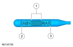
- Correct transmission fluid level at normal operating temperature 82ÂşC-93ÂşC (180ÂşF-200ÂşF)
- Low transmission fluid level
- High transmission fluid level
High Transmission Fluid Level
A transmission fluid level that is too high may cause the transmission fluid to become aerated due to the churning action of the rotating internal parts. This will cause erratic control pressure, foaming, loss of transmission fluid from the vent tube and possible transmission malfunction and/or damage.
Low Transmission Fluid Level
A low transmission fluid level could result in poor transmission engagement, slipping, malfunction and/or damage. This could also indicate a leak in one of the transmission seals or gaskets.
Adding Transmission Fluid
NOTICE: The use of any transmission fluid other than what is recommended for this transmission will cause transmission damage.
If transmission fluid needs to be added, add transmission fluid in 0.25L (1/2 pt) increments to the transmission. Do not overfill the transmission.
Transmission Fluid Condition Check
- Check the transmission fluid level.
- Hold the transmission fluid level indicator over a white facial tissue and allow the transmission fluid to drip onto the facial tissue and examine the stain.
- If evidence of solid material is found, the transmission fluid pan should be removed for further inspection.
- If transmission fluid contamination or transmission failure is confirmed by the sediment in the bottom of the transmission fluid pan, repair the transmission and clean the transmission fluid cooler tubes and the transmission fluid cooler.
- If the transmission is to be overhauled or if installing a new transmission, the transmission fluid cooler must be backflushed. Refer to Transmission Fluid Cooler Backflushing and Cleaning.
GENERAL PROCEDURES
Transmission Fluid Cooler Backflushing and Cleaning
Special Tool(s)

Material

NOTICE: Use transmission fluid specified for this transmission. Do not use any supplemental transmission fluid additives or cleaning agents. The use of these products could cause internal transmission components to fail, which will affect the operation of the transmission.
NOTE: Transmission fluid cooler backflushing will be carried out using the Transmission Heated Cooler Line Flusher. Follow the manufacturer's instructions included with the machine. Test the equipment to make sure that a vigorous fluid flow is present before proceeding.
NOTE: If the Transmission Heated Cooler Line Flusher or equivalent is not available, install a new transmission fluid cooler and/or an auxiliary transmission fluid cooler.
- Check and top off fluid level of the cooler line flusher with transmission fluid.
- Allow the fluid in the cooler line flusher 15-30 minutes to heat up to 60ÂşC (140ÂşF) before using.
- Install the line adapters on the transmission fluid cooler tubes.
- NOTE: The FRONT transmission fluid cooler tube on the thermal
bypass valve is the transmission fluid cooler pressure tube.
Attach the cooler line flusher red line to the transmission fluid cooler pressure tube quick disconnect fitting.
- Attach the cooler line flusher blue line to the transmission fluid cooler return tube quick disconnect fitting.
- Follow the equipment instructions to purge the transmission fluid cooler tubes and transmission fluid cooler prior to starting the flushing procedure.
- Allow the transmission fluid cooling system to backflush for 10-15 minutes, then flush the transmission fluid cooler in a normal flow direction for an additional 10-15 minutes.
- Clean the transmission mounted fluid cooler tubes by hand and replace the thermal bypass valve.
REMOVAL AND INSTALLATION
Transmission Fluid Cooler
- NOTE: The transmission fluid cooler is part of the A/C condenser
assembly and cannot be serviced separately. If equipped, the Auxiliary
Transmission Fluid Cooler - Oil-to-Air Fluid Cooler can be serviced
separately.
If installation of a new transmission fluid cooler is required, refer to Condenser Core in Section 412-01.
If Installation of a new Auxiliary Transmission Fluid Cooler - Oil-to-Air Fluid Cooler is required, refer to Auxiliary Transmission Fluid Cooler - Oil-to-Air Fluid Cooler.
Transmission Fluid Cooler Tubes - 3.5L Ti-VCT
Special Tool(s)

Material

Removal
All Vehicles
NOTICE: The use of any transmission fluid other than what is recommended for this transaxle will cause transaxle damage.
- With the vehicle in NEUTRAL, position it on a hoist. Refer to Section 100-02.
- Remove the ACL and outlet pipe. Refer to Section 303-12.
- Remove the battery tray. Refer to Section 414-01.
Vehicles without an auxiliary transmission fluid cooler
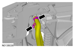
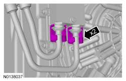
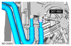
Vehicles with an auxiliary transmission fluid cooler
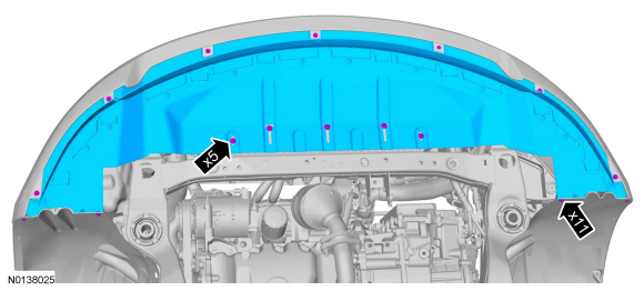
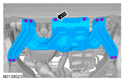
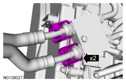
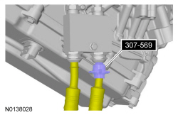
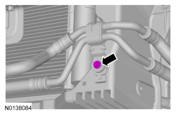
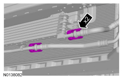
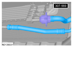
All vehicles
- Discard the specified component. Follow local disposal regulations.
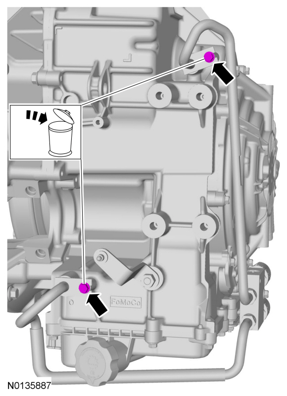
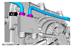
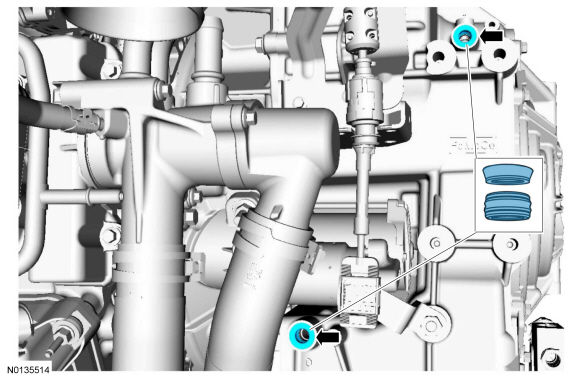
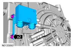
Installation
All vehicles
-
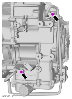
- Tighten to 9 Nm (80 lb-in).
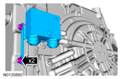
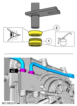
- Visual check. Apply the specified lubricant to the specified component.
Material: Motorcraft MERCON LV Automatic Transmission Fluid XT-10-QLVC.- Seal (7D258)
- Backing ring (7J324)
- Tighten to 30 Nm (22 lb-ft).
-
- Tighten to 11 Nm (97 lb-in).
Vehicles with an auxiliary transmission fluid cooler
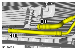
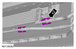
-
- Tighten to 9 Nm (80 lb-in).
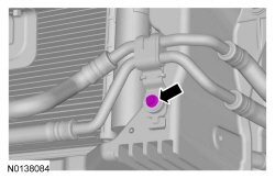
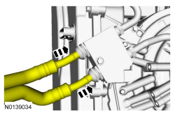
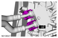
-
- Tighten to 70 Nm (52 lb-ft).
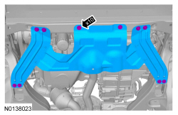
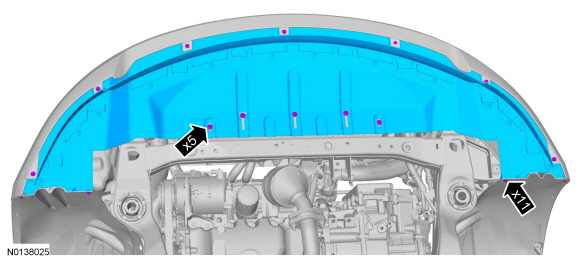
Vehicles without an auxiliary transmission fluid cooler
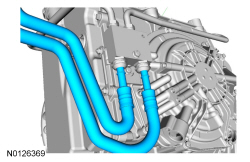
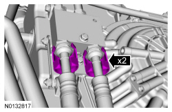
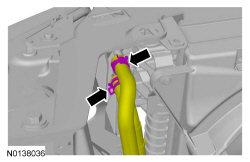
All vehicles
- Install the battery tray. Refer to Section 414-01.
- Install the ACL and outlet pipe. Refer to Section 303-12.
- Check the transmission fluid level and add transmission fluid as necessary.
Transmission Fluid Cooler Tubes - 3.5L GTDI
Special Tool(s)

Material

Removal
All Vehicles
NOTICE: The use of any transmission fluid other than what is recommended for this transaxle will cause transaxle damage.
- With the vehicle in NEUTRAL, position it on a hoist. Refer to Section 100-02.
- Remove the Air Cleaner (ACL) and outlet pipe. Refer to Section 303-12.
- Remove the battery tray. Refer to Section 414-01.
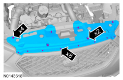
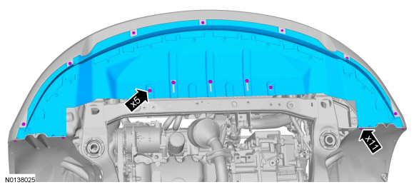
Vehicles without an auxiliary transmission fluid cooler
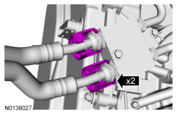
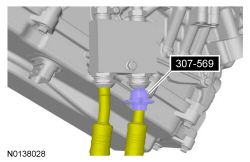
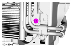
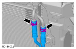
Vehicles with an auxiliary transmission fluid cooler
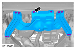
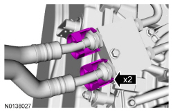
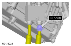
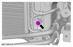
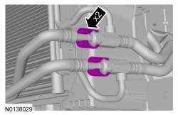
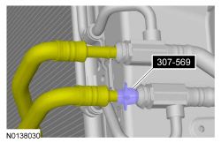
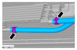
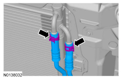
All vehicles
- Discard the specified component. Follow local disposal regulations.
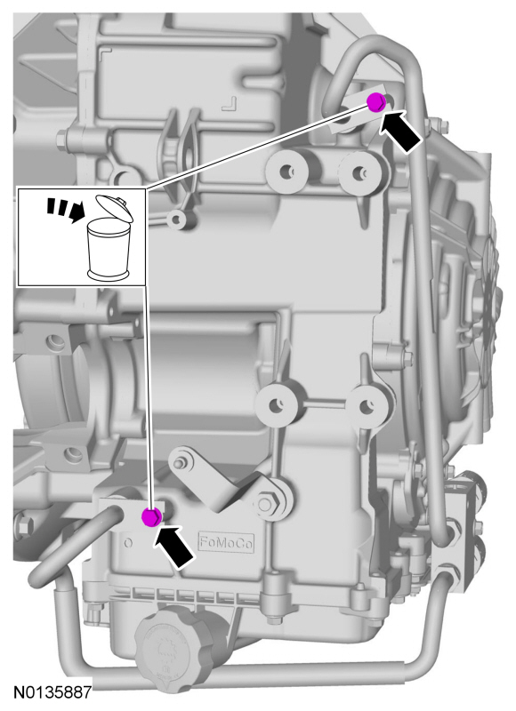
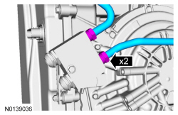
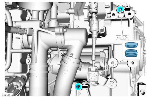
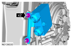
Installation
All vehicles
-
- Tighten to 9 Nm (80 lb-in).
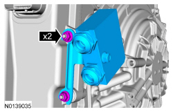
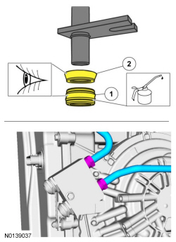
- Visual check. Apply the specified lubricant to the specified component.
Material: Motorcraft MERCON LV Automatic Transmission Fluid XT-10-QLVC.- Seal (7D258)
- Backing ring (7J324)
- Tighten to 30 Nm (22 lb-ft).
-
- Tighten to 11 Nm (97 lb-in).
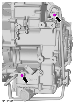
Vehicles with an auxiliary transmission fluid cooler
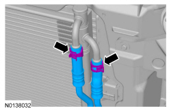
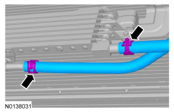
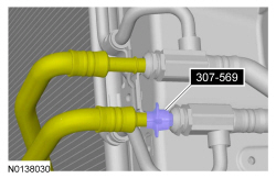
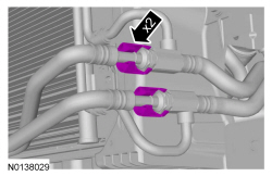
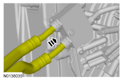
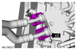
-
- Tighten to 6 Nm (53 lb-in).
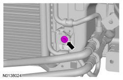
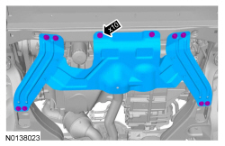
Vehicles without an auxiliary transmission fluid cooler
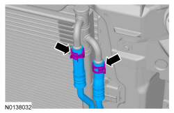
-
- Tighten to 6 Nm (53 lb-in).
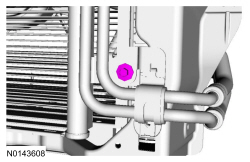
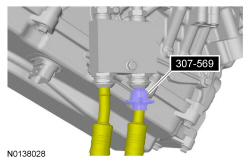
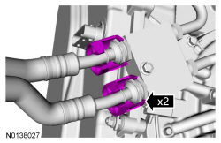
All Vehicles
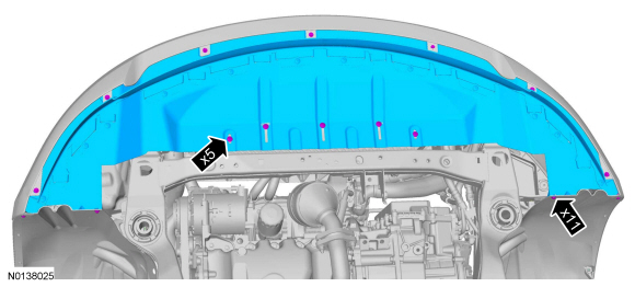
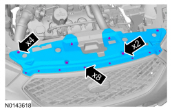
- Install the battery tray. Refer to Section 414-01.
- Install the ACL and outlet pipe. Refer to Section 303-12.
- Check the transmission fluid level and add transmission fluid as necessary.
Transmission Fluid Cooler Tubes - 3.7L Ti-VCT
Special Tool(s)

Material

Removal
NOTICE: The use of any transmission fluid other than what is recommended for this transaxle will cause transaxle damage.
- With the vehicle in NEUTRAL, position it on a hoist. Refer to Section 100-02.
- Remove the ACL and outlet pipe. Refer to Section 303-12.
- Remove the battery tray. Refer to Section 414-01.
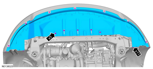
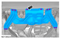
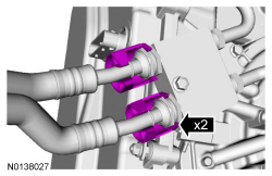
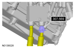
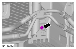
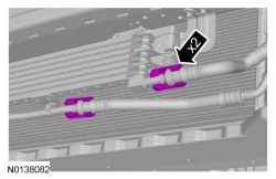
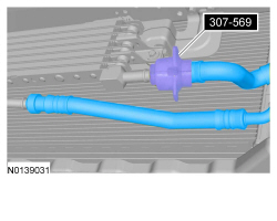
- Discard the specified component. Follow local disposal regulations.
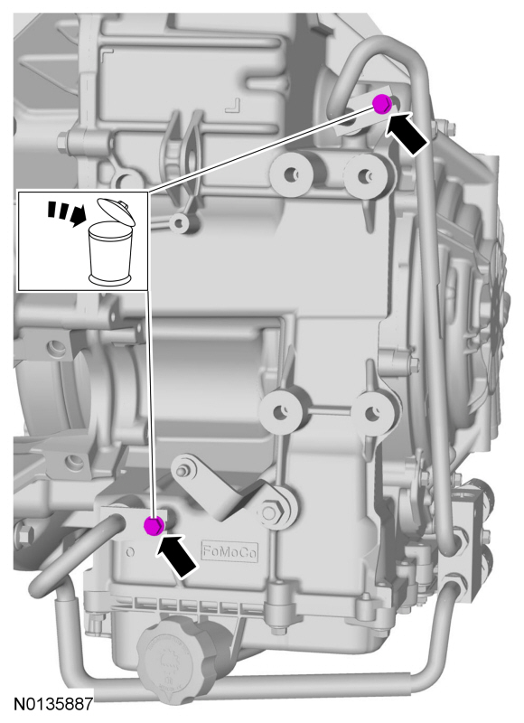
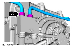
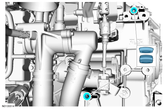
Installation
- Visual check. Apply the specified lubricant to the specified component.
Material: Motorcraft MERCON LV Automatic Transmission Fluid XT-10-QLVC.- Seal (7D258)
- Backing ring (7J324)
- Tighten to 30 Nm (22 lb-ft).
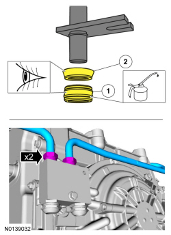
-
- Tighten to 11 Nm (97 lb-in).
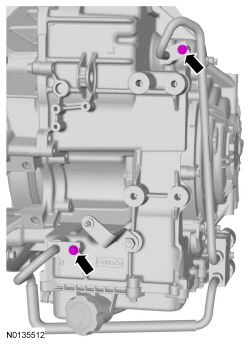
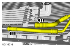
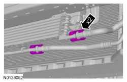
-
- Tighten to 9 Nm (80 lb-in).
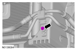
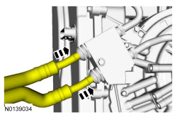
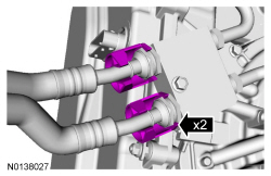
-
- Tighten to 70 Nm (52 lb-ft).
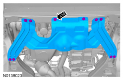
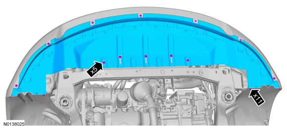
- Install the battery tray. Refer to Section 414-01.
- Install the ACL and outlet pipe. Refer to Section 303-12.
- Check the transmission fluid level and add transmission fluid as necessary.
Auxiliary Transmission Fluid Cooler - Oil-to-Air Fluid Cooler
Material

Removal
All vehicles
- With the vehicle in NEUTRAL, position it on a hoist. Refer to Section 100-02.
3.5L Ti-VCT
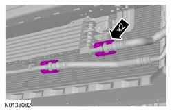
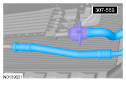
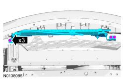
3.5L GTDI
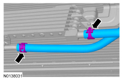
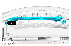
Installation
3.5L GTDI
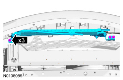
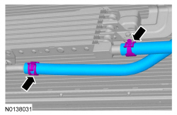
3.5L Ti-VCT
-
- Tighten to 8 Nm (71 lb-in).
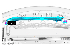
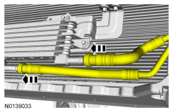
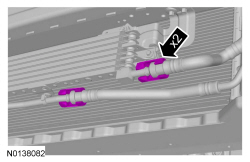
All vehicles
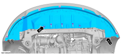
- Fill with transmission fluid and check for leaks.
Cooler Bypass Valve
Special Tool(s)

Material

Removal
All Vehicles
NOTICE: The use of any transmission fluid other than what is recommended for this transaxle will cause transaxle damage.
- With the vehicle in NEUTRAL, position it on a hoist. Refer to Section 100-02.
- Remove the Air Cleaner (ACL) and outlet pipe. Refer to Section 303-12.
- Remove the battery tray. Refer to Section 414-01.
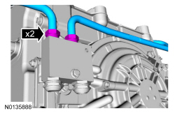
Vehicles without an auxiliary transmission fluid cooler
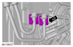
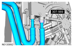
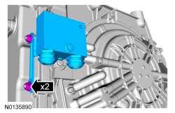
Vehicles with an auxiliary transmission fluid cooler
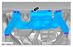
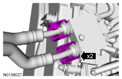
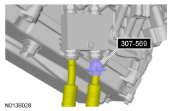
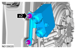
Installation
Vehicles with an auxiliary transmission fluid cooler
-
- Tighten to 9 Nm (80 lb-in).
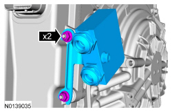
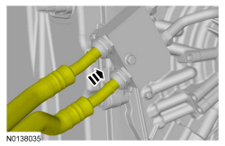
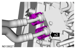
-
- Tighten to 70 Nm (52 lb-ft).
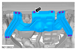
Vehicles without an auxiliary transmission fluid cooler
-
- Tighten to 9 Nm (80 lb-in).
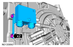
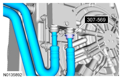
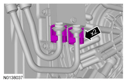
All Vehicles
-
- Tighten to 30 Nm (22 lb-ft).
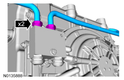
- Install the battery tray. Refer to Section 414-01.
- Install the ACL and outlet pipe. Refer to Section 303-12.
- Check the transmission fluid level and add transmission fluid as necessary.
 Disassembly and Assembly
Main Control - Overhaul
Special Tool(s)
Main Control
Main Control Valve Body
Solenoid Body
Main Control Valve Body
Check balls
Solenoid damper
NOTICE ...
 Transaxle/Transmission Cooling - 6F35
SPECIFICATIONS
Material
Torque Specifications
DESCRIPTION AND OPERATION
Transaxle Cooling
The transmission fluid cooling system consists of the following:
OTA transmission fluid cooler
Front ...
Other materials:
Diagnosis and Testing
Information and Entertainment System
Special Tool(s)
DTC Chart(s)
NOTE: For SYNC related concerns, REFER to the SYNC Symptom Chart
before connecting the scan tool and beginning DTC-based diagnostics.
Diagnostics in this manual assume a certain skill level and knowledge of
Ford-specific diagn ...
Body System - General Information
SPECIFICATIONS
Material
DESCRIPTION AND OPERATION
Insulation
Insulation is used as a sound-deadener to reduce exterior road and powertrain
noises from the interior of the vehicle. Mastic insulators are also used as
insulation. For information on the location of the mastic insulators, refer
to&nb ...
Safety Belts
PRINCIPLES OF OPERATION
WARNING: Never let a passenger hold a child on his or her lap
while your vehicle is moving. The passenger cannot protect the
child from injury in a crash.
WARNING: It is extremely dangerous to ride in a cargo area,
inside or outside of a vehicle. In a crash, people ridin ...
