SPECIFICATIONS
Material

Torque Specifications

DESCRIPTION AND OPERATION
Transaxle Cooling
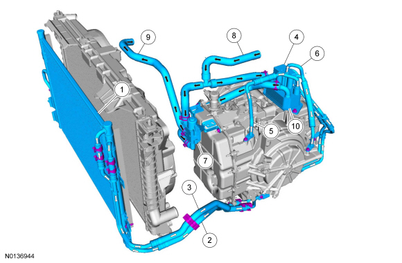
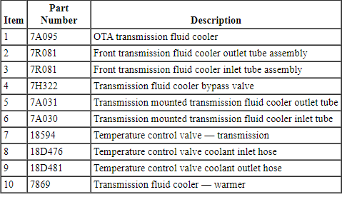
The transmission fluid cooling system consists of the following:
- OTA transmission fluid cooler
- Front transmission fluid cooler tube assembly
- Rear transmission fluid cooler tube assembly
- Transmission mounted transmission fluid cooler outlet tube
- Transmission mounted transmission fluid cooler inlet tube
- Transmission fluid cooler bypass valve
- Transmission fluid cooler - warmer
These vehicles are equipped with an OTA transmission fluid cooler and an in-tank transmission fluid cooler. The transmission fluid cooling system also consists of a transmission fluid cooler - warmer assembly which has a transmission cooler bypass valve mounted to the top of the transmission fluid cooler - warmer. Transmission fluid travels from the transmission to the transmission fluid cooler - warmer. The transmission fluid cooler - warmer warms the transmission fluid to the transmission operating temperature using heated engine coolant. When the transmission fluid is at or above normal operating temperature, the transmission fluid cooler bypass valve opens allowing transmission fluid to travel from the transmission through the in-tank transmission fluid cooler then through the OTA transmission fluid cooler then back to the transmission. The transmission fluid cooler transfers heat from the transmission fluid to the outside air.
Transmission Cooling
DIAGNOSIS AND TESTING
Transaxle Cooling
Material

Inspection and Verification
- Verify the customer concern by operating the vehicle to duplicate the condition.
- If the inspection reveals obvious concern(s) that can be readily identified, repair as necessary.
- Install new components if a transmission fluid leak is found in any of the transmission cooling components.
- If the concern(s) remains after the inspection, determine the symptom(s). GO to Symptom Chart.
DTC Chart
Diagnostics in this manual assume a certain skill level and knowledge of Ford-specific diagnostic practices. Refer to Diagnostic Methods in Section 100-00 for more information.
DTC Chart

Symptom Chart
Diagnostics in this manual assume a certain skill level and knowledge of Ford-specific diagnostic practices. Refer to Diagnostic Methods in Section 100-00 for more information.
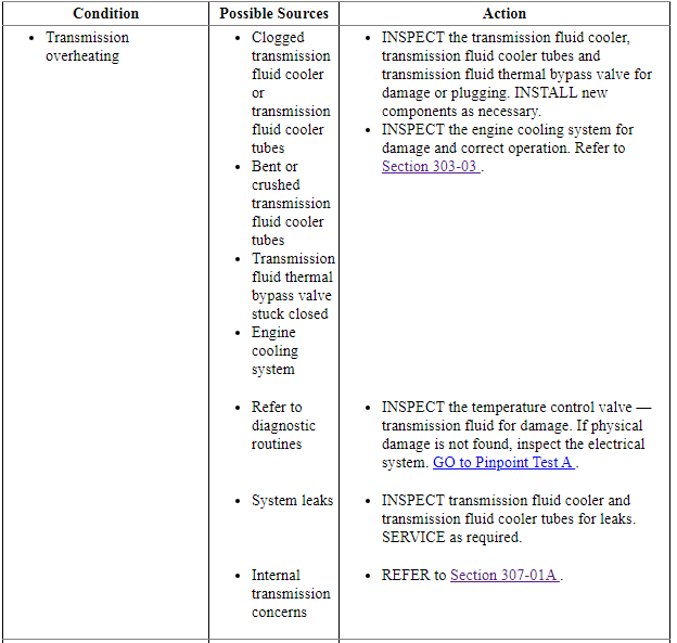

Check Transmission Fluid Level and Condition
Transmission Fluid Level Check
To check the transmission fluid level, refer to Section 307-01B.
High Transmission Fluid Level
A transmission fluid level that is too high may cause the transmission fluid to become aerated due to the churning action of the rotating internal parts. This will cause erratic control pressure, foaming, loss of transmission fluid from the vent tube and possible transmission malfunction and/or damage.
Low Transmission Fluid Level
A low transmission fluid level could result in poor transmission engagement, slipping, malfunction and/or damage. This could also indicate a leak in one of the transmission seals or gaskets.
Transmission Fluid Condition Check
- Check the transmission fluid level. Refer to Section 307-01B.
- Place a drop of transmission fluid on a facial tissue and examine the stain.
- If evidence of solid material is found, the transmission fluid pan should be removed for further inspection.
- If transmission fluid contamination or transmission failure is confirmed by the sediment in the bottom of the transmission fluid pan, repair the transmission and clean the transmission fluid cooler tubes and the transmission fluid cooler.
- If the transmission is to be overhauled or if installing a new transmission, the transmission fluid cooler must be backflushed. Refer to Transmission Fluid Cooler Backflushing and Cleaning.
Pinpoint Tests
Diagnostics in this manual assume a certain skill level and knowledge of Ford-specific diagnostic practices. Refer to Diagnostic Methods in Section 100-00 for more information.
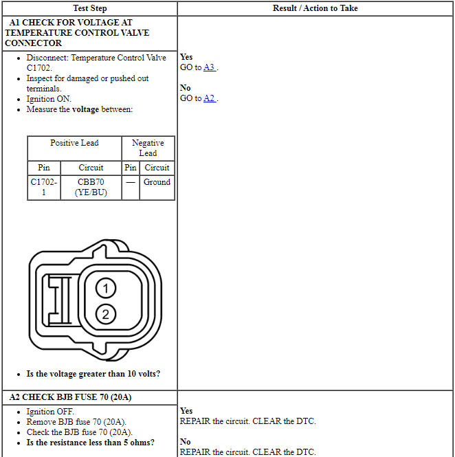
Pinpoint Test A: Transmission Over Temperature
Diagnostic Overview
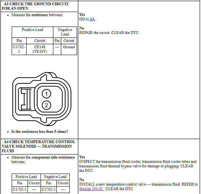
Damaged temperature control valve, electrical connector or circuitry may cause this DTC to set.
Refer to Wiring Diagrams Cell 23 for schematic and connector information.
Normal Operation and Fault Conditions
The temperature control valve directs warm engine coolant to the transmission fluid cooler/warmer mounted on the transmission during transmission warm-up and allows the coolant to bypass the warmer when the transmission fluid reaches normal operating temperature. The DTC sets when the PCM detects a transmission over temperature condition greater than 135ÂşC (275ÂşF) for at least 5 seconds. Torque converter lockup occurs earlier than expected and the PCM will turn on wrench lamp.
DTC Fault Trigger Conditions

-
Possible Sources
- Damaged transmission fluid temperature control valve
PINPOINT TEST A: TRANSMISSION OVER TEMPERATURE CONDITION

GENERAL PROCEDURES
Transmission Fluid Cooler Backflushing and Cleaning
Special Tool(s)

Material

NOTICE: Use transmission fluid specified for this transmission. Do not use any supplemental transmission fluid additives or cleaning agents. The use of these products could cause internal transmission components to fail, which will affect the operation of the transmission.
NOTE: Transmission fluid cooler backflushing will be carried out using the Transmission Heated Cooler Line Flusher. Follow the manufacturer's instructions included with the machine. Test the equipment to make sure that a vigorous fluid flow is present before proceeding.
- Check and top off fluid level of the cooler line flusher with transmission fluid.
- Allow the fluid in the cooler line flusher 15-30 minutes to heat up to 60ÂşC (140ÂşF) before using.
- Install the line adapters on the transmission fluid cooler tubes.
- NOTE: The front transmission fluid cooler tube assembly pressure
tube is the tube with out the quick disconnect fitting attached to the hose.
Attach the cooler line flusher red line to the front transmission fluid cooler tube assembly pressure tube.
- Attach the cooler line flusher blue line to the transmission fluid cooler tube assembly return tube quick disconnect fitting.
- Follow the equipment instructions to purge the transmission fluid cooler tubes and transmission fluid cooler prior to starting the flushing procedure.
- Allow the transmission fluid cooling system to backflush for 10-15 minutes, then flush the transmission fluid cooler in a normal flow direction for an additional 10-15 minutes.
- Clean the transaxle mounted fluid cooler tubes and the cooler bypass valve by hand.
REMOVAL AND INSTALLATION
Transmission Fluid Cooler
- NOTE: The transmission fluid cooler is part of the A/C condenser
assembly and cannot be serviced separately.
If installation of a new transmission fluid cooler is required, refer to Condenser Core in Section 412-01.
Transmission Fluid Cooler - Warmer
Material

Removal
- With the vehicle in NEUTRAL, position it on a hoist. Refer to Section 100-02.
- Drain the engine cooling system. Refer to Section 303-03.
- Remove the ACL. Refer to Section 303-12.
- Remove the ACL outlet pipe. Refer to Section 303-12.
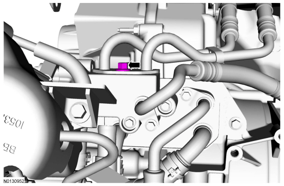
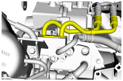
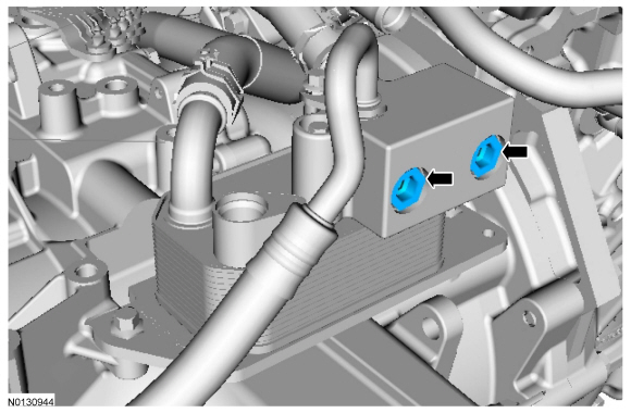
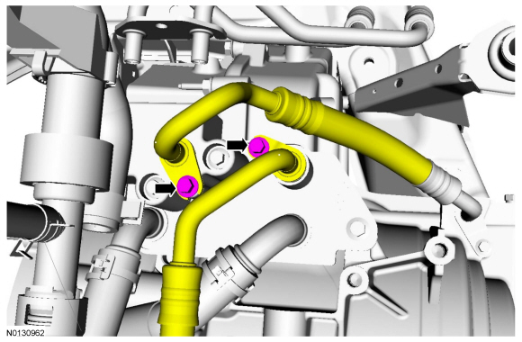
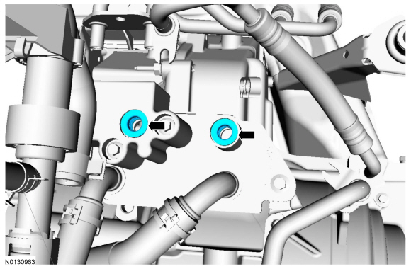
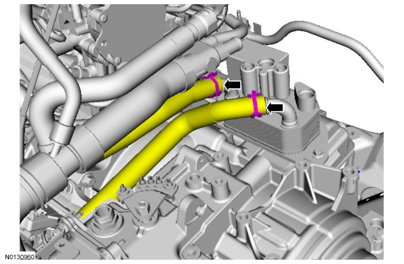
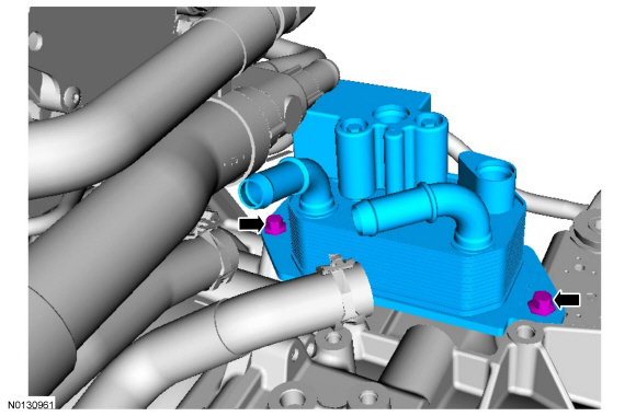
Installation
-
- Tighten to 25 Nm (18 lb-ft).
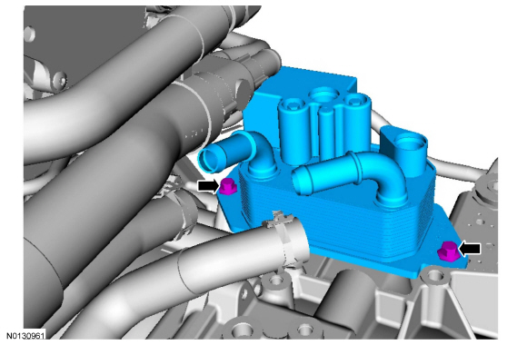
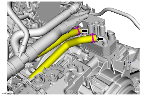
- Visual check. Apply the specified lubricant to the specified component.
Material: Motorcraft MERCON LV Automatic Transmission Fluid XT-10-QLVC.- Seal (7D258)
- Backing ring (7J324)
- Tighten to 11 Nm (97 lb-in).
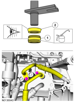
- Visual check. Apply the specified lubricant to the specified component.
Material: Motorcraft MERCON LV Automatic Transmission Fluid XT-10-QLVC.- Seal (7D258)
- Backing ring (7J324)
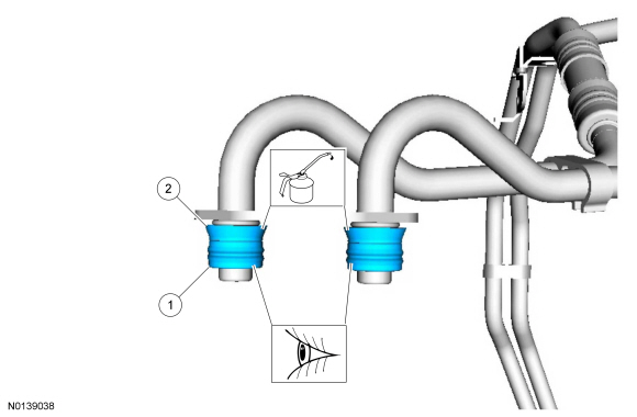
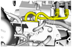
-
- Tighten to 25 Nm (18 lb-ft).
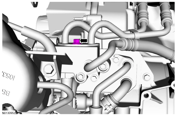
- Install the ACL outlet pipe. Refer to Section 303-12.
- Install the ACL. Refer to Section 303-12.
- Fill and bleed the cooling system. Refer to Section 303-03.
- Fill the transmission with fluid and verify correct operation. Refer to Section 307-01B.
Transmission Fluid Cooler Tubes
Special Tool(s)

Material

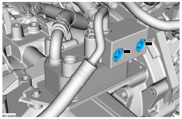
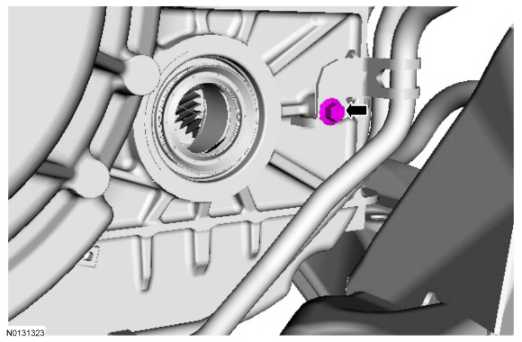
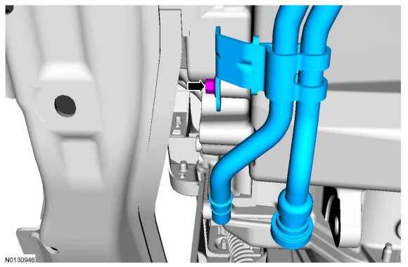
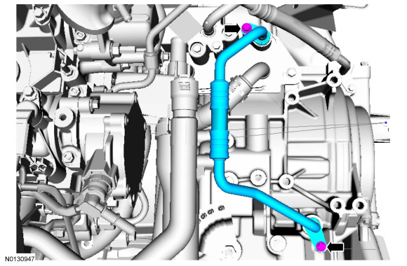
Removal
All transmission fluid cooler tubes
- With the vehicle in NEUTRAL, position it on a hoist. Refer to Section 100-02.
- Remove the ACL. Refer to Section 303-12.
- Remove the ACL outlet pipe. Refer to Section 303-12.
Front transmission fluid cooler tubes
- Remove the front bumper cover. Refer to Section 501-19.
All transmission fluid cooler tubes
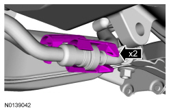
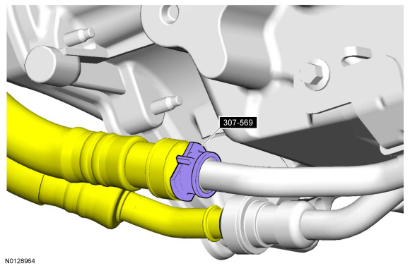
Front transmission fluid cooler tubes
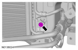
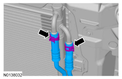
Rear transmission fluid cooler tubes
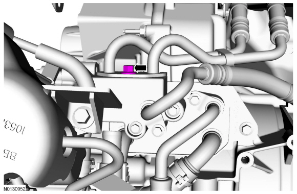
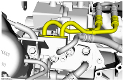
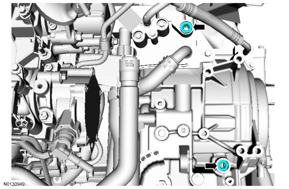
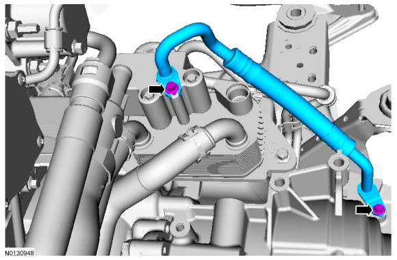
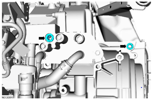
Installation
Rear transmission fluid cooler tubes
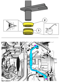
- Visual check. Apply the specified lubricant to the specified component.
Material: Motorcraft MERCON LV Automatic Transmission Fluid XT-10-QLVC.- Seal
- Backing ring
- Tighten to 11 Nm (97 lb-in).
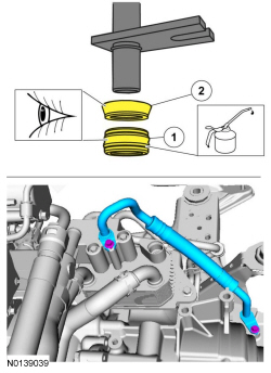
- Visual check. Apply the specified lubricant to the specified component.
Material: Motorcraft MERCON LV Automatic Transmission Fluid XT-10-QLVC.- Seal
- Backing ring
- Tighten to 11 Nm (97 lb-in).
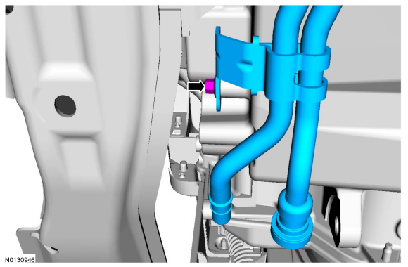
-
- Tighten to 11 Nm (97 lb-in).
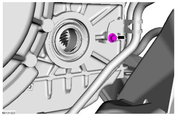
-
- Tighten to 11 Nm (97 lb-in).
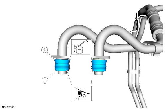
-
- Seal
- Backing ring
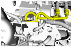
-
- Tighten to 25 Nm (18 lb-ft).
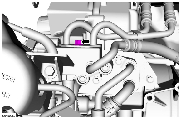
- Install the battery tray. Refer to Section 414-01.
Front transmission fluid cooler tubes
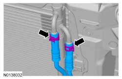
-
- Tighten to 6 Nm (53 lb-in).
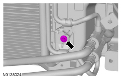
All transmission fluid cooler tubes
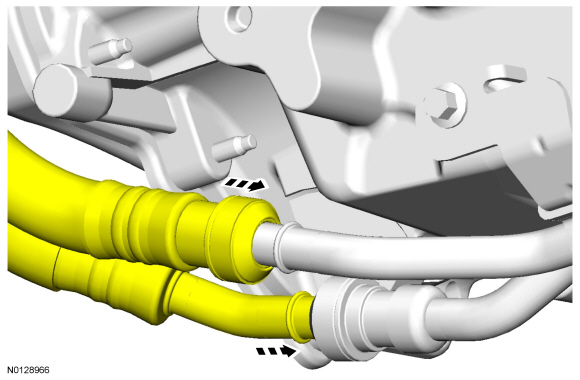
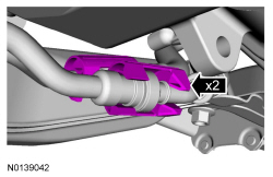
Front transmission fluid cooler tubes
- Install the front bumper cover. Refer to Section 501-19.
All transmission fluid cooler tubes
- Install the ACL outlet pipe. Refer to Section 303-12.
- Install the ACL. Refer to Section 303-12.
- Fill the transmission with fluid and verify correct operation. Refer to Section 307-01B.
Cooler Bypass Valve
Material

Removal
- With the vehicle in NEUTRAL, position it on a hoist. Refer to Section 100-02.
- Drain the engine cooling system. Refer to Section 303-03.
- Remove the ACL. Refer to Section 303-12.
- Remove the ACL outlet pipe. Refer to Section 303-12.
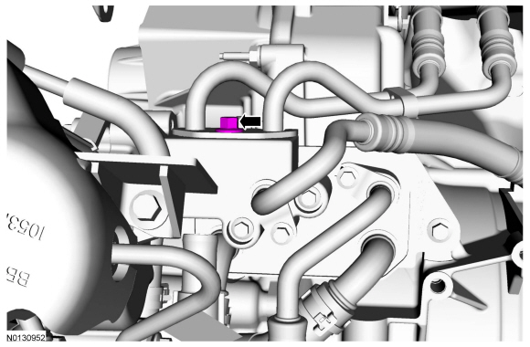
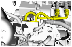
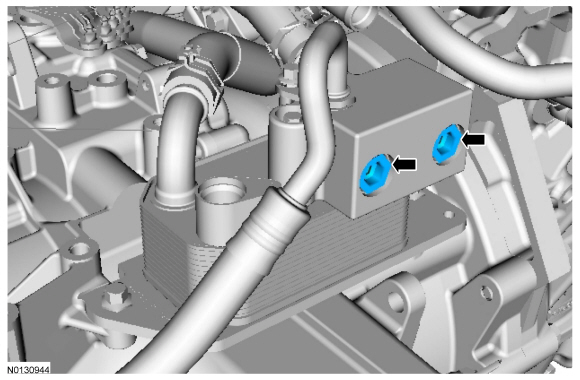
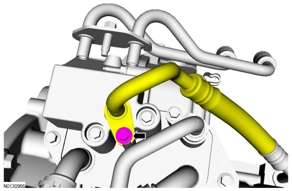
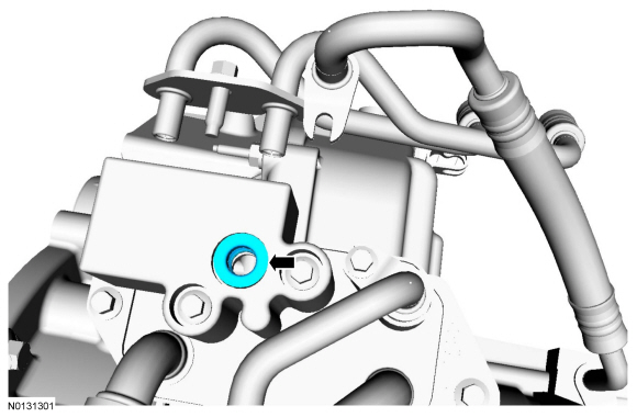
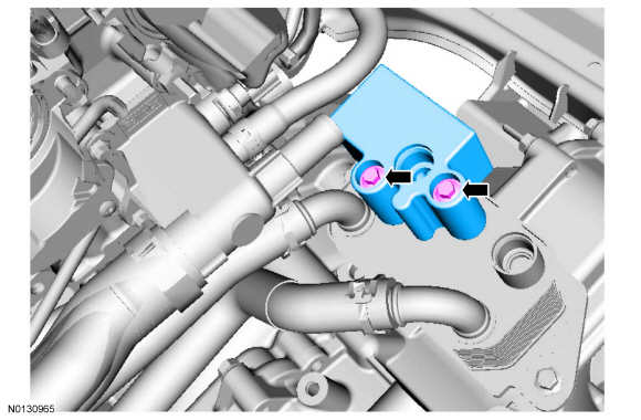
Installation
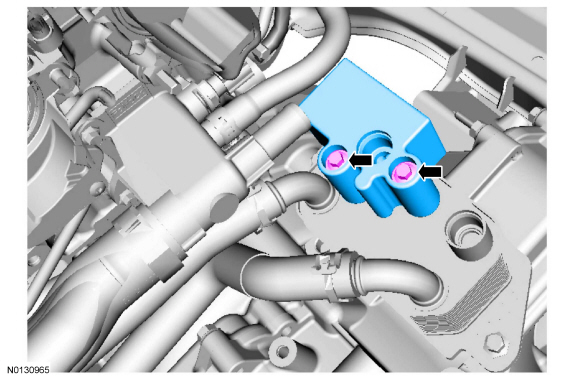
-
- Tighten to 16 Nm (142 lb-in).
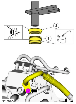
- Visual check. Apply the specified lubricant to the specified component.
Material: Motorcraft MERCON LV Automatic Transmission Fluid XT-10-QLVC.- Seal
- Backing ring
- Tighten to 11 Nm (97 lb-in).
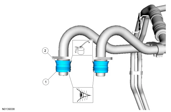
- Visual check. Apply the specified lubricant to the specified component.
Material: Motorcraft MERCON LV Automatic Transmission Fluid XT-10-QLVC.- Seal
- Backing ring
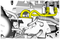
-
- Tighten to 25 Nm (18 lb-ft).
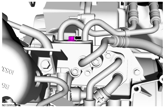
- Install the ACL outlet pipe. Refer to Section 303-12.
- Install the ACL. Refer to Section 303-12.
- Fill the transmission with fluid and verify correct operation. Refer to Section 307-01B.
 Transaxle/Transmission Cooling - 6F50/6F55
SPECIFICATIONS
General Specifications
Material
a 6F50 transmission.
b 6F55 transmission.
Torque Specifications
a 3.5L GTDI
b 3.5L Ti-VCT
DESCRIPTION AND OPERATION
Transaxle Cool ...
Other materials:
Data recording
Service Data Recording
Service data recorders in your vehicle are capable of collecting and
storing diagnostic information about your vehicle. This potentially
includes information about the performance or status of various systems
and modules in the vehicle, such as engine, throttle, steering o ...
Capacities and Specifications
Engine Drivebelt Routing
3.5L V6 engine
3.5L V6 SHO engine
2.0L EcoBoost engine
...
Diagnosis and Testing
Information and Entertainment System
Special Tool(s)
Preliminary Inspection
Before diagnosing or repairing the audio system, verify the audio system
module(s) pass the network test.
DTC Chart(s)
NOTE: For SYNC related concerns, REFER to the SYNC Symptom Chart before
connecting the scan to ...

