SPECIFICATIONS
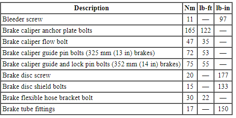
Torque Specifications
REMOVAL AND INSTALLATION
Brake Pads - 325 mm (13 in) Brakes
Material

Removal
WARNING: Before beginning any service procedure in this section, refer to Safety Warnings in Section 100-00. Failure to follow this instruction may result in serious personal injury.
NOTICE: Do not spill brake fluid on painted or plastic surfaces or damage to the surface may occur. If brake fluid is spilled onto a painted or plastic surface, immediately wash the surface with water.
NOTICE: Do not allow grease, oil, brake fluid or other contaminants to contact the pad lining material, or damage to components may occur. Do not install contaminated pads.
NOTE: Removal steps in this procedure may contain installation details.
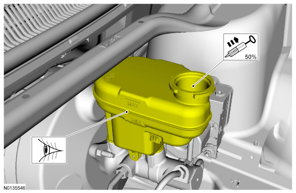
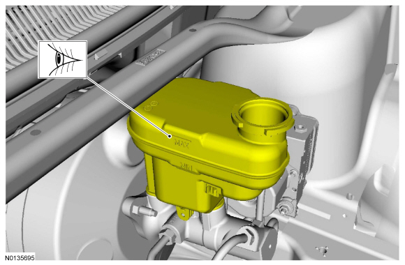
- NOTE: The master cylinder reservoir should be half full to avoid
overflow when the brake caliper pistons are retracted.
Visual check. Extract the fluid with a syringe.
- Remove the wheel and tire. For additional information, REFER to Section 204-04.
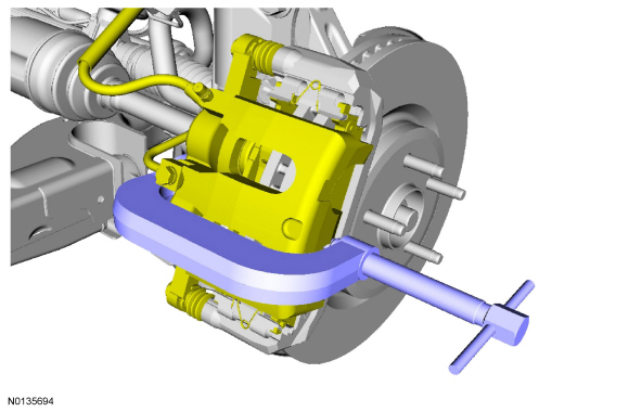
- NOTICE: Do not allow the brake caliper to hang from the brake
flexible hose and or damage to the hose may occur.
NOTICE: Make sure the brake caliper guide pin bolts are clean and free of debris or a binding condition may occur.
NOTICE: Do not allow the brake flexible hose to get twisted when the caliper is repositioned on the brake caliper anchor plate or damage to the hose may occur.
Relocate and support the component.- To install, tighten to 72 Nm (53 lb-ft).
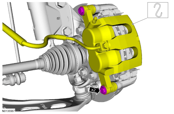
- NOTE: During installation, the coil in the center of the wire spreader spring must lie against the anchor plate and must not be in the raised position. If the coil in the center of the wire spreader spring does not rest against the caliper anchor plate, the spring is installed incorrectly and must be repositioned.
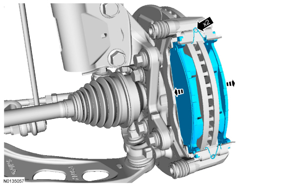
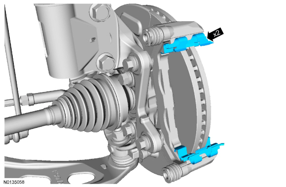
- NOTICE: Make sure the caliper pin boots are correctly seated
to prevent corrosion to the guide pins.
Visual check.
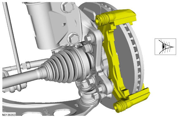
Installation
- NOTE: If installing new brake pads, make sure to install all new
hardware and lubricant supplied with the brake pad kit. Refer to the brake
pad instruction sheet when applying lubricant.
To install, reverse the removal procedure.
- Visual check.
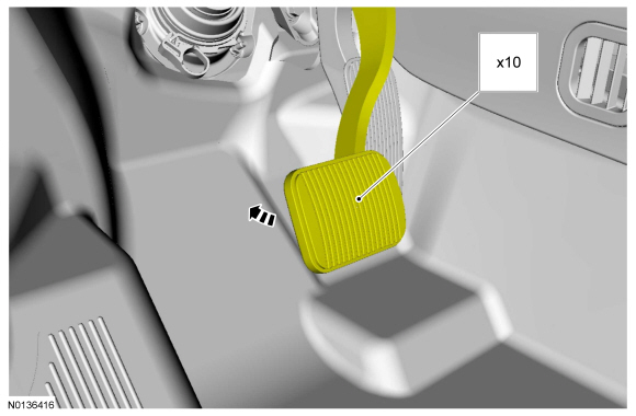
Brake Pads - 352 mm (14 in) Brakes
Material

Removal
WARNING: Before beginning any service procedure in this section, refer to Safety Warnings in Section 100-00. Failure to follow this instruction may result in serious personal injury.
NOTICE: Do not spill brake fluid on painted or plastic surfaces or damage to the surface may occur. If brake fluid is spilled onto a painted or plastic surface, immediately wash the surface with water.
NOTICE: Do not allow grease, oil, brake fluid or other contaminants to contact the pad lining material, or damage to components may occur. Do not install contaminated pads.
NOTE: Removal steps in this procedure may contain installation details.
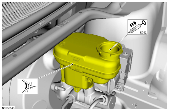
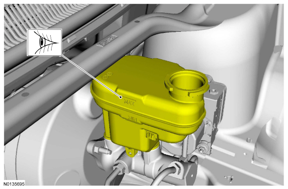
- NOTE: The master cylinder reservoir should be half full to avoid
overflow when the brake caliper pistons are retracted.
Visual check. Extract the fluid with a syringe.
- Remove the wheel and tire. For additional information, REFER to Section 204-04.
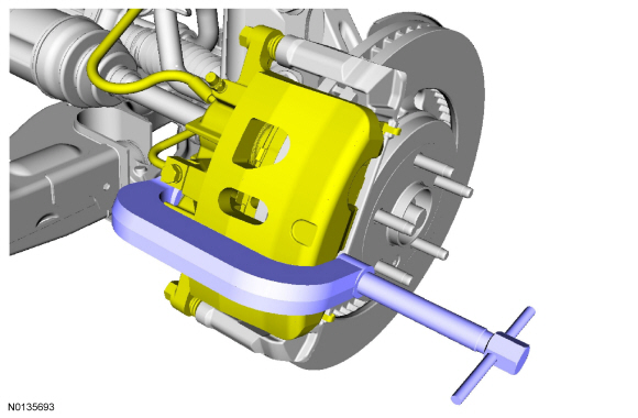
- NOTICE: Do not allow the brake caliper to hang from the brake
flexible hose and or damage to the hose may occur.
NOTICE: Make sure the brake caliper guide pin bolts are clean and free of debris or a binding condition may occur.
NOTICE: Do not allow the brake flexible hose to get twisted when the caliper is repositioned on the brake caliper anchor plate or damage to the hose may occur.
Relocate and support the component.- To install, tighten to 75 Nm (55 lb-ft).
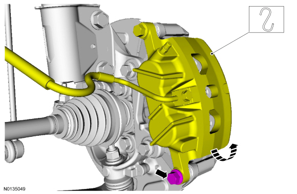
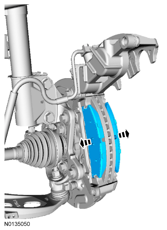
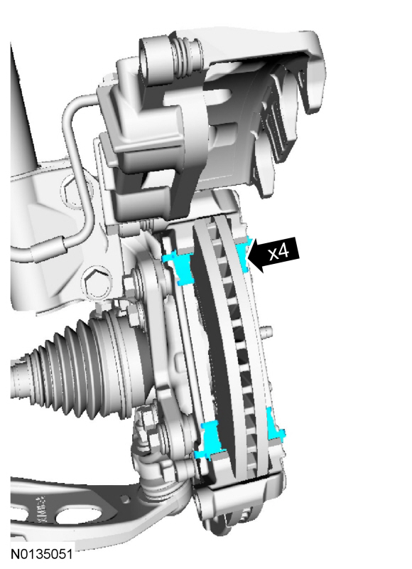
- NOTICE: Make sure the caliper pin boots are correctly seated
to prevent corrosion to the guide pins.
Visual check.
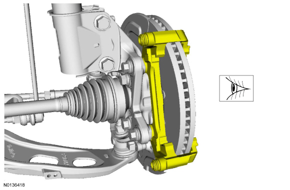
Installation
- NOTE: If installing new brake pads, make sure to install all new
hardware and lubricant supplied with the brake pad kit. Refer to the brake
pad instruction sheet when applying lubricant.
To install, reverse the removal procedure.
- Visual check.
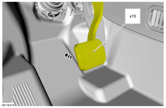
Brake Caliper
Material

Removal
WARNING: Before beginning any service procedure in this section, refer to Safety Warnings in Section 100-00. Failure to follow this instruction may result in serious personal injury.
NOTICE: Do not spill brake fluid on painted or plastic surfaces or damage to the surface may occur. If brake fluid is spilled onto a painted or plastic surface, immediately wash the surface with water.
NOTICE: Do not allow grease, oil, brake fluid or other contaminants to contact the pad lining material, or damage to components may occur. Do not install contaminated pads.
NOTE: Removal steps in this procedure may contain installation details.
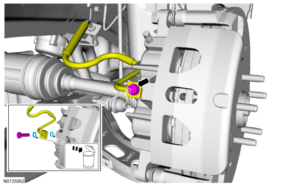
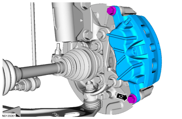
NOTE: 352 mm (14 in) brakes shown, 325 mm (13 in) brakes similar.
- Discard the specified component. Follow local disposal regulations.
- To install, tighten to 47 Nm (35 lb-ft).
- NOTICE: Make sure the brake caliper guide pin bolts are clean
and free of debris or a binding condition may occur.
NOTICE: Make sure the caliper pin boots are correctly seated to prevent corrosion to the guide pins.
- 325 mm (13 in) brakes: To install, tighten to 72 Nm (53 lb-ft).
- 352 mm (14 in) brakes: To Install, tighten to 75 Nm (55 lb-ft).
Installation
- To install, reverse the removal procedure.
- Lubricate the brake caliper flow bolt threads and new washers with clean specified brake fluid before installing the brake caliper flow bolt into the brake caliper.
- Bleed the brake caliper. For additional information, REFER to Section 206-00 for Component Bleeding.
Brake Caliper Anchor Plate
Removal
WARNING: Before beginning any service procedure in this section, refer to Safety Warnings in Section 100-00. Failure to follow this instruction may result in serious personal injury.
NOTE: Removal steps in this procedure may contain installation details.
All vehicles
- Remove the brake pads. For additional information, refer to Brake Pads - 352 mm (14 in) Brakes or Brake Pads - 325 mm (13 in) Brakes in this section.
Vehicles with 352 mm (14 in) brakes
- Relocate and support the component.
- To install, tighten to 75 Nm (55 lb-ft).
All vehicles
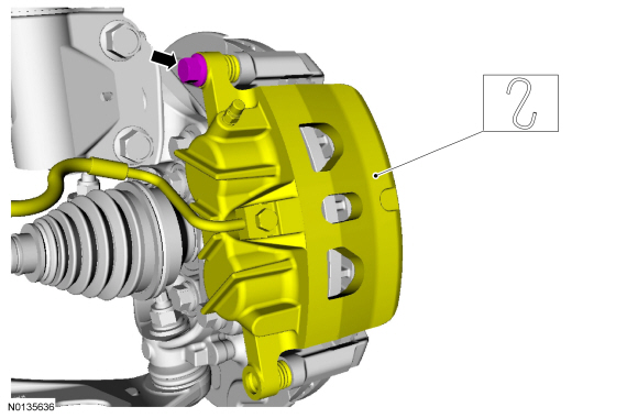
- NOTE: 352 mm (14 in) brakes shown, 325 mm (13 in) brakes similar.
Discard the specified component. Follow local disposal regulations.
- To install, tighten to 165 Nm (122 lb-ft).
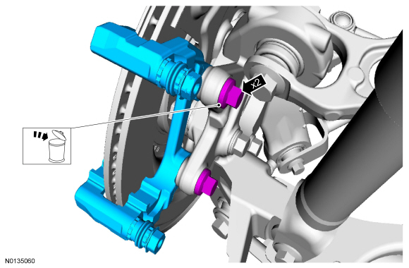
Installation
- To install, reverse the removal procedure.
Brake Disc
Material

Removal
WARNING: Before beginning any service procedure in this section, refer to Safety Warnings in Section 100-00. Failure to follow this instruction may result in serious personal injury.
NOTE: Removal steps in this procedure may contain installation details.
NOTE: 352 mm (14 in) brakes shown, 325 mm (13 in) brakes similar.
- Remove the wheel and tire. For additional information, REFER to Section 204-04.
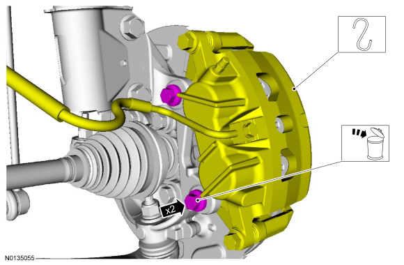
- NOTICE: Do not allow the brake caliper to hang from the brake
flexible hose or damage to the hose may occur.
Relocate and support the component. Discard the specified component. Follow local disposal regulations.
- To install, tighten the new bolts to 165 Nm (122 lb-ft).
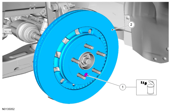
- NOTE: If necessary, thread a M10 bolt into the brake disc removal
hole and tighten to press the disc off the hub.
Discard the specified component. Follow local disposal regulations.
- To install, tighten the new screw to 20 Nm (177 lb-in).
Installation
- Visual check. Wire brush. Clean the specified component with the specified material.
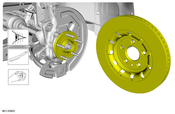
- To install, reverse the removal procedure.
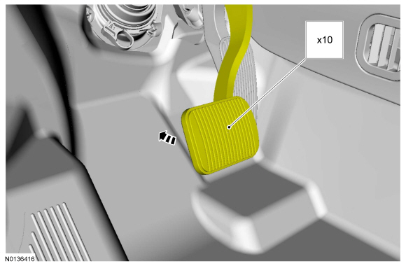
Brake Disc Shield
Removal
WARNING: Before beginning any service procedure in this section, refer to Safety Warnings in Section 100-00. Failure to follow this instruction may result in serious personal injury.
NOTE: Removal steps in this procedure may contain installation details.
NOTE: 352 mm (14 in) brakes shown, 325 mm (13 in) brakes similar.
- Remove the brake disc. For additional information, refer to Brake Disc in this section.
-
- To install, tighten to 15 Nm (133 lb-in).
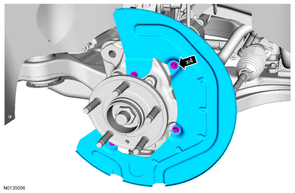
Installation
- To install, reverse the removal procedure.
Brake Flexible Hose
Material

Removal
WARNING: Before beginning any service procedure in this section, refer to Safety Warnings in Section 100-00. Failure to follow this instruction may result in serious personal injury.
NOTICE: Do not spill brake fluid on painted or plastic surfaces or damage to the surface may occur. If brake fluid is spilled onto a painted or plastic surface, immediately wash the surface with water.
NOTICE: Do not allow grease, oil, brake fluid or other contaminants to contact the pad lining material, or damage to components may occur. Do not install contaminated pads.
NOTE: Removal steps in this procedure may contain installation details.
NOTE:
- With the vehicle in NEUTRAL, position it on a hoist. For additional information, REFER to Section 100-02.
- NOTICE: Make sure to protect the brake pads from contamination
from the brake fluid during the brake flexible hose installation and the
brake caliper bleeding.
- To install, tighten the brake tube fiting to 17 Nm (150 lb-in).
- To install, tighten the brake flexible hose bracket bolt to 30 Nm (22 lb-ft).
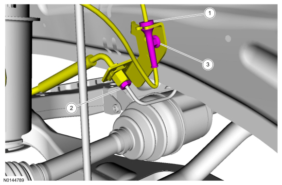
- Discard the specified component. Follow local disposal regulations.
- To install, tighten to 47 Nm (35 lb-ft).
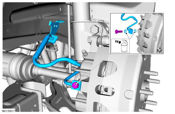
Installation
- To install, reverse the removal procedure.
- Lubricate the brake caliper flow bolt threads and new washers with clean brake fluid before installing the brake caliper flow bolt into the brake caliper.
- Bleed the brake caliper. For additional information, REFER to Section 206-00 for Component Bleeding.
 Brake System - General Information
SPECIFICATIONS
Material
General Specifications
Torque Specifications
DIAGNOSIS AND TESTING
Principles of Operation
Brake System
Applying the brake pedal uses lever action to push a rod into the bra ...
 Rear Disc Brake
SPECIFICATIONS
Torque Specifications
REMOVAL AND INSTALLATION
Brake Pads
Special Tool(s)
Material
Removal
WARNING:
Before beginning any service procedure in this section, refer to Safety Warnings ...
Other materials:
In-Vehicle Repair
Upper Intake Manifold
Removal
NOTICE: If the engine is repaired or replaced because of upper
engine failure, typically including valve or piston damage, check the intake
manifold for metal debris. If metal debris is found, install a new intake
manifold. Failure to follow these instructions c ...
Temporary mobility kit
Note: The temporary mobility kit sealant compound in the canister is
to
be used for one tire only. See your Ford authorized dealer for additional
replacement sealant canisters.
Your vehicle may be equipped with a temporary mobility kit (located in
the spare tire well in the trunk). The tempo ...
Disassembly and Assembly of Subassemblies
Cylinder Head
Special Tool(s)
Material
Disassembly
NOTICE: During engine repair procedures, cleanliness is extremely
important. Any foreign material, including any material created while cleaning
gasket surfaces, that enters the oil passages, coolant passages or the oil pan
can cause en ...
