SPECIFICATIONS
Torque Specifications
REMOVAL AND INSTALLATION
Brake Pads
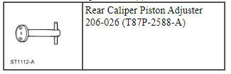
Special Tool(s)
Material
Removal
WARNING: Before beginning any service procedure in this section, refer to Safety Warnings in Section 100-00. Failure to follow this instruction may result in serious personal injury.
NOTICE: Do not spill brake fluid on painted or plastic surfaces or damage to the surface may occur. If brake fluid is spilled onto a painted or plastic surface, immediately wash the surface with water.
NOTICE: Do not allow grease, oil, brake fluid or other contaminants to contact the pad lining material, or damage to components may occur. Do not install contaminated pads.
NOTE: 352 mm (14 in) brakes shown, 325 mm (13 in) brakes similar.
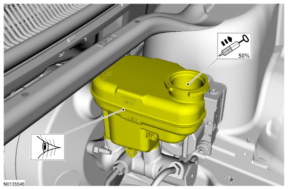
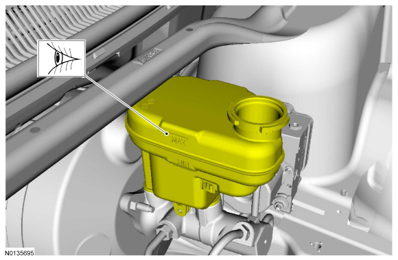
- NOTE: The master cylinder reservoir should be half full to avoid
overflow when the brake caliper pistons are retracted.
Visual check. Extract the fluid with a syringe.
- Remove the wheel and tire. For additional information, REFER to Section 204-04.
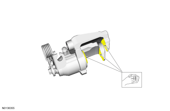
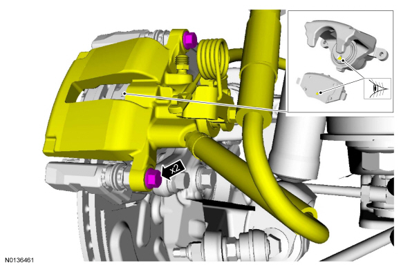
- NOTE: Use hand force and a rocking motion to separate the brake
caliper from the brake pads.
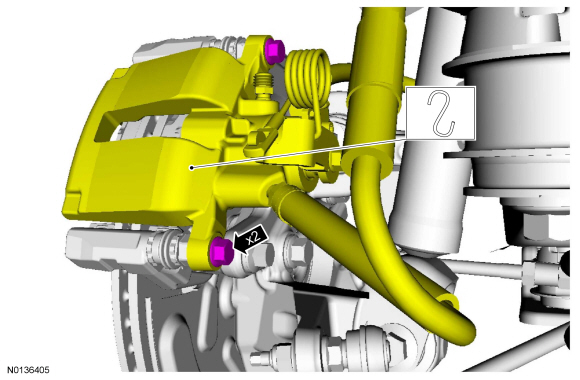
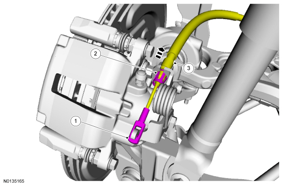
NOTICE: Care must be taken when servicing rear brake components without disconnecting the parking brake cable from the brake caliper lever. Carefully position the caliper aside using a suitable support or damage to the parking brake cable end fittings may occur.
NOTICE: Do not allow the caliper to hang from the brake hose or damage to the hose may occur.
Relocate and support the component.
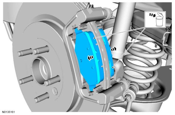
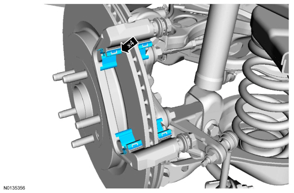
- NOTICE: Brake pads with adhesive on the insulator are one-time
use only. When the brake pads are separated from the brake caliper, new
brake pads must be installed to prevent brake noise and shudder.
NOTE: For 352 mm (14 in) brakes, note the orientation of the inner and outer brake pads for reference during installation. Outer brake pads will have OTR stamped on the top of the backing. Inner brake pads (Police vehicles only) will have INR stamped on the top of the backing.
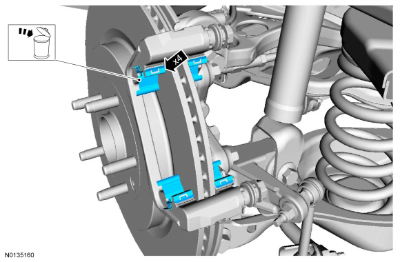
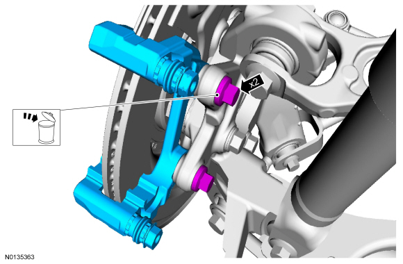
Discard the specified component. Follow local disposal regulations.
- Discard the specified component. Follow local disposal regulations.
Installation
- Visual check.
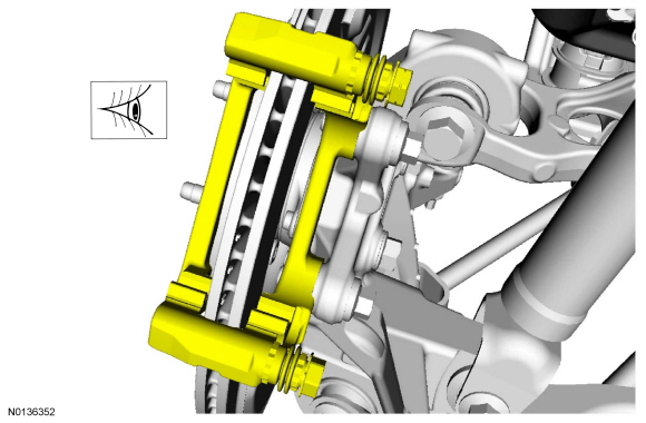
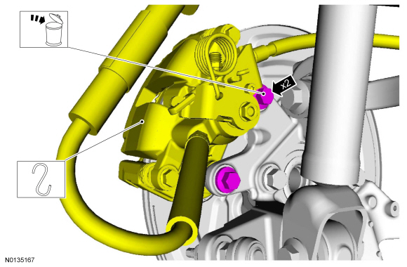
- NOTICE: Clean all residual pad adhesive from the brake caliper
piston and the finger area of the brake caliper or brake noise may occur.
Clean the specified component with the specified material.
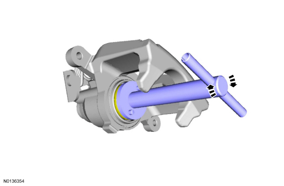
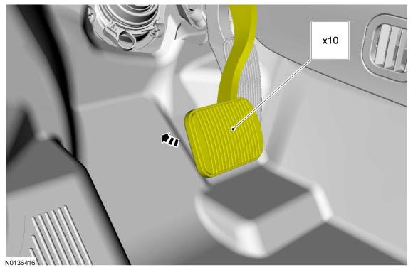
- NOTE: A moderate to heavy force toward the caliper piston must be
applied. If sufficient force is not applied, the internal park brake
mechanism clutch cone will not engage and the piston will not compress.
Special tool(s): Rear Caliper Piston Adjuster 206-026
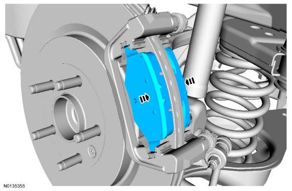
- NOTICE: Install the inner and outer brake pads in the correct position or uneven brake pad wear and/or component damage may occur.
- NOTICE: Make sure the brake flexible hose does not become
twisted. A twisted brake hose may make contact with other components causing
damage to the hose.
Visual check.
- Tighten to 33 Nm (24 lb-ft).
Brake Caliper Anchor Plate
Removal
WARNING: Before beginning any service procedure in this section, refer to Safety Warnings in Section 100-00. Failure to follow this instruction may result in serious personal injury.
NOTE: Removal steps in this procedure may contain installation details.
NOTE: 352 mm (14 in) brakes shown, 325 mm (13 in) brakes similar.
- Remove the brake pads. For additional information, refer to Brake Pads in this section.
- Discard the specified component. Follow local disposal regulations.
- To install, tighten to 103 Nm (76 lb-ft).
Installation
- To install, reverse the removal procedure.
Brake Caliper
Removal
WARNING: Before beginning any service procedure in this section, refer to Safety Warnings in Section 100-00. Failure to follow this instruction may result in serious personal injury.
NOTICE: Do not spill brake fluid on painted or plastic surfaces or damage to the surface may occur. If brake fluid is spilled onto a painted or plastic surface, immediately wash the surface with water.
NOTE: Removal steps in this procedure may contain installation details.
NOTE: 352 mm (14 in) brakes shown, 325 mm (13 in) brakes similar.
- Release the parking brake cable tension. For additional information, REFER to Section 206-05.
- Remove the brake flexible hose. For additional information, refer to Brake Flexible Hose in this section.
- NOTICE: When the brake pads are separated from the brake
caliper, new brake pads must be installed to prevent brake noise and
shudder. The brake pads are one-time-use only.
Remove and discard the brake pads. For additional information, refer to Brake Pads in this section.
Installation
- NOTICE: During installation, make sure that the brake flexible
hose does not become twisted or damage to hose may occur.
NOTE: If equipped, verify correct installation of the brake flexible hose protective sleeve and tie strap.
To install, reverse the removal procedure.- Bleed the caliper. For additional information, refer to Component Bleeding in REFER to Section 206-00.
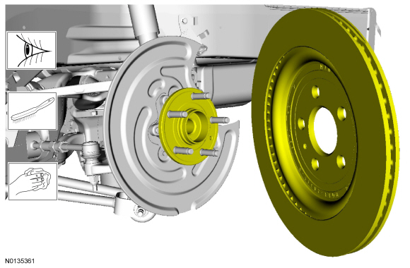
Brake Disc
Removal
WARNING: Before beginning any service procedure in this section, refer to Safety Warnings in Section 100-00. Failure to follow this instruction may result in serious personal injury.
NOTE: Removal steps in this procedure may contain installation details.
NOTE: 352 mm (14 in) brakes shown, 325 mm (13 in) brakes similar.
- Remove the wheel and tire. For additional information, REFER to Section 204-04.
- NOTICE: Do not allow the caliper to hang from the brake hose
or damage to the hose can occur.
NOTICE: Care must be taken when servicing rear brake components without disconnecting the parking brake cable from the brake caliper lever. Carefully position the caliper aside using a suitable support or damage to the parking brake cable end fittings may occur.
Relocate and support the component. Discard the specified component. Follow local disposal regulations.- To install, tighten the new bolts to 150 Nm (111 lb-ft).
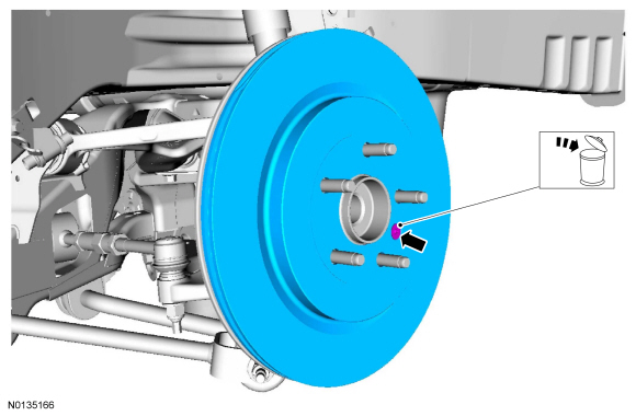
- NOTE: If necessary, thread a M10 bolt into the brake disc removal
hole and tighten to press the disc off the hub.
Discard the specified component. Follow local disposal regulations.
- To install, tighten the new screw to 20 Nm (177 lb-in).
Installation
- Visual check. Wire brush. Clean the specified component with the specified material.
- To install, reverse the removal procedure.

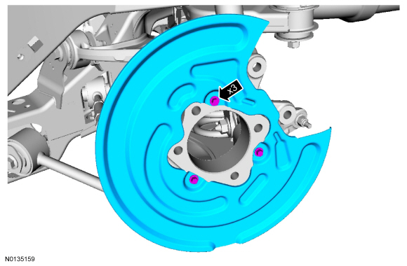
Brake Disc Shield
Removal
WARNING: Before beginning any service procedure in this section, refer to Safety Warnings in Section 100-00. Failure to follow this instruction may result in serious personal injury.
NOTE: Removal steps in this procedure may contain installation details.
NOTE: 352 mm (14 in) brakes shown, 325 mm (13 in) brakes similar.
- Remove the wheel hub and bearing. For additional information, REFER to Section 204-02.
-
- To install, tighten to 15 Nm (133 lb-in).
Installation
- To install, reverse the removal procedure.
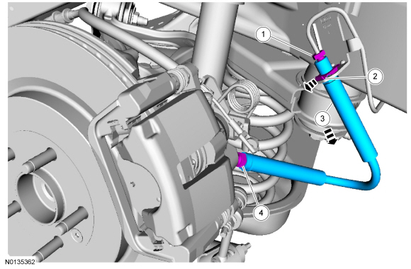
Brake Flexible Hose
Removal
WARNING: Before beginning any service procedure in this section, refer to Safety Warnings in Section 100-00. Failure to follow this instruction may result in serious personal injury.
NOTICE: Do not allow the brake fluid to come in contact with the adhesive backing on the brake pads. This may prevent the brake pad adhesive surface from bonding with the brake caliper. If brake fluid is spilled onto the brake pads, install new pads.
NOTICE: Do not spill brake fluid on painted or plastic surfaces or damage to the surface may occur. If brake fluid is spilled onto a painted or plastic surface, immediately wash the surface with water.
NOTE: Removal steps in this procedure may contain installation details.
NOTE: 352 mm (14 in) brakes shown, 325 mm (13 in) brakes similar.
- With the vehicle in NEUTRAL, position it on a hoist. For additional information, REFER to Section 100-02.
-
- To install, tighten the brake tube fitting to 17 Nm (150 lb-in).
- To install, tighten the brake flexible hose threaded fitting to 30 Nm (20 lb-ft).
Installation
- NOTE: If equipped, verify correct installation of the brake
flexible hose protective sleeve and tie strap.
To install, reverse the removal procedure.
- Bleed the brake caliper. For additional information, refer to Component Bleeding in REFER to Section 206-00.
 Front Disc Brake
SPECIFICATIONS
Torque Specifications
REMOVAL AND INSTALLATION
Brake Pads - 325 mm (13 in) Brakes
Material
Removal
WARNING:
Before beginning any service procedure in this section, refer to Safety Wa ...
 Parking Brake and Actuation
SPECIFICATIONS
Torque Specifications
DESCRIPTION AND OPERATION
Parking Brake
The parking brake system consists of the following components:
Parking brake control and front cable assembly
Rear park ...
Other materials:
Cleaning the engine
Engines are more efficient when they are clean because grease and dirt
buildup keep the engine warmer than normal.
When washing:
• Take care when using a power washer to clean the engine. The
high-pressure fluid could penetrate the sealed parts and cause
damage.
• Do not spray a hot en ...
General Procedures
Valve Clearance Check
Remove the RH fender splash shield. For additional information, refer
to Section 501-02.
Remove the valve cover. For additional information, refer to Valve
Cover in this section.
NOTE: Turn the engine clockwise only, and only use the crankshaft
...
Diagnosis and Testing
Rear View Mirrors - Exterior
DTC Chart(s)
Diagnostics in this manual assume a certain skill level and knowledge of
Ford-specific diagnostic practices. REFER to Section 100-00 for information
regarding these diagnostic practices.
DDM DTC Chart
DSM DTC Chart
Symptom Chart(s)
Di ...
