Exterior Mirror
Removal and Installation
NOTE: Do not remove the exterior mirror assembly when repairing an individual part. Individual components can be installed without removing the exterior mirror.
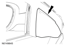
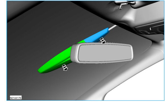
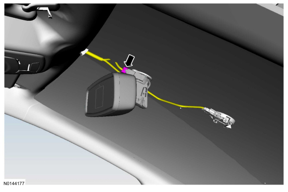
- Remove the sail panel.
- Pull outward on the sail panel to release the retaining clips.
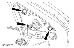
- Disconnect the exterior mirror electrical connector.
- Remove the 2 exterior mirror nuts and bolt.
- To install, tighten to 9 Nm (80 lb-in).
- Remove the exterior mirror.
- To install, reverse the removal procedure.
Exterior Mirror Glass
Removal
- Position the exterior mirror glass to the full upward and inward position.
- WARNING:
Place a shop towel between the hands and the exterior mirror glass for
protection in case of glass breakage during mirror service. Failure to
follow this instruction may result in serious personal injury.
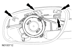
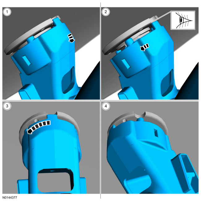
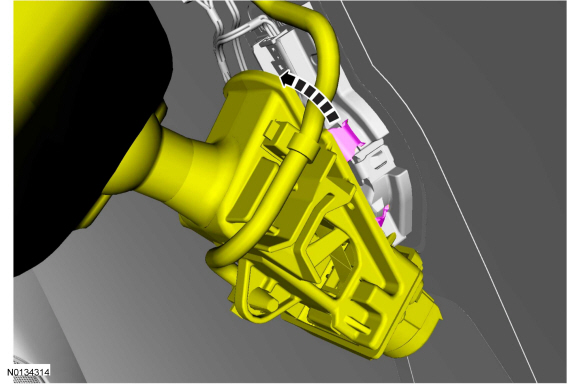
NOTE: LH mirror and motor removed from the housing and viewed from the back to show location of clips and placement of screwdriver.
Remove the exterior mirror glass using a screwdriver to release the tabs starting at the lower outboard side of mirror and continuing around the mirror until all 4 tabs are released.
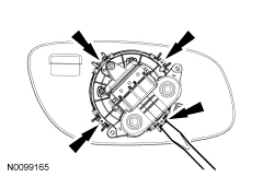
- Disconnect the electrical connectors.
Installation
- Connect the electrical connectors.
- WARNING:
Place a shop towel between the hands and the exterior mirror glass for
protection in case of glass breakage during mirror service. Failure to
follow this instruction may result in serious personal injury.
NOTE: An audible click will be heard during installation.
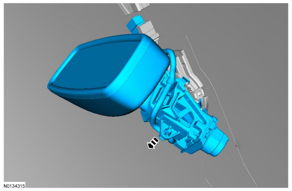
Install the exterior mirror glass by pressing firmly in the center of the exterior glass until it snaps onto the exterior mirror motor.
Exterior Mirror Motor
Removal and Installation
- Remove the exterior mirror glass. For additional information, refer to Exterior Mirror Glass in this section.
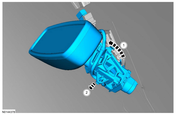
- Remove the 3 exterior mirror motor screws.
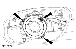
- Remove the exterior mirror motor.
- Disconnect the electrical connector(s).
- To install, reverse the removal procedure.
Exterior Mirror Cover
Removal and Installation
- Remove the exterior mirror glass. For additional information, refer to Exterior Mirror Glass in this section.
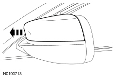
- Release the 4 exterior mirror cover retaining tabs.
- Remove the exterior mirror cover.
- Pull outward on the exterior mirror cover.
- To install, reverse the removal procedure.
Interior Rear View Mirror
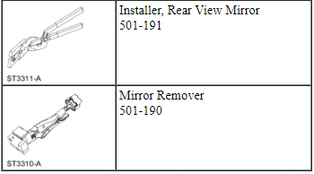
Special Tool(s)
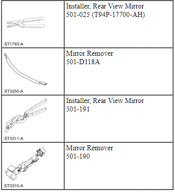
Mirror Identification
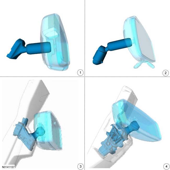
- Mirror type 1
- Mirror type 2
- Mirror type 3
- Mirror type 4
Removal
Mirror Type 1
NOTICE: The windshield must be at room temperature. Otherwise, damage to the windshield glass may occur.
NOTE:
 Click
here to view a video version of this procedure.
Click
here to view a video version of this procedure.
- If equipped.


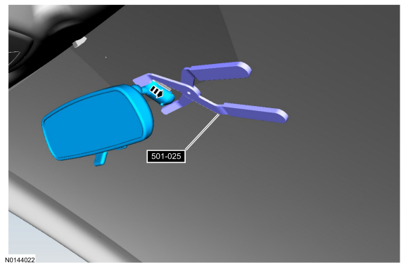
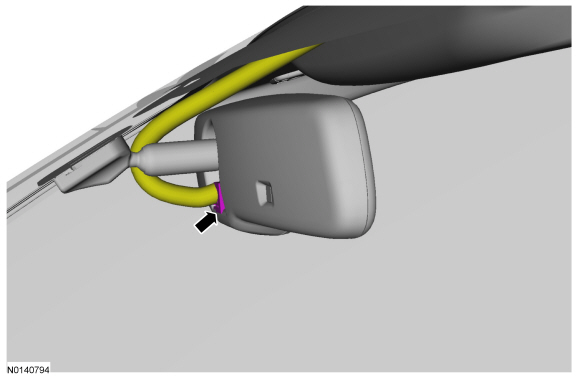
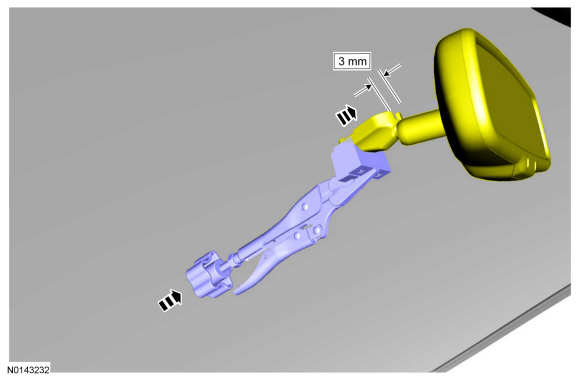
- NOTICE: Make sure the Mirror Remover is fully inserted into the interior rear view mirror mount access hole. Otherwise, damage to the windshield glass may occur.

- Using a closed hand, bump the adjustment handle of the Mirror Remover to slide the mirror upward on the mirror mount.
Mirror Type 2
Mirror Type 3
Mirror Type 4


- NOTICE: To prevent damage to the mirror or base, rotate the
mirror base with hands only do not use tools.
NOTICE: To prevent damage to the mirror wiring, do not rotate the mirror head beyond 180 degrees.
Installation
Mirror Type 1
NOTE:
 Click
here to view a video version of this procedure.
Click
here to view a video version of this procedure.
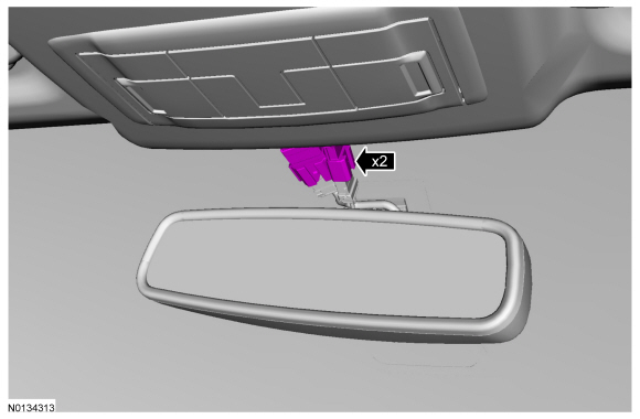
- Slide the interior rear view mirror mount over the windshield bracket from the top.

- NOTE: An audible click will be heard as the mirror fully seats.

- If equipped.

- If equipped, check the compass zone and calibration. Refer to Section 413-01.
Mirror Type 2
- If equipped with a compass module which requires calibration, check the compass zone adjustment and calibration. Refer to General Procedures in Section 413-01.
Mirror Type 3
- To install, reverse the removal procedure.
Mirror Type 4
- To install, reverse the removal procedure.
- If a new mirror has been installed, download the IPM-A configuration information from the scan tool to the new IPM-A.
- If the vehicle is equipped with lane departure and a new mirror has been installed, perform camera alignment using a scan tool.
Interior Rear View Mirror - Auto-Dimming
Special Tool(s)
Removal
NOTICE: The windshield must be at room temperature. Otherwise, damage to the windshield glass may occur.
NOTE:
 Click
here to view a video version of this procedure.
Click
here to view a video version of this procedure.
- If equipped.
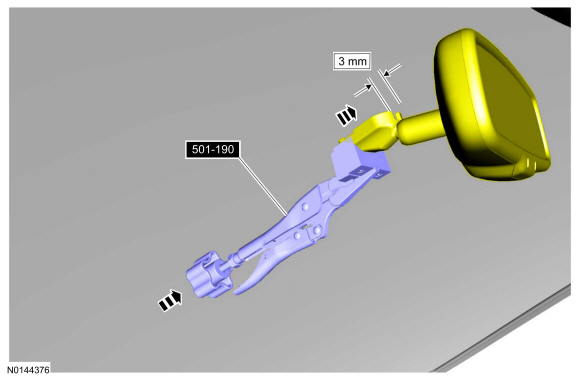
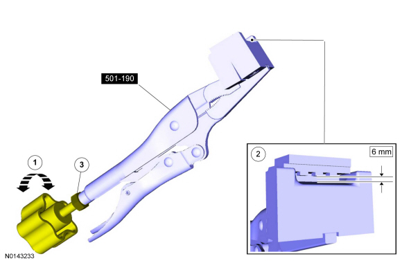
- If using mirror removal tool 501-190.
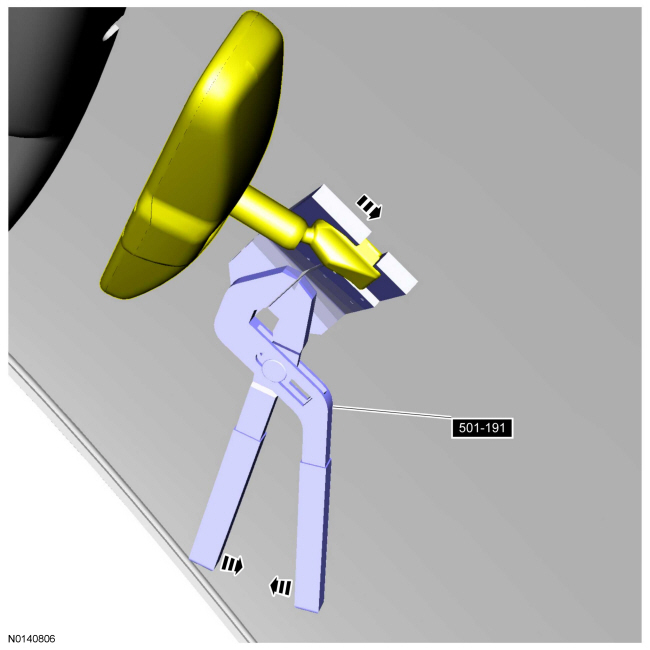
- NOTICE: Make sure the Mirror Remover is fully inserted into the interior rear view mirror mount access hole. Otherwise, damage to the windshield glass may occur.
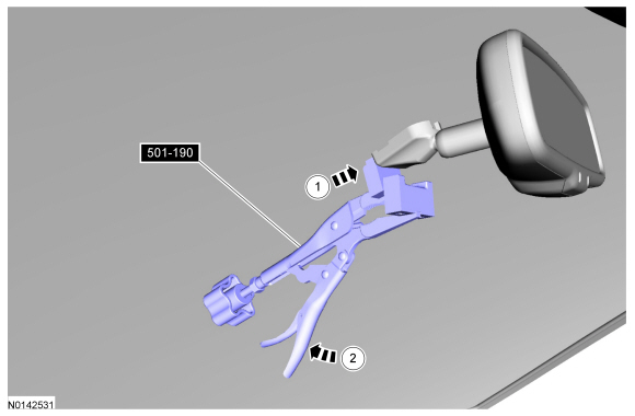
- Using a closed hand, bump the adjustment handle of the Mirror Remover to
slide the mirror upward on the mirror mount.
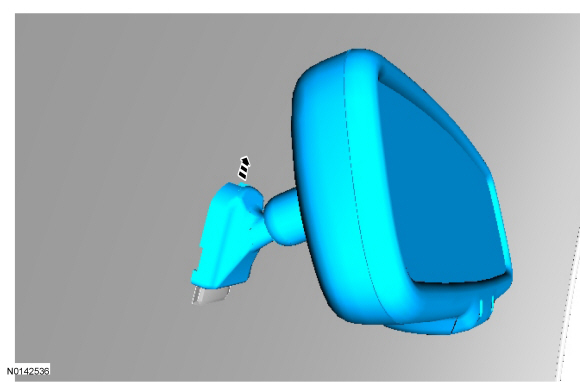
- Remove the Mirror Remover.
- NOTE: If the mirror does not easily slide off the mirror mount, gently rock the mirror while sliding upward to release the mirror.

Installation
NOTE:
 Click
here to view a video version of this procedure.
Click
here to view a video version of this procedure.
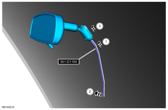
- Slide the interior rear view mirror mount over the windshield bracket from the top.

- NOTE: An audible click will be heard as the mirror fully seats.
Using the Rear View Mirror Installer, press the interior rear view mirror mount downward along the windshield bracket until the mirror mount is fully seated onto the windshield mounting button.
- If equipped.

- If equipped, check the compass zone and calibration. Refer to Section 413-01.
Interior Rear View Mirror - Auto High Beam
Removal
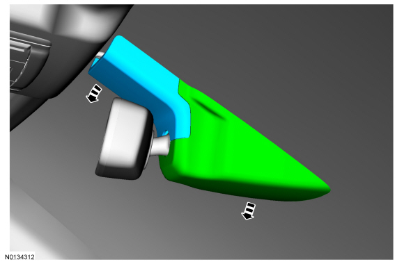
- NOTICE: To prevent damage to the mirror or base, rotate the
mirror base with hands only. Do not use tools.
NOTICE: To prevent damage to the mirror wiring, do not rotate the mirror head beyond 180 degrees.
Installation
- To install, reverse the removal procedure.
 Diagnosis and Testing
Rear View Mirrors - Exterior
DTC Chart(s)
Diagnostics in this manual assume a certain skill level and knowledge of
Ford-specific diagnostic practices. REFER to Section 100-00 for informatio ...
 Seating
...
Other materials:
Frame and Mounting
Uni-Body, Subframe and Mounting System
SPECIFICATIONS
Torque Specifications
DESCRIPTION AND OPERATION
Subframe and Mounting Systems
The front subframe is bolted to the body and:
aids in structural support.
provides the mounting surface for the steering gear, the front
suspension lower arms, en ...
General Procedures, Removal and Installation
GENERAL PROCEDURES
Tire Pressure Monitoring System (TPMS) Sensor Training - Integrated Keyhead
Transmitter (IKT)
Special Tool(s)
NOTE: If the vehicle has been stationary for more than 30 minutes, the
sensors will go into a "sleep mode" to conserve battery power. It will be
necessary to wake ...
Module Communications Network
DESCRIPTION AND OPERATION
Communications Network
Overview
Multiplexing is a method of sending 2 or more signals simultaneously on the
same network circuits. Multiplexing is used to allow 2 or more electronic
modules (nodes) to communicate simultaneously over a twisted-wire pair [data (+)
and data ...
