DESCRIPTION AND OPERATION
Communications Network
Overview
Multiplexing is a method of sending 2 or more signals simultaneously on the same network circuits. Multiplexing is used to allow 2 or more electronic modules (nodes) to communicate simultaneously over a twisted-wire pair [data (+) and data (-)] network. The information or messages that can be communicated on these wires consists of commands, status or data. The advantage of using multiplexing is to reduce the weight of the vehicle by reducing the number of redundant components and electrical wiring.
The vehicle has 3 module communication networks which are connected to the Data Link Connector (DLC), located under the instrument panel:
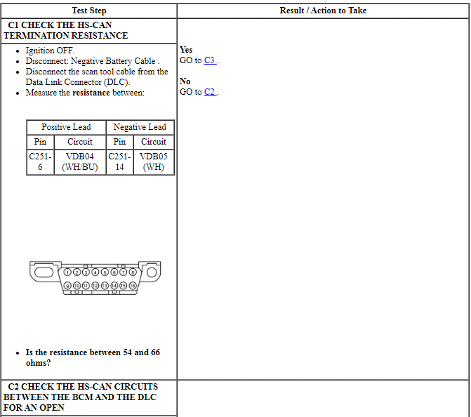
- High Speed Controller Area Network (HS-CAN)
- Medium Speed Controller Area Network (MS-CAN)
- Infotainment Controller Area Network (I-CAN)
System Operation
System Diagram
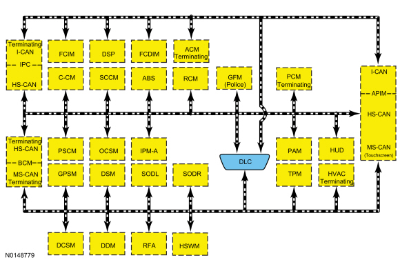
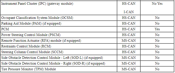
Module Network Chart
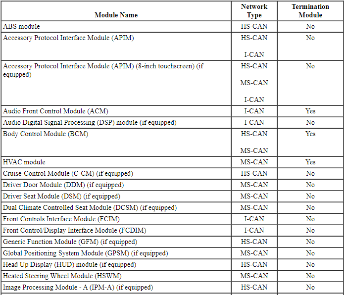
Network Termination
The Controller Area Network (CAN) uses network termination resistors to improve communication reliability. Termination modules are located at both ends of the network. As network messages are broadcast in the form of voltage signals, the network voltage signals are stabilized by the termination resistors.
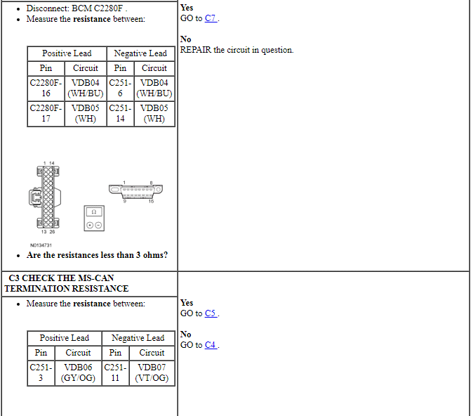
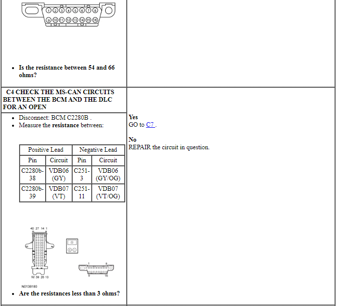
Each termination module has an internal 120 ohm resistor that bridges across the positive and negative bus connection. With two 120 ohm resistors located in a parallel circuit configuration, the total network impedance, or total resistance, is 60 ohms.
Network termination improves bus message reliability by:
- stabilizing bus voltage.
- eliminating electrical interference.
Gateway Module
The Body Control Module (BCM) and Instrument Panel Cluster (IPC) are the gateway modules. The BCM translates messages on the HS-CAN to the MS-CAN and vice versa. The IPC translates messages on the HS-CAN to the I-CAN and vice versa. This allows a message to be distributed through all three networks. The BCM and IPC are the only modules on this vehicle that have this ability.
High Speed Controller Area Network (HS-CAN)
The HS-CAN operates at a maximum data transfer speed of 500 Kbps and is designed for real time powertrain information transfer and control.
Modules on the HS-CAN communicate using bussed messages. The HS-CAN uses an unshielded twisted pair cable, data bus (+) and data bus (-) circuits. In addition to scan tool communication, the HS-CAN allows sharing of information between all modules on the network.
Medium Speed Controller Area Network (MS-CAN)
The MS-CAN operates at a maximum data transfer speed of 125 Kbps and is designed for general information transfer.
Modules on the MS-CAN communicate using bussed messages. The MS-CAN uses an unshielded twisted pair cable, data bus (+) and data bus (-) circuits. In addition to scan tool communication, the MS-CAN allows sharing of information between all modules on the network.
Infotainment Controller Area Network (I-CAN)
The I-CAN operates at a maximum data transfer speed of 500 Kbps and is designed for real time audio and multimedia information transfer and control.
Modules on the I-CAN communicate using bussed messages. I-CAN uses an unshielded twisted pair cable, data bus (+) and data bus (-) circuits. The I-CAN allows sharing of information between all modules on the network.
The I-CAN is connected to the DLC, but the I-CAN modules communicate with the scan tool over the HS-CAN. The IPC is used as a gateway module for the messages to transfer between the scan tool and the modules on the I-CAN.
Controller Area Network (CAN) Fault Tolerance
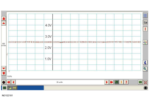
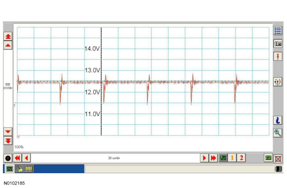
NOTE: The oscilloscope traces below are from the Integrated Diagnostic System (IDS) oscilloscope taken using the IDS pre-configured CAN settings. The traces are for both data (+) and data (-) taken simultaneously (2-channel) at a sample rate of 1 mega-sample per second (1MS/s) or greater.
Traces below are viewed at 500mV per division (vertical axis) and 20 microseconds (20μs) per division (horizontal axis). Readings taken with a different oscilloscope vary from those shown. Compare any suspect readings to a known good vehicle.
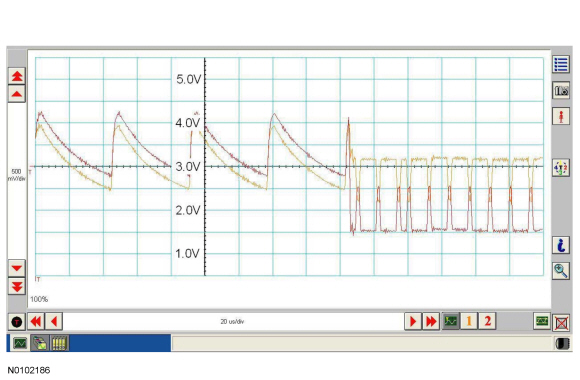
Normal CAN Operation
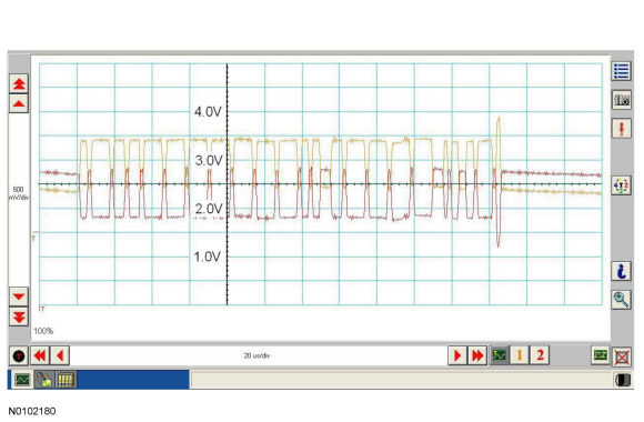
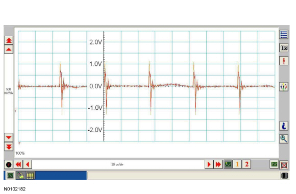
The data (+) and data (-) circuits are each regulated to approximately 2.5 volts during neutral or rested network traffic. As messages are sent on the data (+) circuit, voltage is increased by approximately 1.0 volt. Inversely, the data (-) circuit is reduced by approximately 1.0 volt when a message is sent.
Successful communication of a message can usually be identified by the slight spike at the end of a message transmission. Any signals that are significantly different than the normal CAN waveform may cause network DTCs (U-codes) to set or may cause a complete network outage.
CAN Circuits Shorted Together
In the event that the data (+) and data (-) circuits become shorted together, the signal stays at base voltage (2.5V) continuously and all communication capabilities are lost.
CAN (+) Circuit Shorted To Ground
In the event that the data (+) circuit becomes shorted to ground, both the data (+) and data (-) circuits are pulled low (0V) and all communication capabilities are lost.
CAN (-) Circuit Shorted To Ground
In the event that the data (-) circuit becomes shorted to ground, the data (-) circuit is pulled low (0V) and the data (+) circuit reaches near-normal peak voltage (3.0V) during communication but falls to 0V instead of normal base voltage (2.5V). Communication may continue but at a degraded level.
CAN (+) Circuit Shorted To Battery Voltage
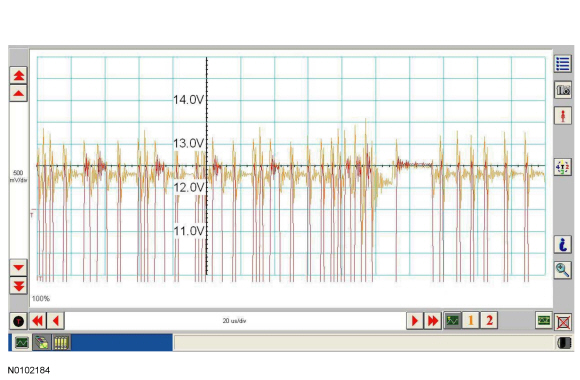
In the event that the data (+) circuit becomes shorted to battery voltage, the data (+) circuit is pulled high (12V) and the data (-) circuit falls to abnormally high voltage (above 5V) during communication and reaches battery voltage (12V) for peak voltage. Communication may continue but at a degraded level.
CAN (-) Circuit Shorted To Battery Voltage
In the event that the data (-) circuit becomes shorted to battery voltage, both the data (+) and data (-) circuits are pulled high (12V) and all communication capabilities are lost.
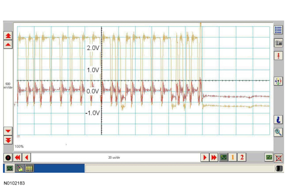
CAN Circuit Signal Corruption
Rhythmic oscillations, inductive spikes or random interference can disrupt the network communications. The corruption signal source may be outside electrical interference such as motors or solenoids or internal interference generated from a module on the network. In some cases, an open in either the data (+) or data (-) circuit to a network module may cause the module to emit interference on the one circuit which is still connected. The trace shown is an example of a "sawtooth" pattern transmitted from a module with one open network circuit.
Other corruptions may be present when a module is intermittently powered up and down. The module on power up may initiate communication out of sync with other modules on the network causing momentary communication outages.
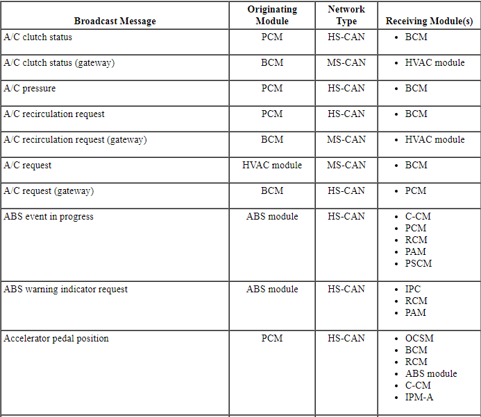
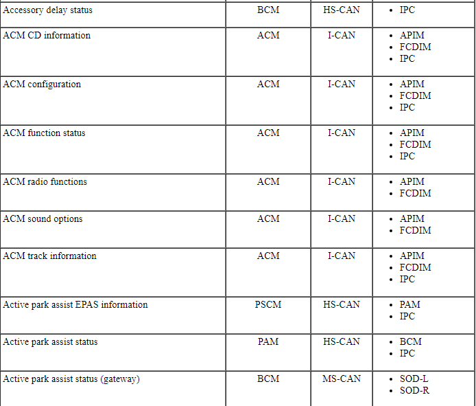
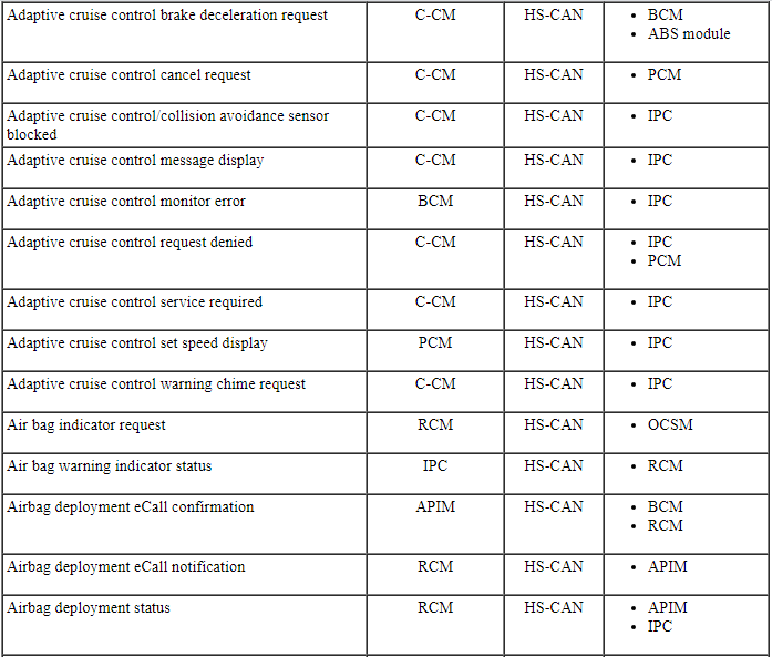
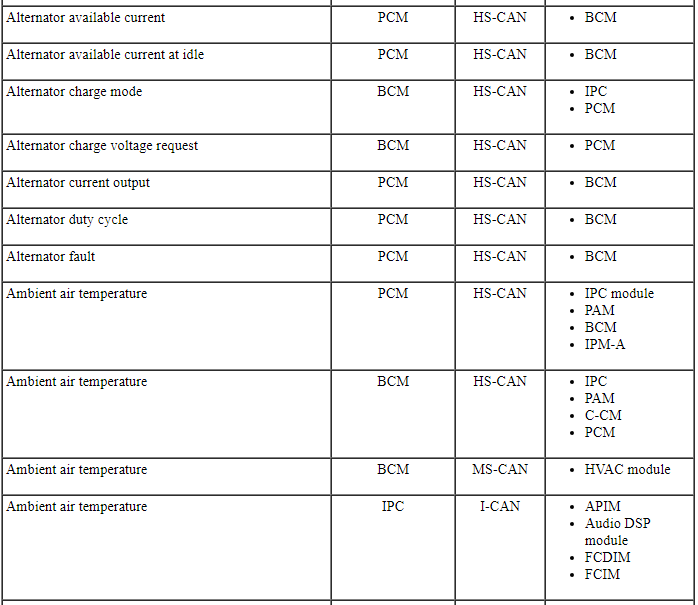
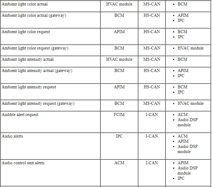
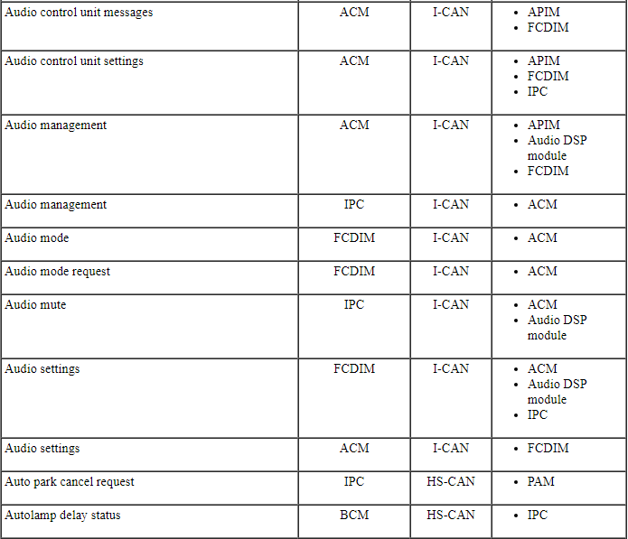
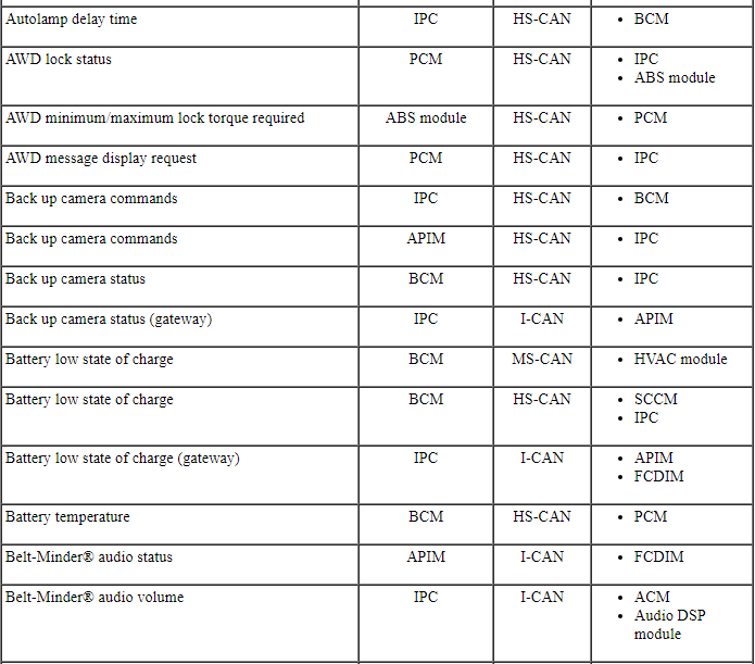
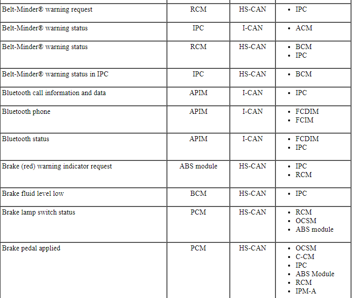
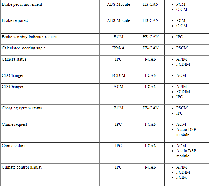
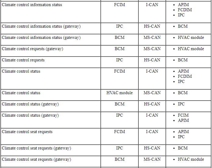
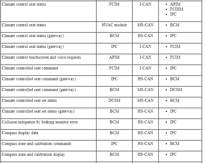
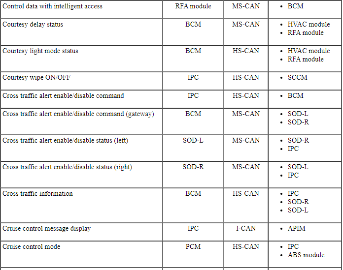
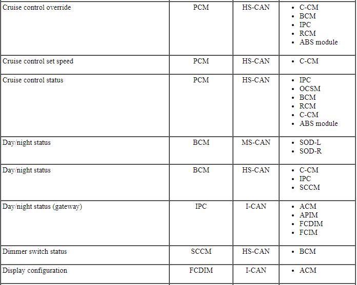
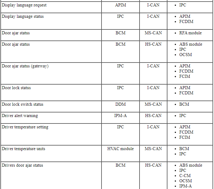
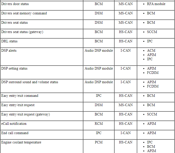
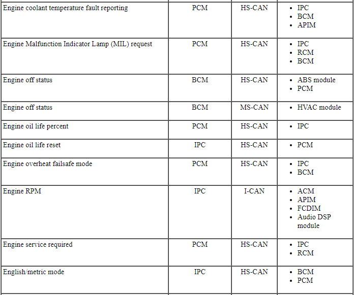
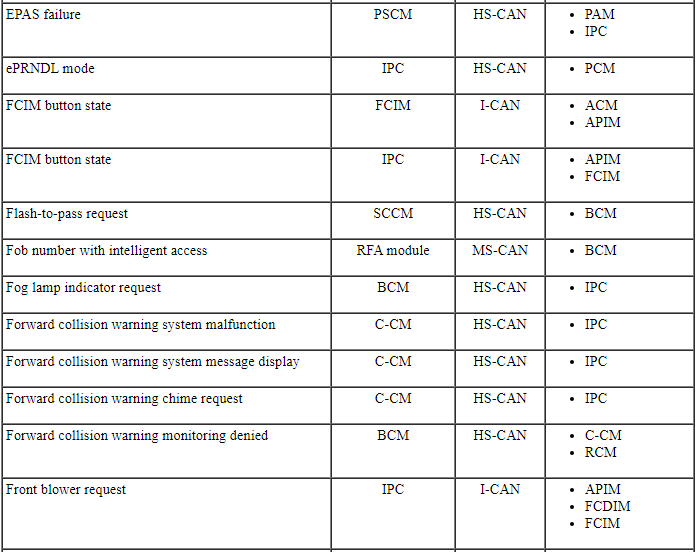
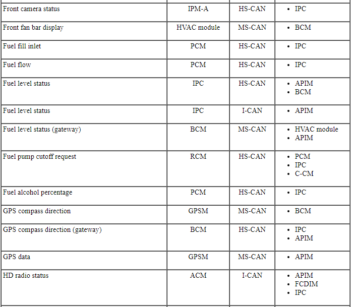
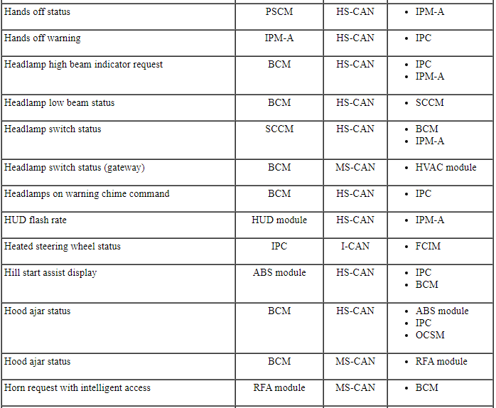
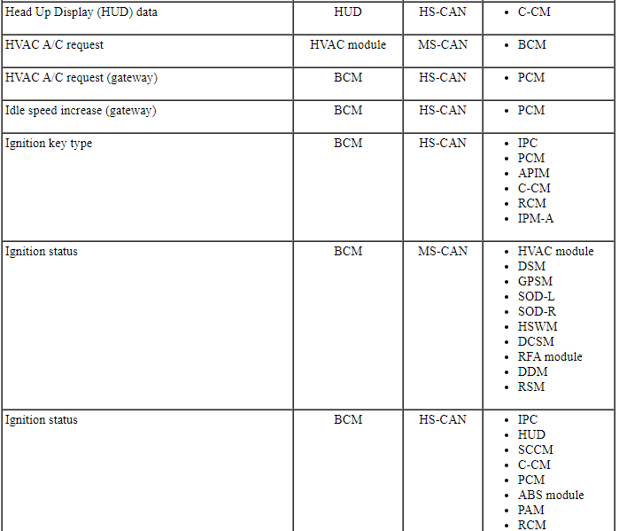
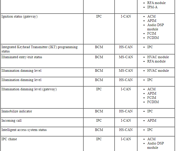
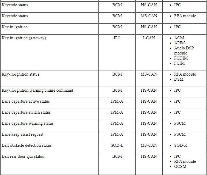
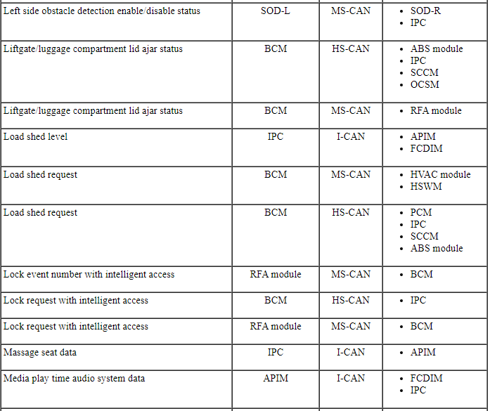
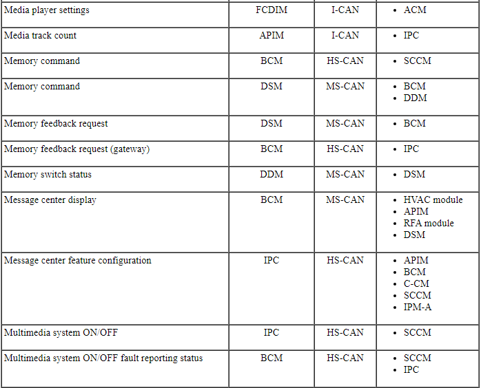
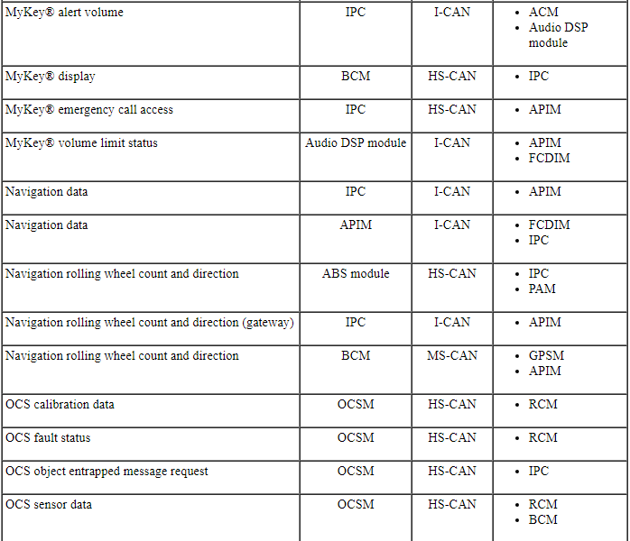
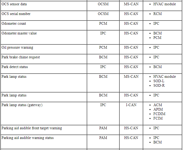
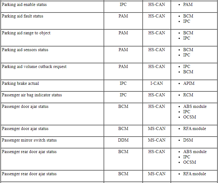
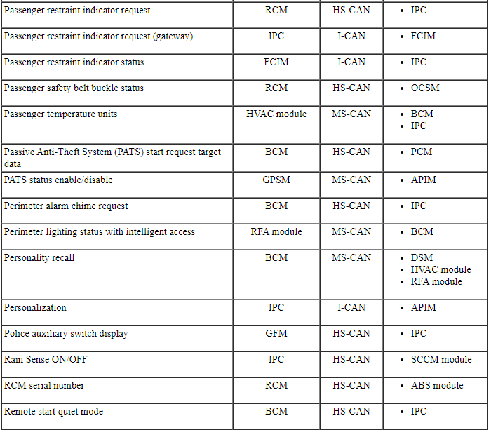
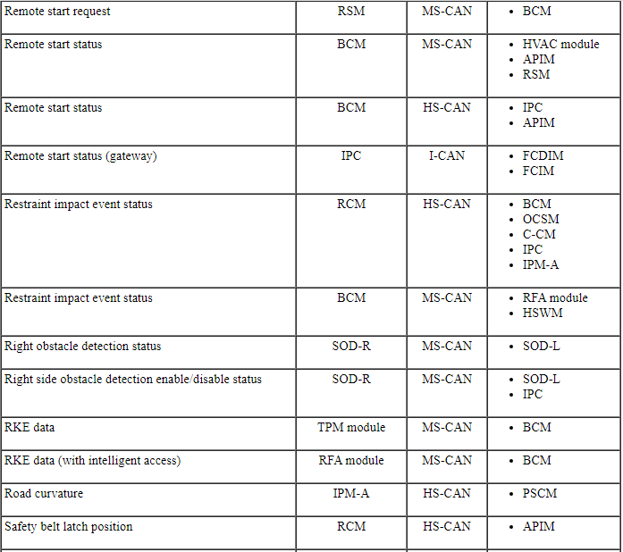
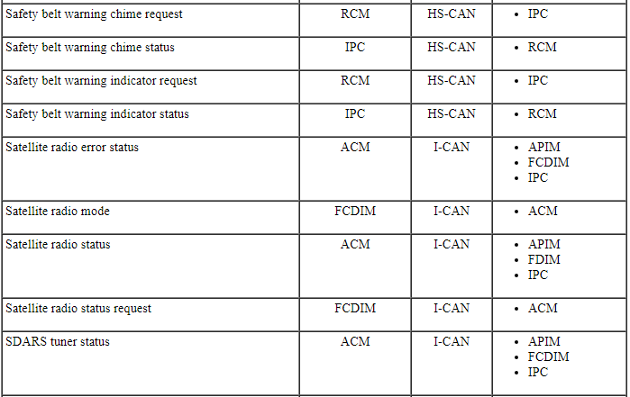
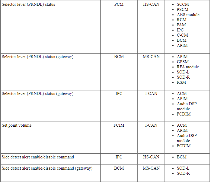
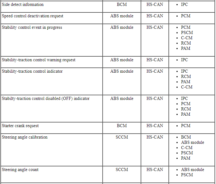
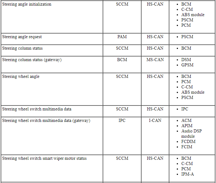
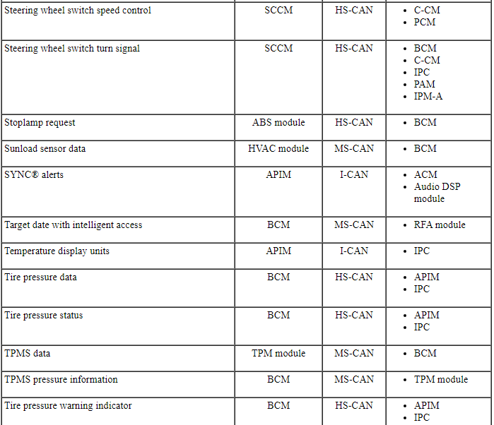
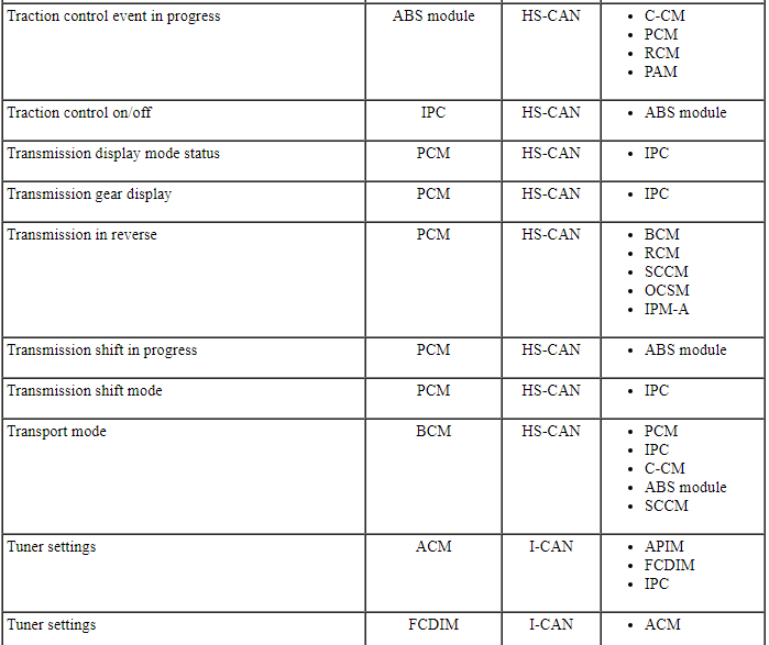
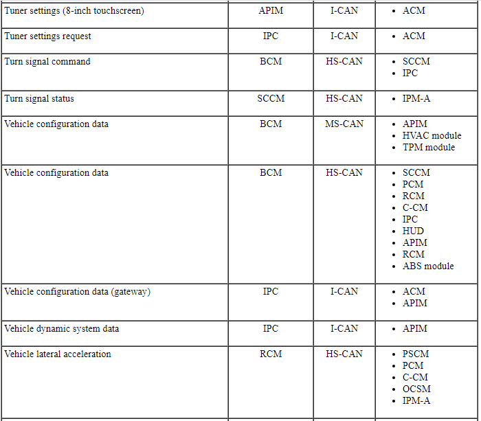
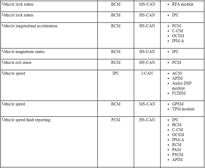
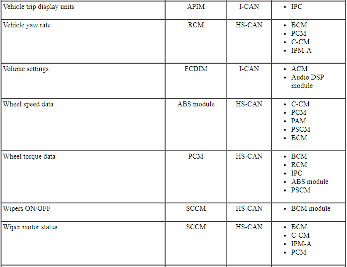
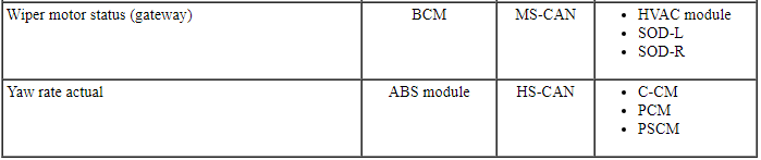
Controller Area Network (CAN) Multiplex Messages
Modules on the CAN utilize simultaneous communication of 2 or more messages on the same network circuits. The following chart summarizes the messages sent and received on the network.
Communication Message Chart
NOTE: This chart describes the specific HS-CAN, MS-CAN and I-CAN messages broadcast by each module, and the module(s) that receive the message.
DIAGNOSIS AND TESTING
Communications Network
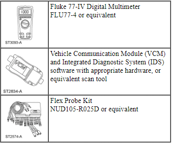
Special Tool(s)
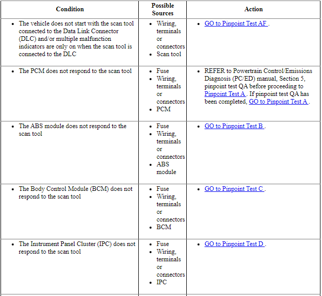
Symptom Chart
Diagnostics in this manual assume a certain skill level and knowledge of Ford-specific diagnostic practices. Refer to Diagnostic Methods in Section 100-00 for information about these practices.
Pinpoint Tests
Pinpoint Test A: The PCM Does Not Respond To The Scan Tool
Diagnostic Overview
Diagnostics in this manual assume a certain skill level and knowledge of Ford-specific diagnostic practices. Refer to Diagnostic Methods in Section 100-00 for information about these practices.
Refer to Wiring Diagrams Cell 14, Module Communications Network for schematic and connector information.
Refer to Wiring Diagrams Cell 23, Electronic Engine Controls - 2.0L GTDI for schematic and connector information.
Refer to Wiring Diagrams Cell 24, Electronic Engine Controls - 3.5L/3.7L Ti-VCT for schematic and connector information.
Refer to Wiring Diagrams Cell 25, Electronic Engine Controls - 3.5L GTDI for schematic and connector information.
Normal Operation and Fault Conditions
The PCM communicates with the scan tool through the High Speed Controller Area Network (HS-CAN). An IDS session cannot be established if the PCM communication fails when attempting to identify the vehicle.
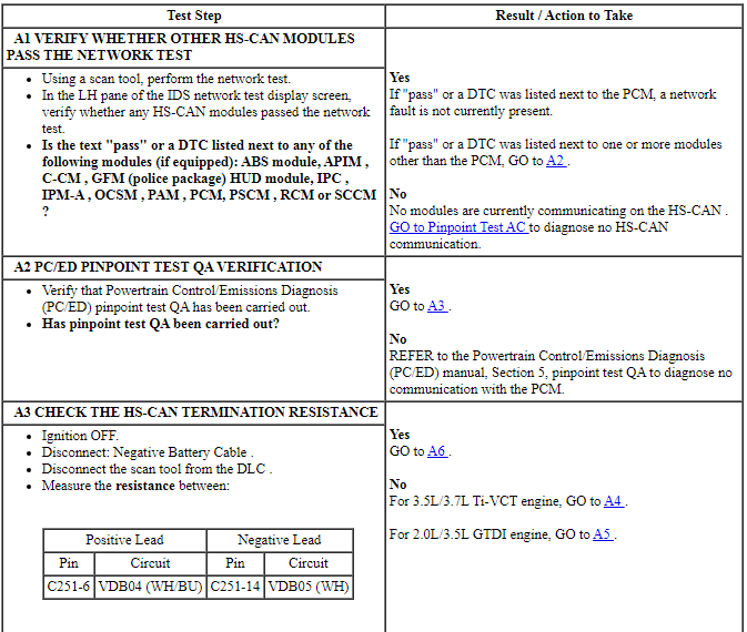
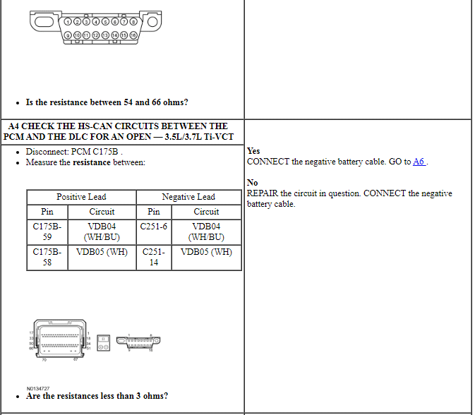
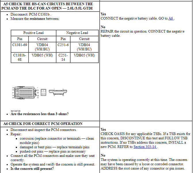
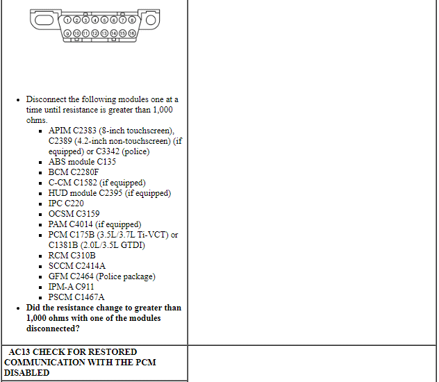
PINPOINT TEST A: THE PCM DOES NOT RESPOND TO THE SCAN TOOL
NOTE: Failure to disconnect the battery when instructed will result in false resistance readings. Refer to Section 414-01.
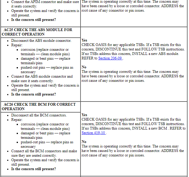
Pinpoint Test B: The ABS Module Does Not Respond To The Scan Tool
Diagnostic Overview
Diagnostics in this manual assume a certain skill level and knowledge of Ford-specific diagnostic practices. Refer to Diagnostic Methods in Section 100-00 for information about these practices.
Refer to Wiring Diagrams Cell 14, Module Communications Network for schematic and connector information.
Refer to Wiring Diagrams Cell 42, Vehicle Dynamic Systems for schematic and connector information.
Normal Operation and Fault Conditions
The ABS module communicates with the scan tool through the High Speed Controller Area Network (HS-CAN).
Visual Inspection and Diagnostic Pre-checks
Verify BJB fuses 5 (50A), 43 (20A) and 92 (10A) are OK.
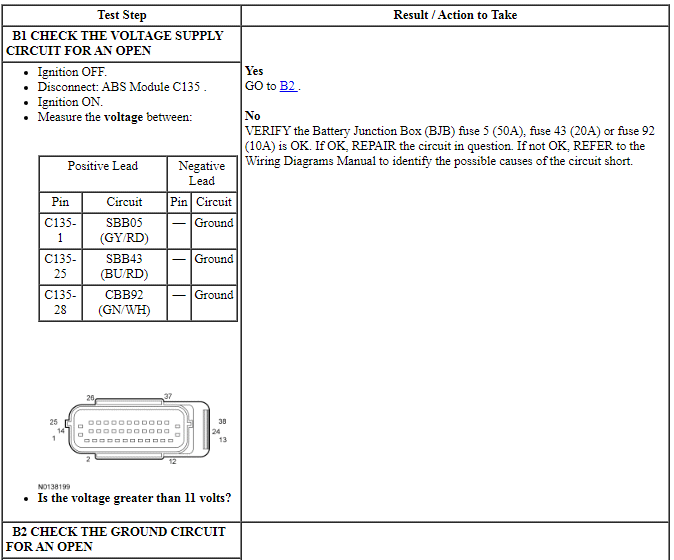
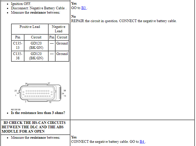
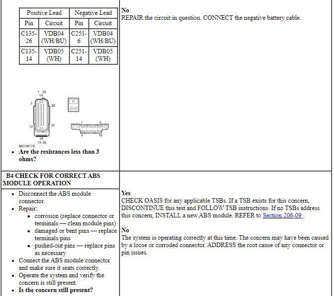
PINPOINT TEST B: THE ABS MODULE DOES NOT RESPOND TO THE SCAN TOOL
NOTE: Failure to disconnect the battery when instructed will result in false resistance readings. Refer to Section 414-01.
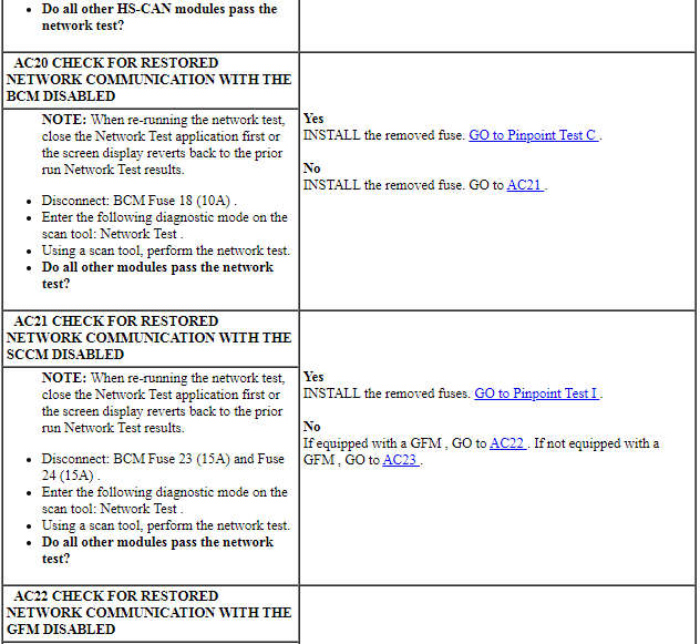
Pinpoint Test C: The Body Control Module (BCM) Does Not Respond To The Scan Tool
Diagnostic Overview
Diagnostics in this manual assume a certain skill level and knowledge of Ford-specific diagnostic practices. Refer to Diagnostic Methods in Section 100-00 for information about these practices.
Refer to Wiring Diagrams Cell 10, Grounds for schematic and connector information.
Refer to Wiring Diagrams Cell 13, Power Distribution/BCM for schematic and connector information.
Refer to Wiring Diagrams Cell 14, Module Communications Network for schematic and connector information.
Normal Operation and Fault Conditions
The Body Control Module (BCM) communicates with the scan tool through the High Speed Controller Area Network (HS-CAN) and communicates with the other modules through the Medium Speed Controller Area Network (MS-CAN).
Visual Inspection and Diagnostic Pre-checks
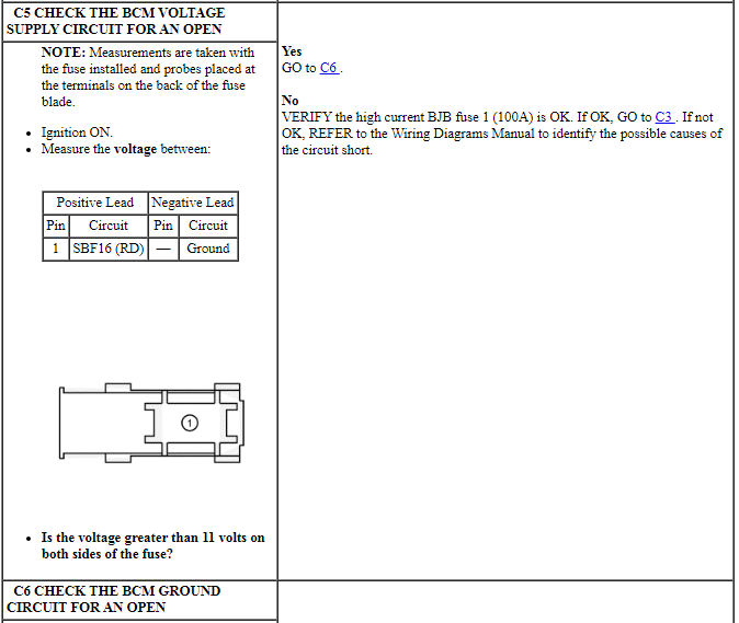
Verify high current BJB fuse 1 (100A) is OK.
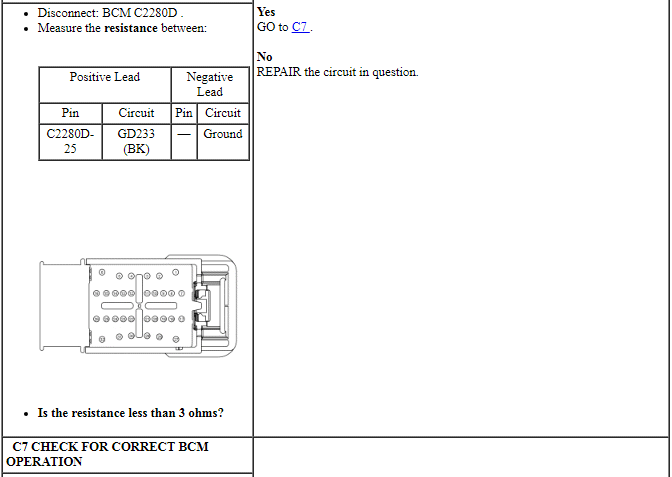
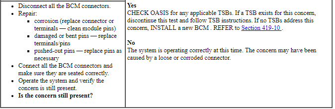
PINPOINT TEST C: THE BCM DOES NOT RESPOND TO THE SCAN TOOL
NOTE: Failure to disconnect the battery when instructed results in false resistance readings. Refer to Section 414-01.
Pinpoint Test D: The Instrument Panel Cluster (IPC) Does Not Respond To The Scan Tool
Diagnostic Overview
Diagnostics in this manual assume a certain skill level and knowledge of Ford-specific diagnostic practices. Refer to Diagnostic Methods in Section 100-00 for information about these practices.
Refer to Wiring Diagrams Cell 14, Module Communications Network for schematic and connector information.
Refer to Wiring Diagrams Cell 60, Instrument Cluster for schematic and connector information.
Normal Operation and Fault Conditions
The Instrument Panel Cluster (IPC) communicates with the scan tool and other network modules on the High Speed Controller Area Network (HS-CAN) and communicates with other network modules through the Infotainment Controller Area Network (I-CAN).
Visual Inspection and Diagnostic Pre-checks
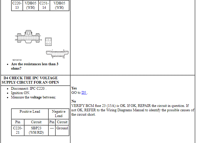
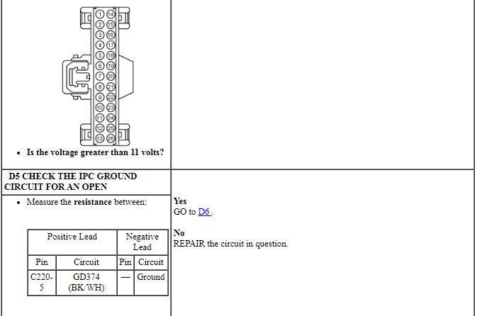
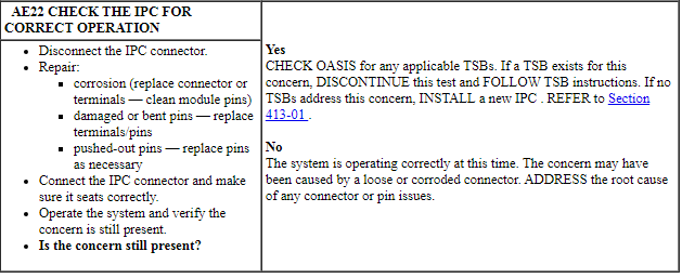
Verify BCM fuse 23 (15A) is OK.
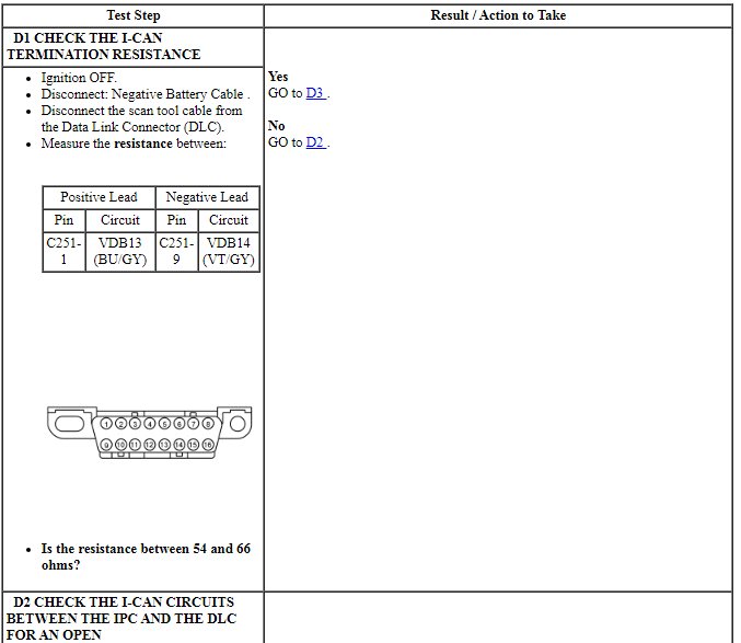
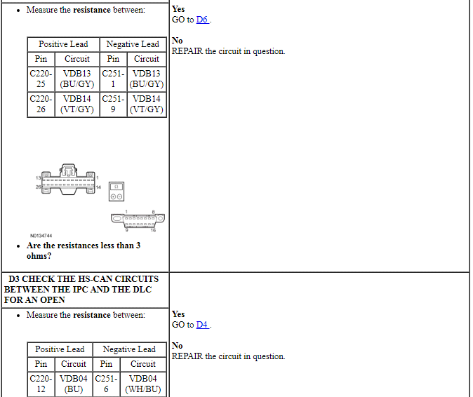
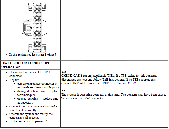
PINPOINT TEST D: THE IPC DOES NOT RESPOND TO THE SCAN TOOL
NOTE: Failure to disconnect the battery when instructed will result in false resistance readings. Refer to Section 414-01.
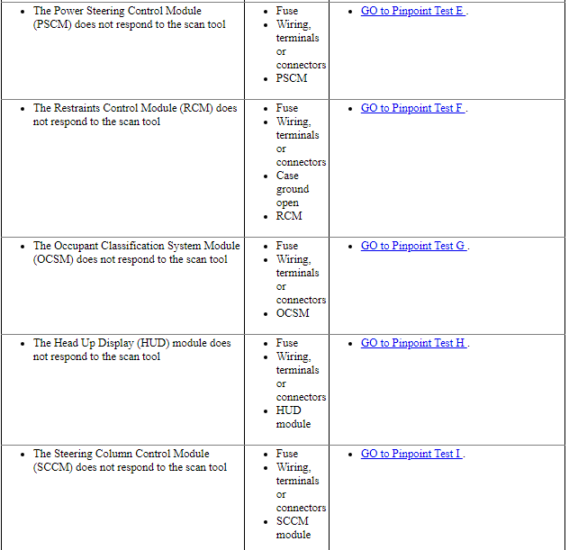
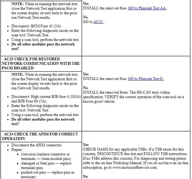
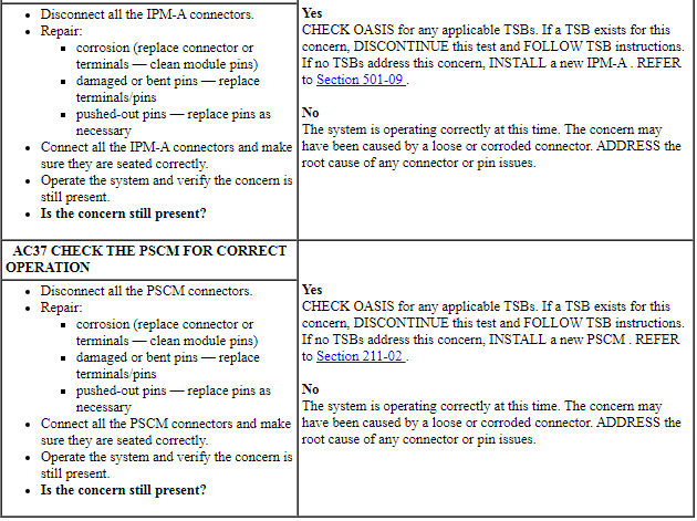
Pinpoint Test E: The Power Steering Control Module (PSCM) Does Not Respond To The Scan Tool
Diagnostic Overview
Diagnostics in this manual assume a certain skill level and knowledge of Ford-specific diagnostic practices. Refer to Diagnostic Methods in Section 100-00 for information about these practices.
Refer to Wiring Diagrams Cell 14, Module Communications Network for schematic and connector information.
Refer to Wiring Diagrams Cell 43, Power Steering Controls for schematic and connector information.
Normal Operation and Fault Conditions
The Power Steering Control Module (PSCM) communicates with the scan tool through the High Speed Controller Area Network (HS-CAN).
Visual Inspection and Diagnostic Pre-Checks
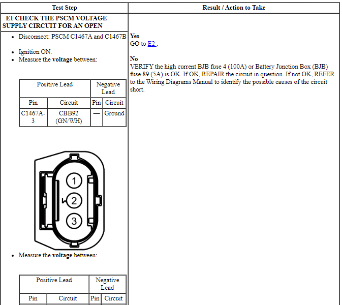
Verify high current BJB fuse 4 (100A) and BJB 89 (5A) is OK.
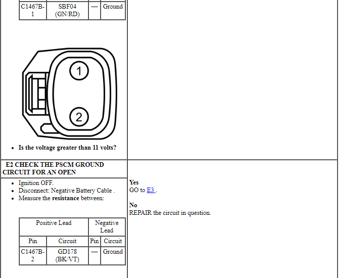
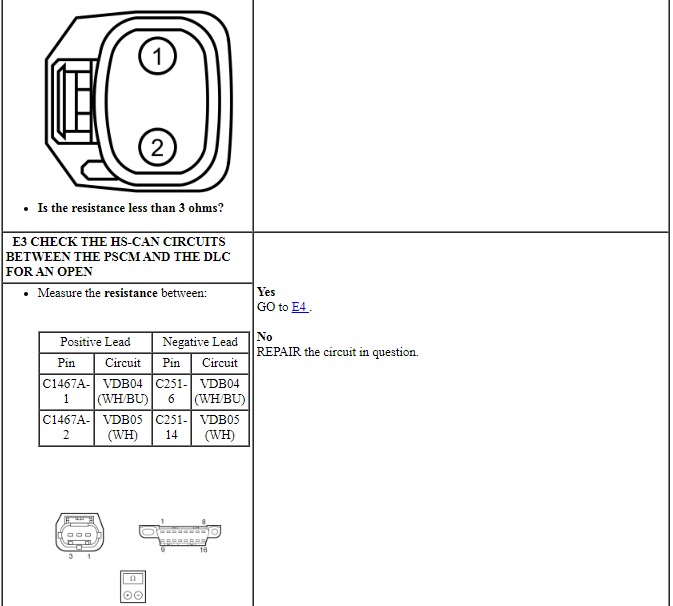
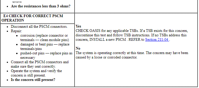
PINPOINT TEST E: THE PSCM DOES NOT RESPOND TO THE SCAN TOOL
NOTE: Failure to disconnect the battery when instructed will result in false resistance readings. Refer to Section 414-01.
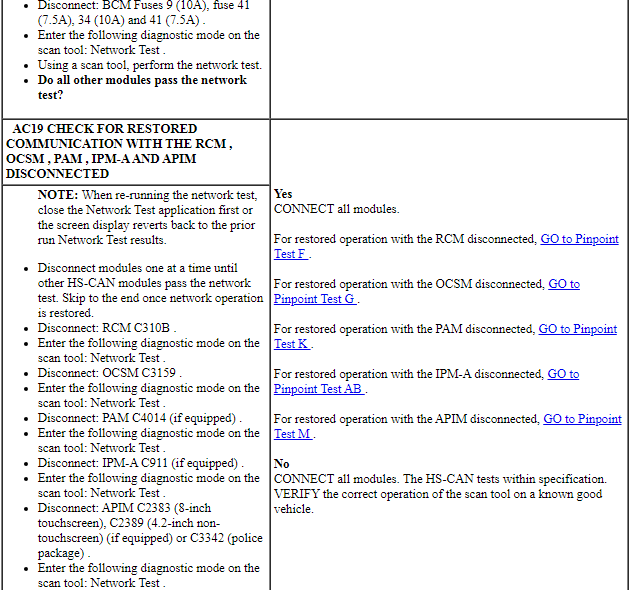
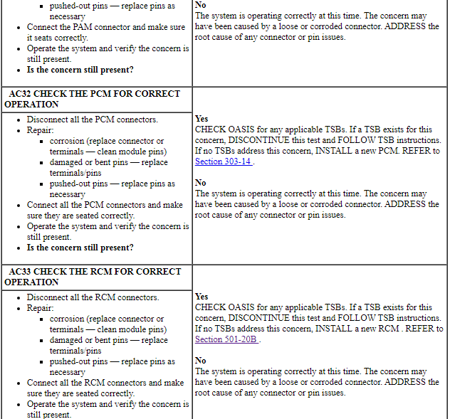
Pinpoint Test F: The Restraints Control Module (RCM) Does Not Respond To The Scan Tool
Diagnostic Overview
Diagnostics in this manual assume a certain skill level and knowledge of Ford-specific diagnostic practices. Refer to Diagnostic Methods in Section 100-00 for information about these practices.
Refer to Wiring Diagrams Cell 14, Module Communications Network for schematic and connector information.
Refer to Wiring Diagrams Cell 46, Supplemental Restraint System for schematic and connector information.
Normal Operation and Fault Conditions
The Restraints Control Module (RCM) communicates with the scan tool through the High Speed Controller Area Network (HS-CAN).
Visual Inspection and Diagnostic Pre-checks
Verify BCM fuse 41 (7.5A) is OK.
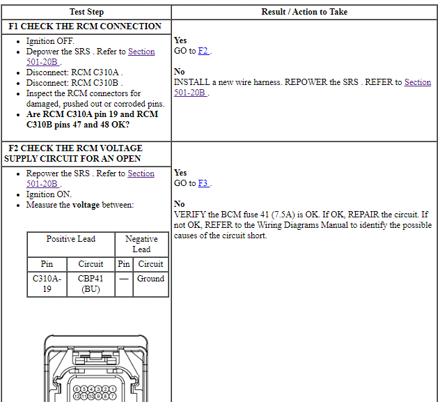
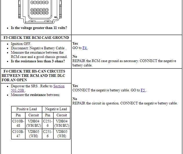
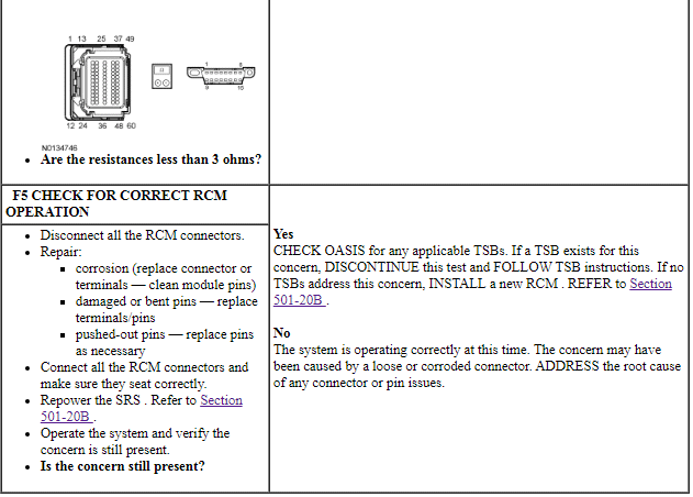
PINPOINT TEST F: THE RCM DOES NOT RESPOND TO THE SCAN TOOL
WARNING: Never probe the electrical connectors on airbag, Safety Canopy or side air curtain assemblies. Failure to follow this instruction may result in the accidental deployment of these assemblies, which increases the risk of serious personal injury or death.
WARNING: Never disassemble or tamper with seat belt deployable components, including pretensioners, load limiters and inflators. Never back probe deployable device electrical connectors. Tampering or back probing may cause an accidental deployment and result in personal injury or death.
NOTE: Failure to disconnect the battery when instructed will result in false resistance readings. Refer to Section 414-01.
NOTE: The Supplemental Restraint System (SRS) must be fully operational and free of faults before releasing the vehicle to the customer.
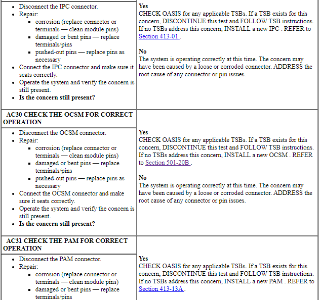
Pinpoint Test G: The Occupant Classification System Module (OCSM) Does Not Communicate With the Scan Tool
Diagnostic Overview
Diagnostics in this manual assume a certain skill level and knowledge of Ford-specific diagnostic practices. Refer to Diagnostic Methods in Section 100-00 for information about these practices.
Refer to Wiring Diagrams Cell 14, Module Communications Network for schematic and connector information.
Refer to Wiring Diagrams Cell 46, Supplemental Restraint System for schematic and connector information.
Normal Operation and Fault Conditions
The Occupant Classification System Module (OCSM) communicates with the scan tool through the High Speed Controller Area Network (HS-CAN).
Visual Inspection and Diagnostic Pre-checks
Verify BCM fuse 41 (7.5A) is OK.
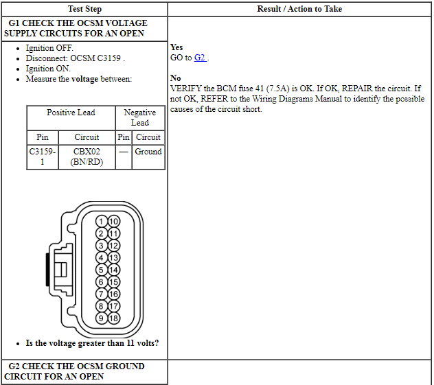
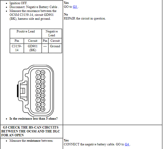
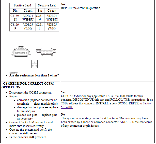
PINPOINT TEST G: THE OCSM DOES NOT COMMUNICATE WITH THE SCAN TOOL
NOTE: Failure to disconnect the battery when instructed will result in false resistance readings. Refer to Section 414-01.
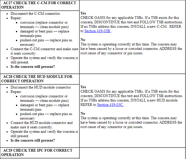
Pinpoint Test H: The Head Up Display (HUD) Module Does Not Respond To The Scan Tool
Diagnostic Overview
Diagnostics in this manual assume a certain skill level and knowledge of Ford-specific diagnostic practices. Refer to Diagnostic Methods in Section 100-00 for information about these practices.
Refer to Wiring Diagrams Cell 14, Module Communications Network for schematic and connector information.
Refer to Wiring Diagrams Cell 136, Vehicle Emergency Messaging System for schematic and connector information.
Normal Operation and Fault Conditions
The Head Up Display (HUD) module communicates with the scan tool through the High Speed Controller Area Network (HS-CAN).
Visual Inspection and Diagnostic Pre-checks
Verify BCM fuse 11 (10A) or fuse 35 (5A) is OK.
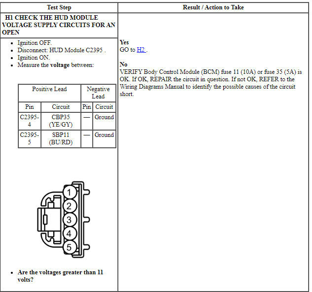
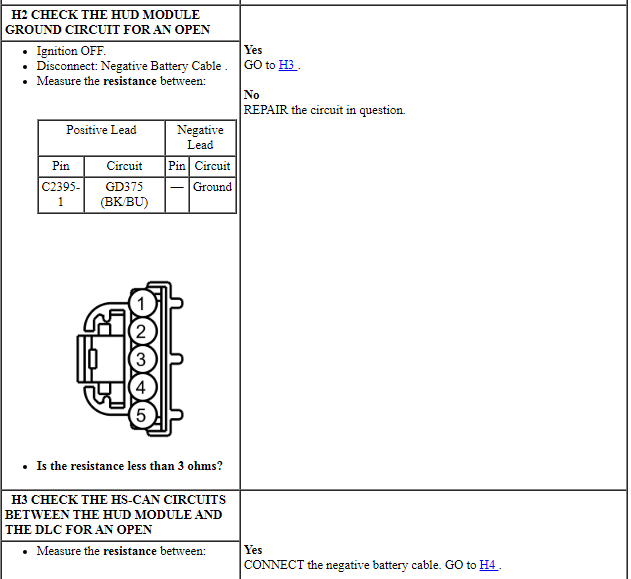
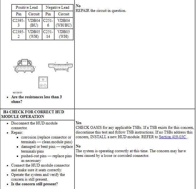
PINPOINT TEST H: THE HUD MODULE DOES NOT RESPOND TO THE SCAN TOOL
NOTE: Failure to disconnect the battery when instructed will result in false resistance readings. Refer to Section 414-01.
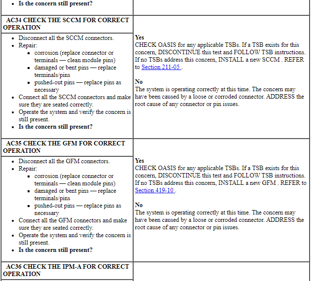
Pinpoint Test I: The Steering Column Control Module (SCCM) Does Not Respond To The Scan Tool
Diagnostic Overview
Diagnostics in this manual assume a certain skill level and knowledge of Ford-specific diagnostic practices. Refer to Diagnostic Methods in Section 100-00 for information about these practices.
Refer to Wiring Diagrams Cell 14, Module Communications Network for schematic and connector information.
Refer to Wiring Diagrams Cell 90, Turn Signal/Stop/Hazard Lamps for schematic and connector information.
Normal Operation and Fault Conditions
The Steering Column Control Module (SCCM) communicates with the scan tool through the High Speed Controller Area Network (HS-CAN).
Visual Inspection and Diagnostic Pre-checks
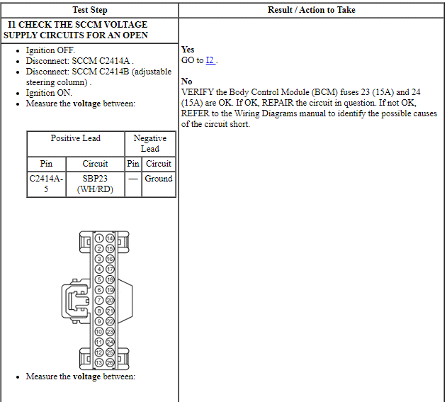
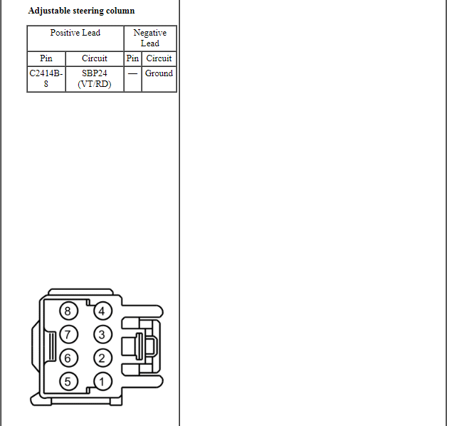
Verify BCM fuse 23 (15A) or fuse 24 (15A) is OK.
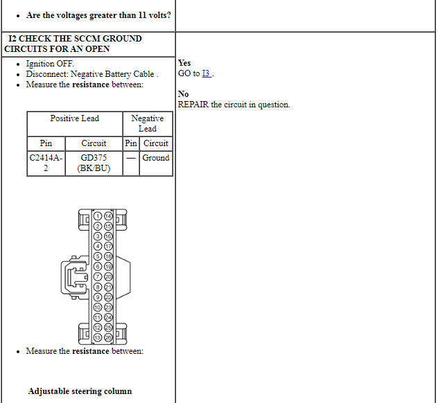
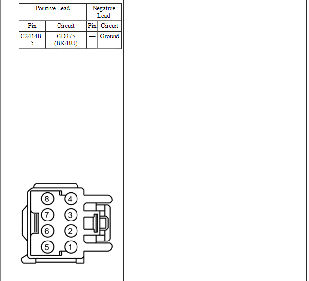
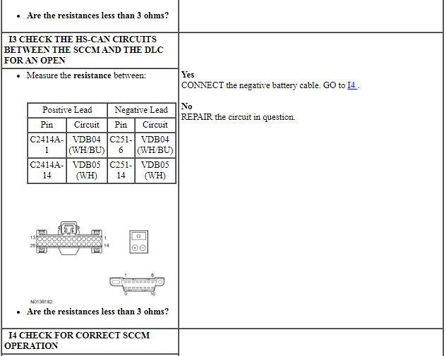
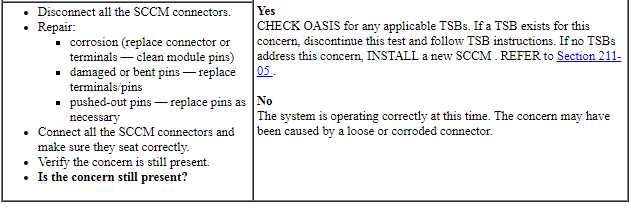
PINPOINT TEST I: THE SCCM DOES NOT RESPOND TO THE SCAN TOOL
NOTE: Failure to disconnect the battery when instructed results in false resistance readings. Refer to Section 414-01.
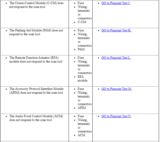
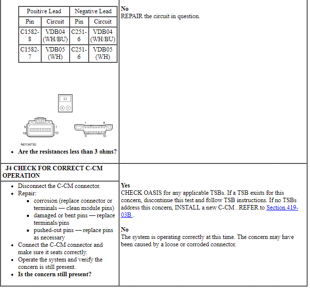
Pinpoint Test J: The Cruise-Control Module (C-CM) Does Not Communicate With the Scan Tool
Diagnostic Overview
Diagnostics in this manual assume a certain skill level and knowledge of Ford-specific diagnostic practices. Refer to Diagnostic Methods in Section 100-00 for information about these practices.
Refer to Wiring Diagrams Cell 14, Module Communications Network for schematic and connector information.
Refer to Wiring Diagrams Cell 31, Cruise Control for schematic and connector information.
Normal Operation and Fault Conditions
The Cruise-Control Module (C-CM) communicates with the scan tool through the HS-CAN.
Visual Inspection and Diagnostic Pre-checks
Verify BJB fuse 79 (5A) or fuse 91 (10A) is OK.
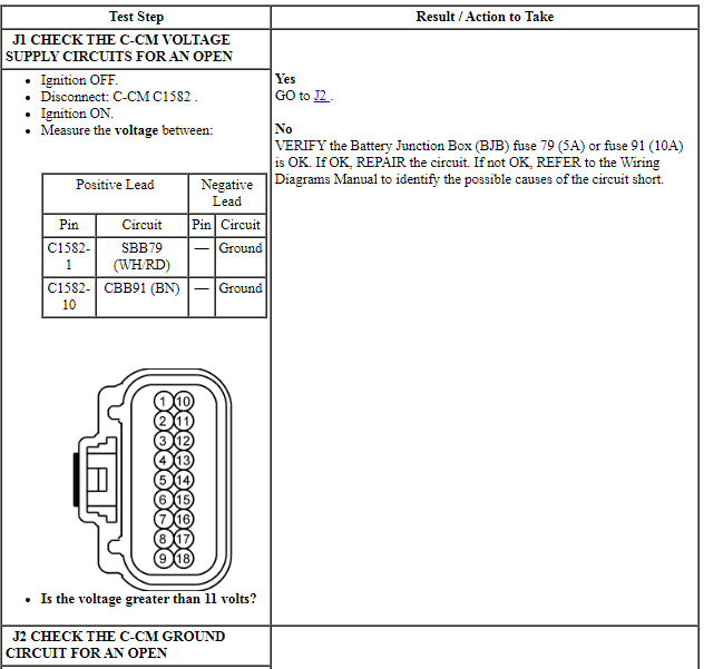
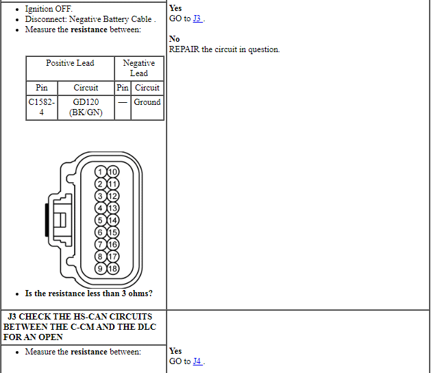
PINPOINT TEST J: THE C-CM DOES NOT COMMUNICATE WITH THE SCAN TOOL
NOTE: Failure to disconnect the battery when instructed will result in false resistance readings. Refer to Section 414-01.
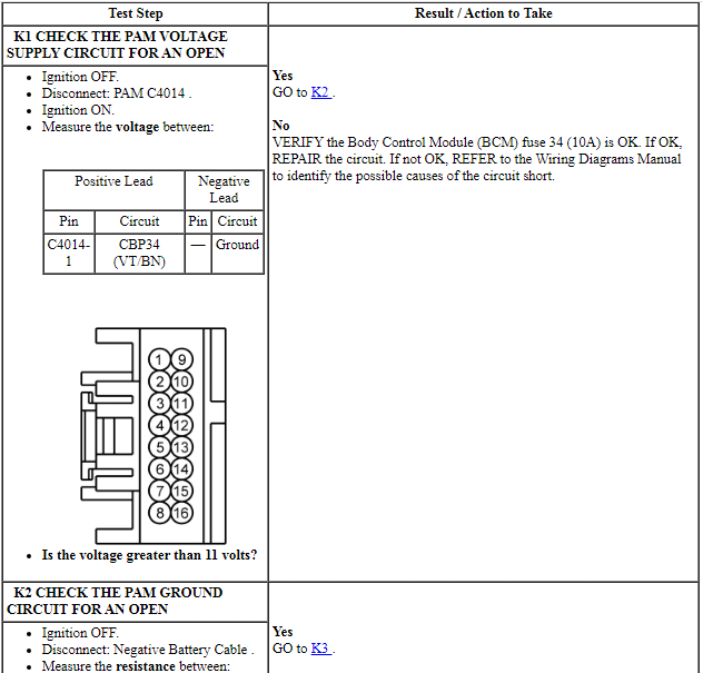
Pinpoint Test K: The Parking Aid Module (PAM) Does Not Respond To The Scan Tool
Diagnostic Overview
Diagnostics in this manual assume a certain skill level and knowledge of Ford-specific diagnostic practices. Refer to Diagnostic Methods in Section 100-00 for information about these practices.
Refer to Wiring Diagrams Cell 14, Module Communications Network for schematic and connector information.
Refer to Wiring Diagrams Cell 131, Parking Aid for schematic and connector information.
Normal Operation and Fault Conditions
The Parking Aid Module (PAM) communicates with the scan tool through the High Speed Controller Area Network (HS-CAN).
Visual Inspection and Diagnostic Pre-checks
Verify BCM fuse 34 (10A) is OK.
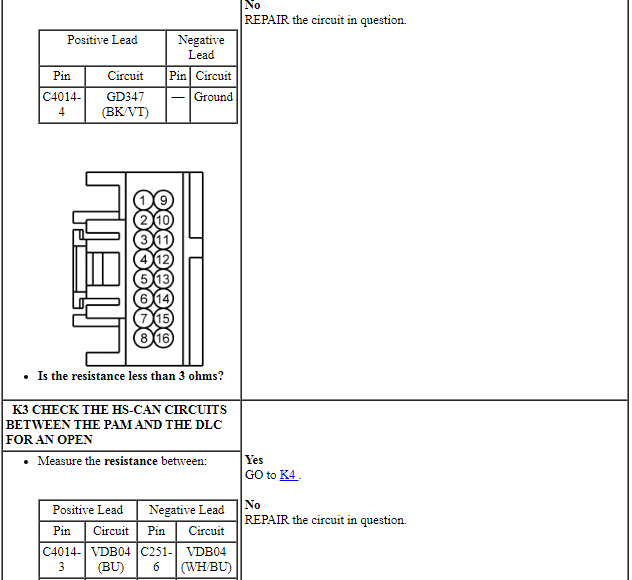
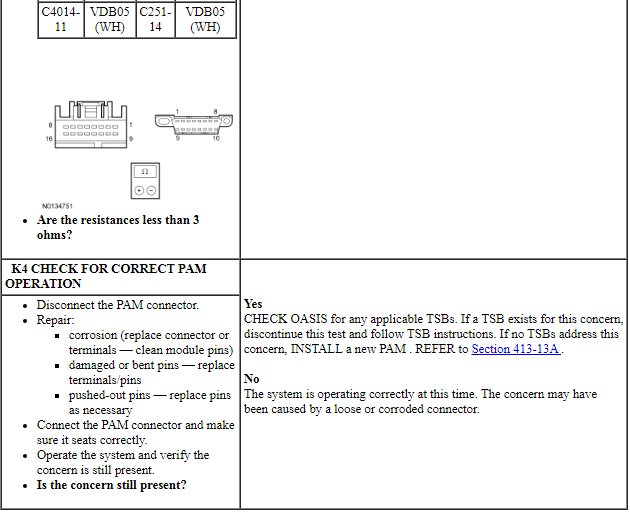
PINPOINT TEST K: THE PAM DOES NOT RESPOND TO THE SCAN TOOL
NOTE: Failure to disconnect the battery when instructed will result in false resistance readings. Refer to Section 414-01.
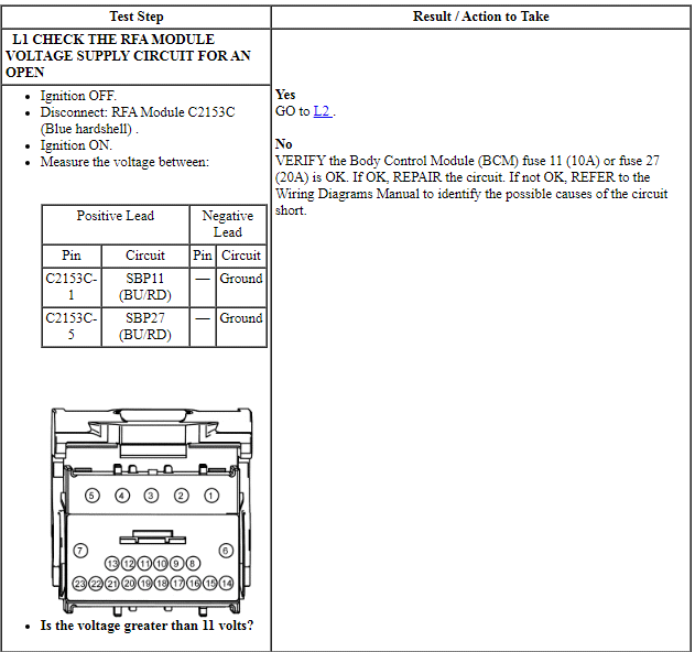
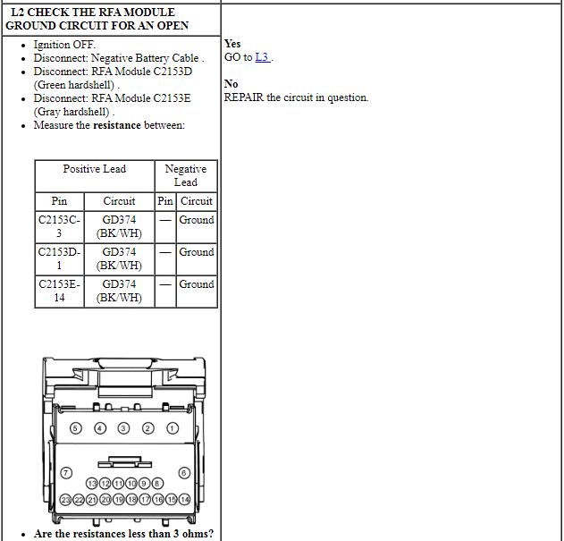
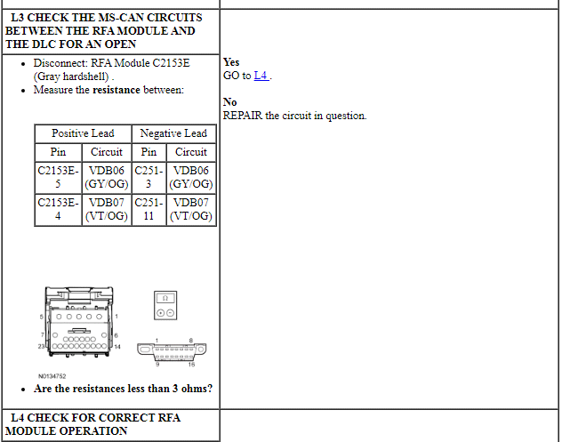
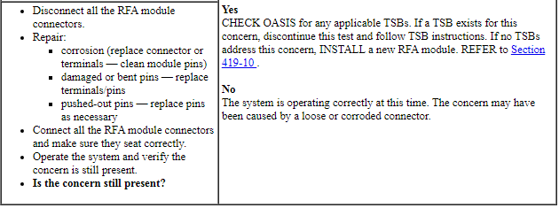
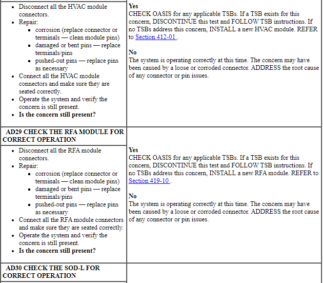
Pinpoint Test L: The Remote Function Actuator (RFA) Module Does Not Respond To The Scan Tool
Diagnostic Overview
Diagnostics in this manual assume a certain skill level and knowledge of Ford-specific diagnostic practices. Refer to Diagnostic Methods in Section 100-00 for information about these practices.
Refer to Wiring Diagrams Cell 14, Module Communications Network for schematic and connector information.
Refer to Wiring Diagrams Cell 110, Power Door Locks for schematic and connector information.
Normal Operation and Fault Conditions
The Remote Function Actuator (RFA) module communicates with the scan tool through the Medium Speed Controller Area Network (MS-CAN).
Visual Inspection and Diagnostic Pre-checks
Verify BCM fuse 11 (10A) or fuse 27 (20A)
PINPOINT TEST L: THE RFA MODULE DOES NOT RESPOND TO THE SCAN TOOL
NOTE: Failure to disconnect the battery when instructed will result in false resistance readings. Refer to Section 414-01.
Pinpoint Test M: The Accessory Protocol Interface Module (APIM) Does Not Respond To The Scan Tool
Diagnostic Overview
Diagnostics in this manual assume a certain skill level and knowledge of Ford-specific diagnostic practices. Refer to Diagnostic Methods in Section 100-00 for information about these practices.
Refer to Wiring Diagrams Cell 14, Module Communications Network for schematic and connector information.
Refer to Wiring Diagrams Cell 130, Audio System/Navigation for schematic and connector information.
Normal Operation and Fault Conditions
TheAccessory Protocol Interface Module (APIM) communicates with the scan tool and other network modules on the High Speed Controller Area Network (HS-CAN). The APIM also communicates with other network modules on the Medium Speed Controller Area Network (MS-CAN) and the Infotainment Controller Area Network (I-CAN) with an 8-inch touchscreen.
Visual Inspection and Diagnostic Pre-checks
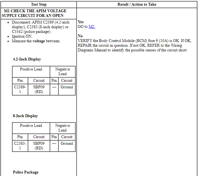
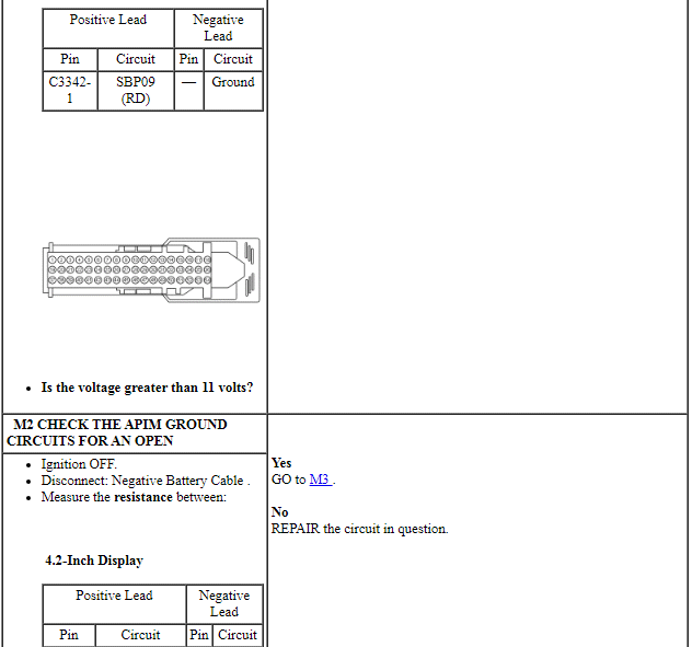
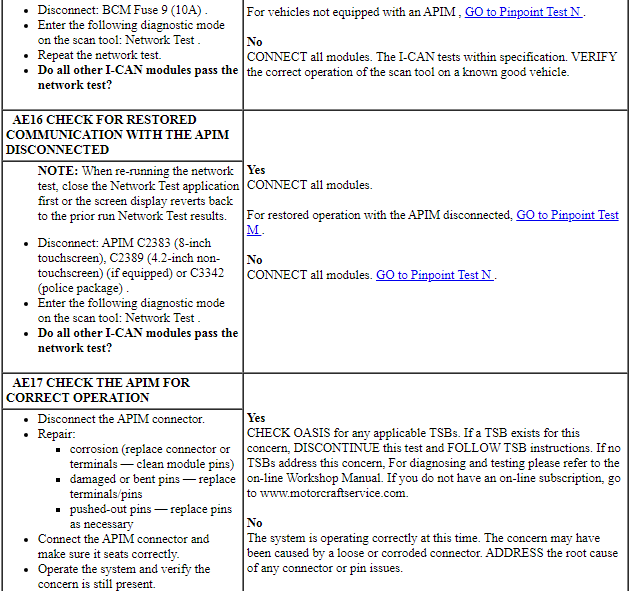
Verify BCM fuse 9 (10A) is OK.
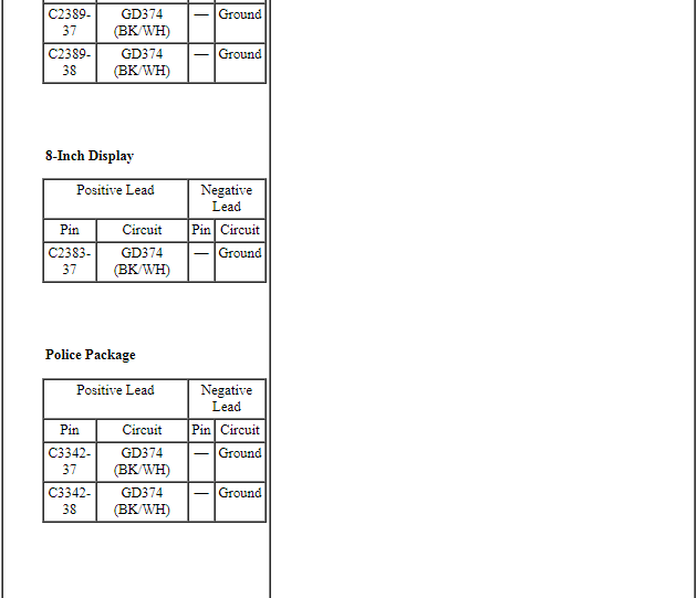
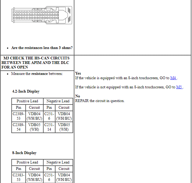
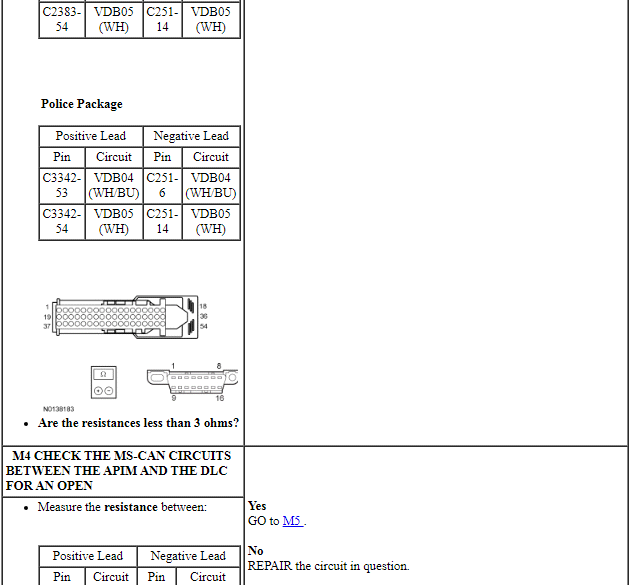
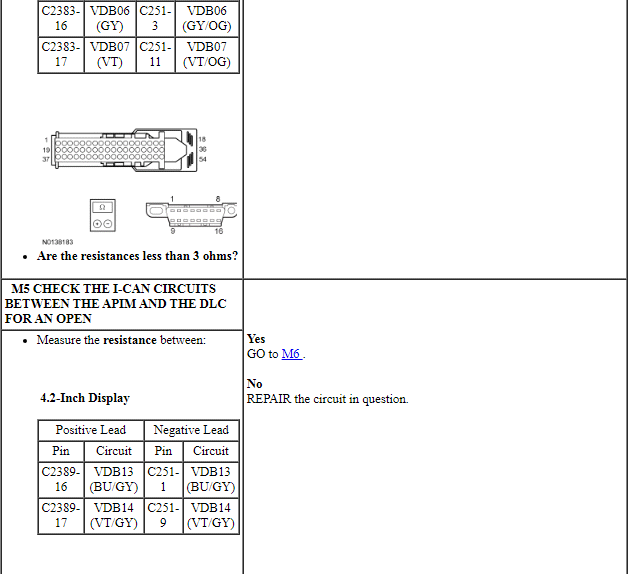
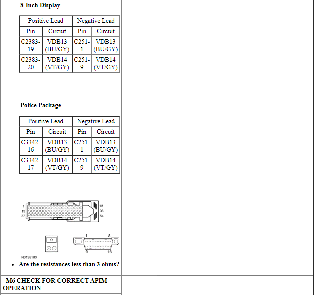
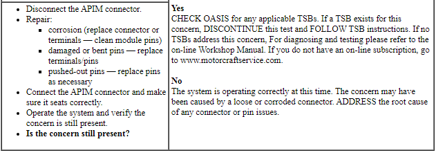
PINPOINT TEST M: THE APIM DOES NOT RESPOND TO THE SCAN TOOL
NOTE: Failure to disconnect the battery when instructed will result in false resistance readings. Refer to Section 414-01.
Pinpoint Test N: The Audio Front Control Module (ACM) Does Not Respond To The Scan Tool
Diagnostic Overview
Diagnostics in this manual assume a certain skill level and knowledge of Ford-specific diagnostic practices. Refer to Diagnostic Methods in Section 100-00 for information about these practices.
Refer to Wiring Diagrams Cell 14, Module Communications Network for schematic and connector information.
Refer to Wiring Diagrams Cell 130, Audio System/Navigation for schematic and connector information.
Normal Operation and Fault Conditions
The Audio Front Control Module (ACM) communicates with the scan tool through the High Speed Controller Area Network (HS-CAN). The IPC is used as the gateway module.
Visual Inspection and Diagnostic Pre-checks
Verify BCM fuse 29 (20A) is OK.
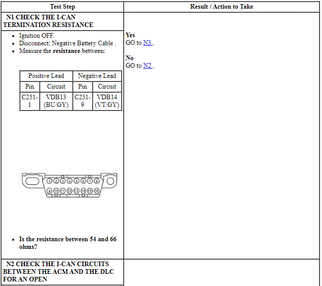
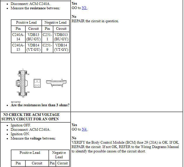
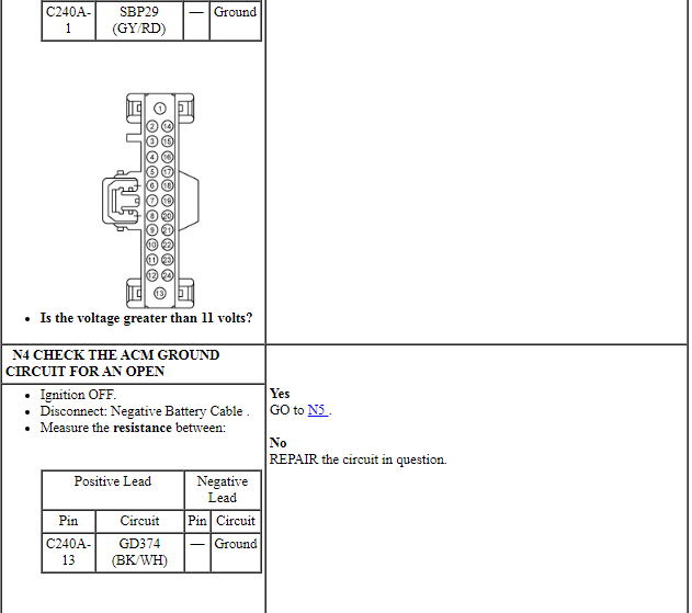
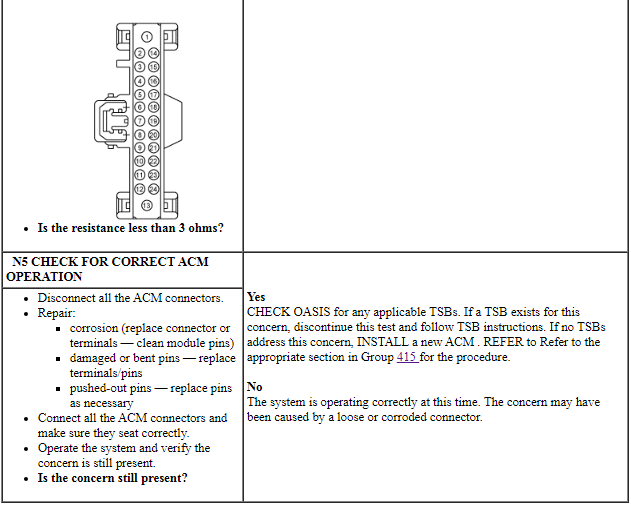
PINPOINT TEST N: THE ACM DOES NOT RESPOND TO THE SCAN TOOL
NOTE: Failure to disconnect the battery when instructed will result in false resistance readings. Refer to Section 414-01.
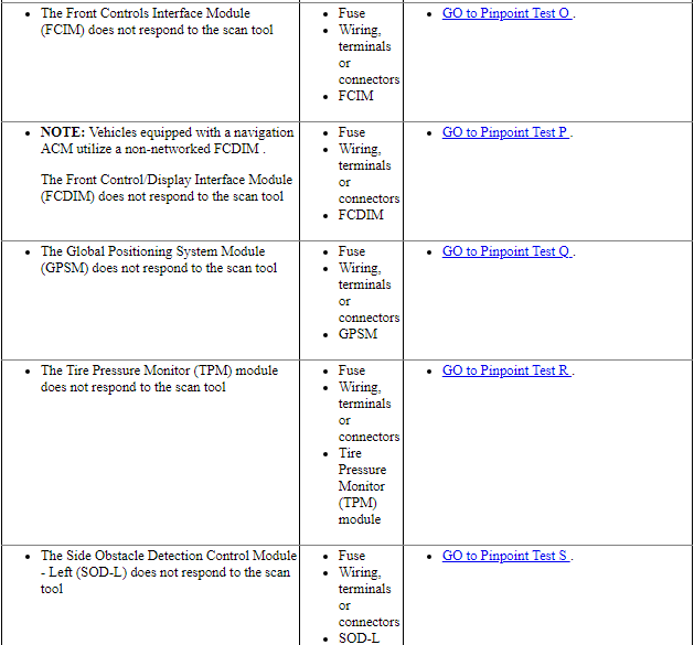
Pinpoint Test O: The Front Controls Interface Module (FCIM) Does Not Respond To The Scan Tool
Diagnostic Overview
Diagnostics in this manual assume a certain skill level and knowledge of Ford-specific diagnostic practices. Refer to Diagnostic Methods in Section 100-00 for information about these practices.
Refer to Wiring Diagrams Cell 14, Module Communications Network for schematic and connector information.
Refer to Wiring Diagrams Cell 130, Audio System/Navigation for schematic and connector information.
Normal Operation and Fault Conditions
The Front Controls Interface Module (FCIM) communicates with the scan tool through the High Speed Controller Area Network (HS-CAN). The IPC is used as a gateway module.
Visual Inspection and Diagnostic Pre-checks
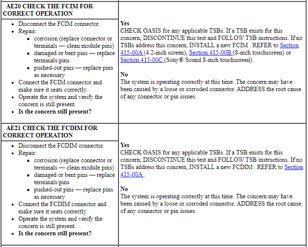
Verify BCM fuse 9 (10A) is OK.
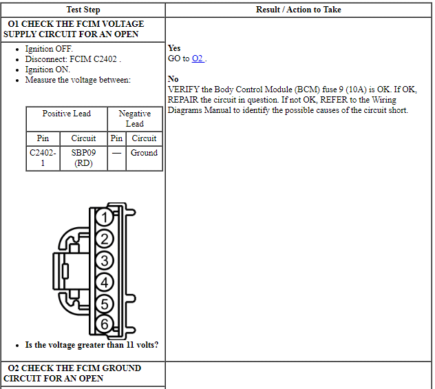
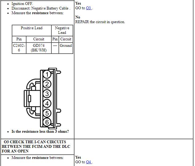
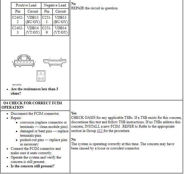
PINPOINT TEST O: THE FCIM DOES NOT RESPOND TO THE SCAN TOOL
NOTE: Failure to disconnect the battery when instructed will result in false resistance readings. Refer to Section 414-01.
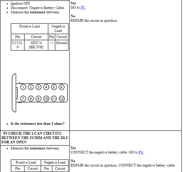
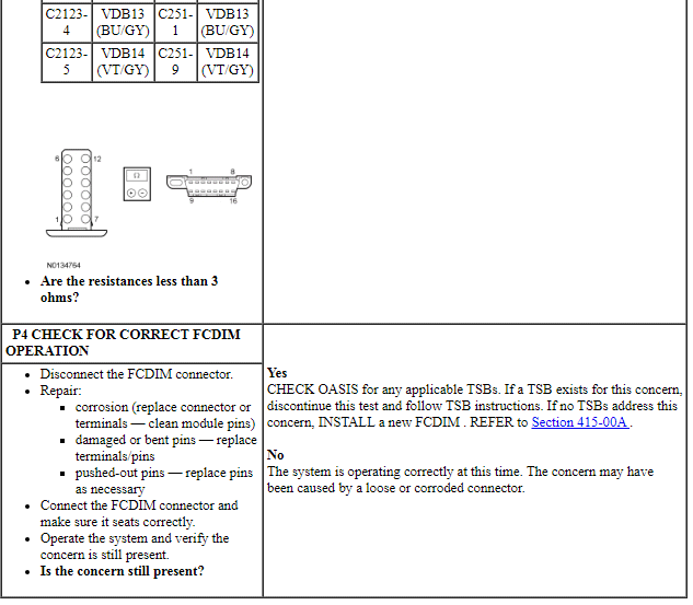
Pinpoint Test P: The Front Control/Display Interface Module (FCDIM) Does Not Respond To The Scan Tool
Diagnostic Overview
Diagnostics in this manual assume a certain skill level and knowledge of Ford-specific diagnostic practices. Refer to Diagnostic Methods in Section 100-00 for information about these practices.
Refer to Wiring Diagrams Cell 14, Module Communications Network for schematic and connector information.
Refer to Wiring Diagrams Cell 130, Audio System/Navigation for schematic and connector information.
Normal Operation and Fault Conditions
The Front Control/Display Interface Module (FCDIM) communicates with the scan tool through the Infotainment Controller Area Network (I-CAN). The IPC is used as the gateway module.
Visual Inspection and Diagnostic Pre-checks
Verify BCM fuse 9 (10A) is OK.
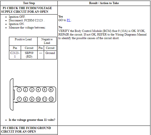
PINPOINT TEST P: THE FCDIM DOES NOT RESPOND TO THE SCAN TOOL
NOTE: Failure to disconnect the battery when instructed will result in false resistance readings. Refer to Section 414-01.
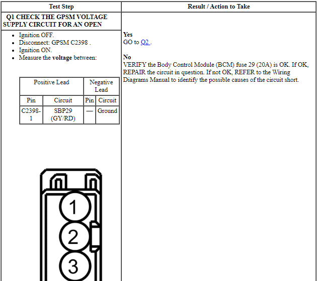
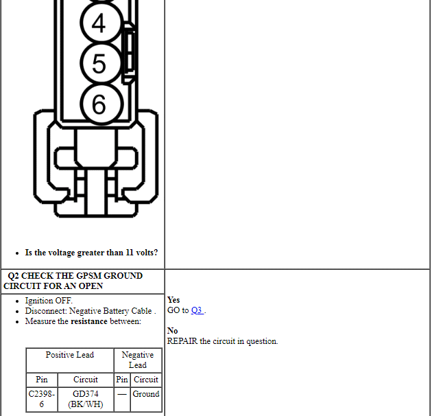
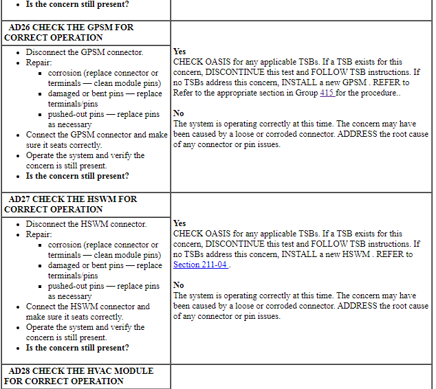
Pinpoint Test Q: The Global Positioning System Module (GPSM) Does Not Respond To The Scan Tool
Diagnostic Overview
Diagnostics in this manual assume a certain skill level and knowledge of Ford-specific diagnostic practices. Refer to Diagnostic Methods in Section 100-00 for information about these practices.
Refer to Wiring Diagrams Cell 14, Module Communications Network for schematic and connector information.
Refer to Wiring Diagrams Cell 130, Audio System/Navigation for schematic and connector information.
Normal Operation and Fault Conditions
The Global Positioning System Module (GPSM) communicates with the scan tool through the Medium Speed Controller Area Network (MS-CAN).
Visual Inspection and Diagnostic Pre-checks
Verify BCM fuse 29 (20A) is OK.
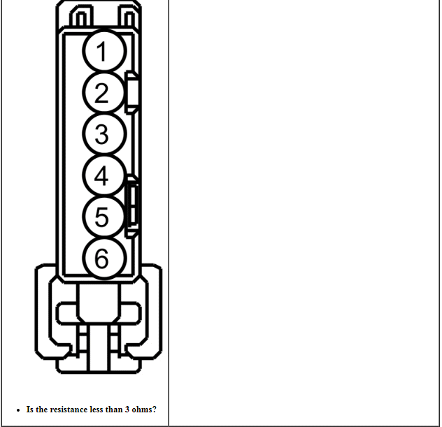
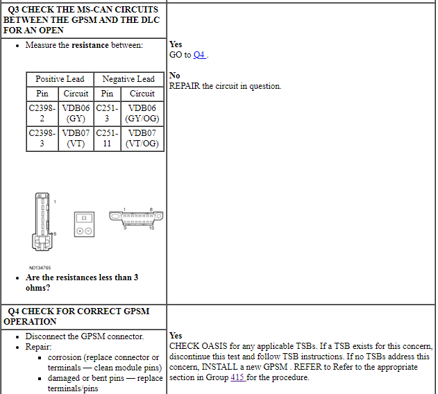
PINPOINT TEST Q: THE GPSM DOES NOT RESPOND TO THE SCAN TOOL
NOTE: Failure to disconnect the battery when instructed will result in false resistance readings. Refer to Section 414-01.
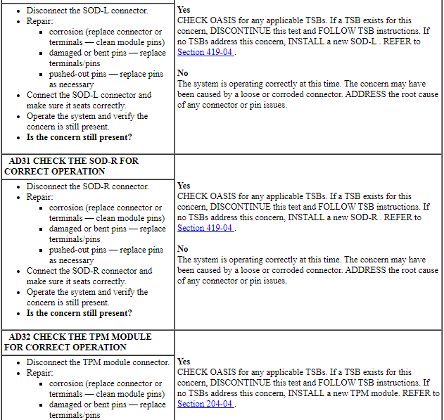
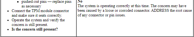
Pinpoint Test R: The Tire Pressure Monitor (TPM) Module Does Not Respond To The Scan Tool
Diagnostic Overview
Diagnostics in this manual assume a certain skill level and knowledge of Ford-specific diagnostic practices. Refer to Diagnostic Methods in Section 100-00 for information about these practices.
Refer to Wiring Diagrams Cell 14, Module Communications Network for schematic and connector information.
Refer to Wiring Diagrams Cell 118, Tire Pressure Monitor System for schematic and connector information.
Normal Operation and Fault Conditions
The Tire Pressure Monitor (TPM) module communicates with the scan tool through the Medium Speed Controller Area Network (MS-CAN).
Visual Inspection and Diagnostic Pre-checks
Verify Body Control Module (BCM) fuse 9 (10A) is OK.
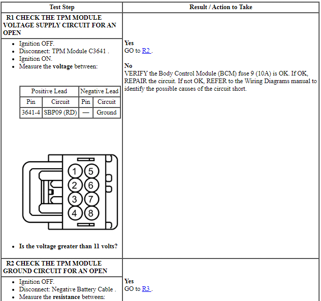
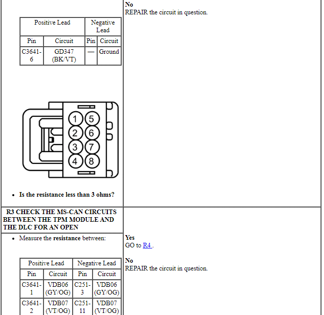
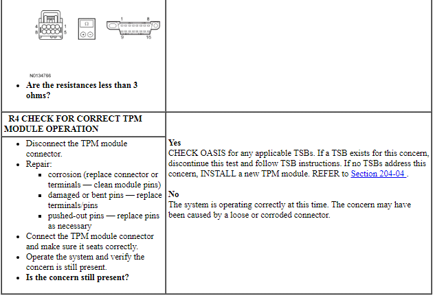
PINPOINT TEST R: THE TPM MODULE DOES NOT RESPOND TO THE SCAN TOOL
NOTE: Failure to disconnect the battery when instructed results in false resistance readings. Refer to Section 414-01.
Pinpoint Test S: The Side Obstacle Detection Control Module - Left (SOD-L) Does Not Respond To The Scan Tool
Diagnostic Overview
Diagnostics in this manual assume a certain skill level and knowledge of Ford-specific diagnostic practices. Refer to Diagnostic Methods in Section 100-00 for information about these practices.
Refer to Wiring Diagrams Cell 14, Module Communications Network for schematic and connector information.
Refer to Wiring Diagrams Cell 136, Vehicle Emergency Messaging System for schematic and connector information.
Normal Operation and Fault Conditions
The Side Obstacle Detection Control Module - Left (SOD-L) communicates with the scan tool through the Medium Speed Controller Area Network (MS-CAN).
Visual Inspection and Diagnostic Pre-checks
Verify BCM fuse 34 (10A) is OK.
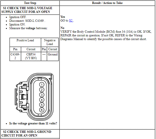
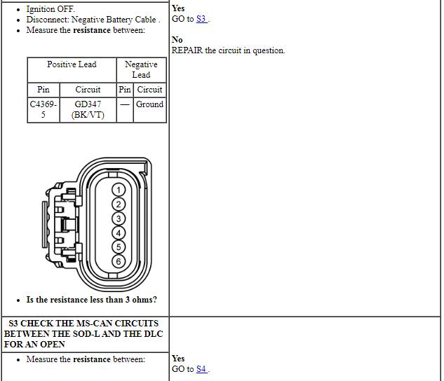
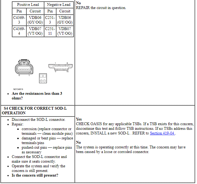
PINPOINT TEST S: THE SOD-L DOES NOT RESPOND TO THE SCAN TOOL
NOTE: Failure to disconnect the battery when instructed will result in false resistance readings. Refer to Section 414-01.
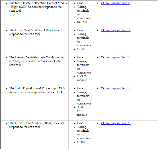
Pinpoint Test T: The Side Obstacle Detection Control Module - Right (SOD-R) Does Not Respond To The Scan Tool
Diagnostic Overview
Diagnostics in this manual assume a certain skill level and knowledge of Ford-specific diagnostic practices. Refer to Diagnostic Methods in Section 100-00 for information about these practices.
Refer to Wiring Diagrams Cell 14, Module Communications Network for schematic and connector information.
Refer to Wiring Diagrams Cell 136, Vehicle Emergency Messaging System for schematic and connector information.
Normal Operation and Fault Conditions
The Side Obstacle Detection Control Module - Right (SOD-R) communicates with the scan tool through the Medium Speed Controller Area Network (MS-CAN).
Visual Inspection and Diagnostic Pre-checks
Verify BCM fuse 34 (10A) is OK.
This pinpoint test is intended to diagnose the following:
- Fuse
- Wiring, terminals or connectors
- SOD-R
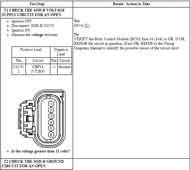
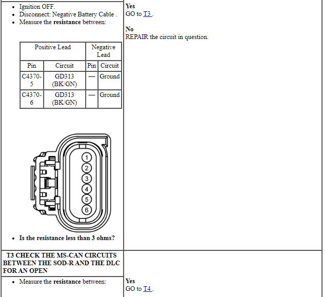
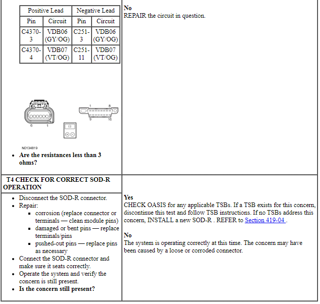
PINPOINT TEST T: THE SOD-R DOES NOT RESPOND TO THE SCAN TOOL
NOTE: Failure to disconnect the battery when instructed will result in false resistance readings. Refer to Section 414-01.
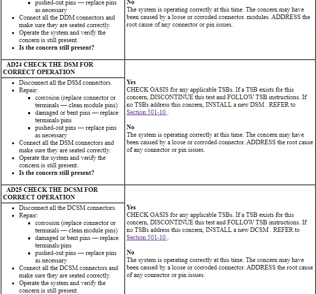
Pinpoint Test U: The Driver Seat Module (DSM) Does Not Respond To The Scan Tool
Diagnostic Overview
Diagnostics in this manual assume a certain skill level and knowledge of Ford-specific diagnostic practices. Refer to Diagnostic Methods in Section 100-00 for information about these practices.
Refer to Wiring Diagrams Cell 14, Module Communications Network for schematic and connector information.
Refer to Wiring Diagrams Cell 123, Memory Seats for schematic and connector information.
Normal Operation and Fault Conditions
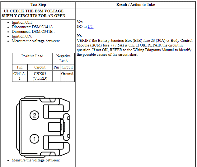
The Driver Seat Module (DSM) communicates with the scan tool through the Medium Speed Controller Area Network (MS-CAN).
Visual Inspection and Diagnostic Pre-checks
Verify Battery Junction Box (BJB) fuse 23 (30A) and Body Control Module (BCM) fuse 7 (7.5A) are OK.
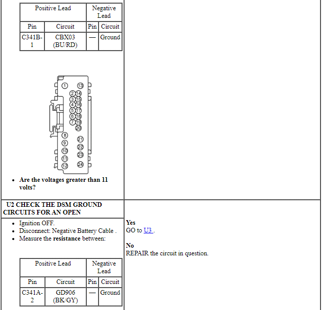
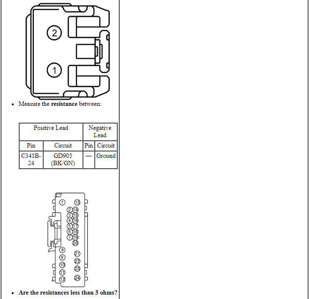
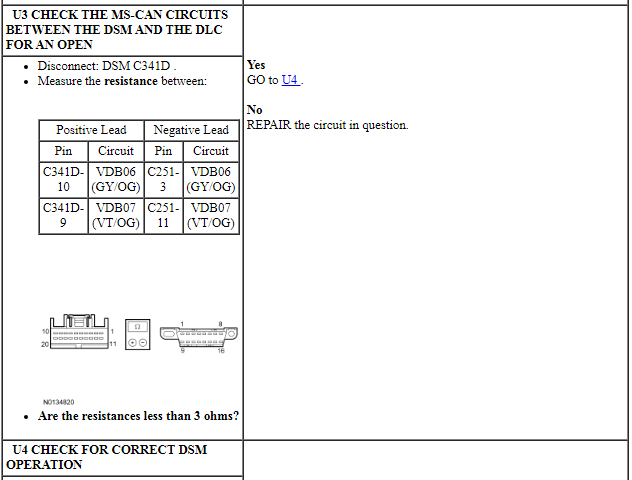
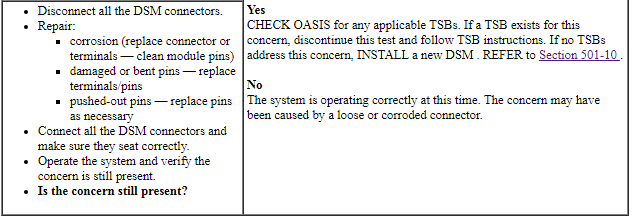
PINPOINT TEST U: THE DSM DOES NOT RESPOND TO THE SCAN TOOL
NOTE: Failure to disconnect the battery when instructed will result in false resistance readings. Refer to Section 414-01.
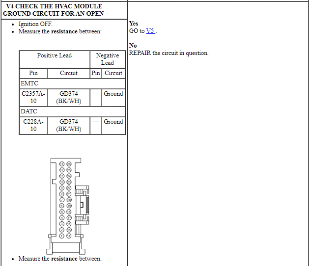
Pinpoint Test V: The Heating Ventilation Air Conditioning (HVAC) Module Does Not Respond To The Scan Tool
Diagnostic Overview
Diagnostics in this manual assume a certain skill level and knowledge of Ford-specific diagnostic practices. Refer to Diagnostic Methods in Section 100-00 for information about these practices.
Refer to Wiring Diagrams Cell 14, Module Communications Network for schematic and connector information.
Refer to Wiring Diagrams Cell 54, Manual Climate Control System for schematic and connector information.
Refer to Wiring Diagrams Cell 55, Automatic Climate Control System for schematic and connector information.
Normal Operation and Fault Conditions
The HVAC module communicates with the scan tool through the Medium Speed Controller Area Network (MS-CAN).
Visual Inspection and Diagnostic Pre-checks
Verify BCM fuse 46 (10A) is OK
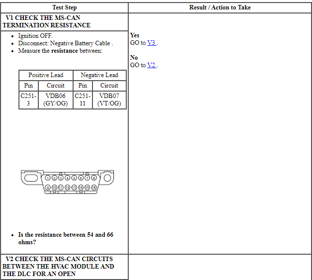
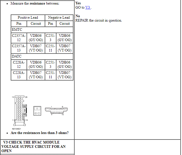
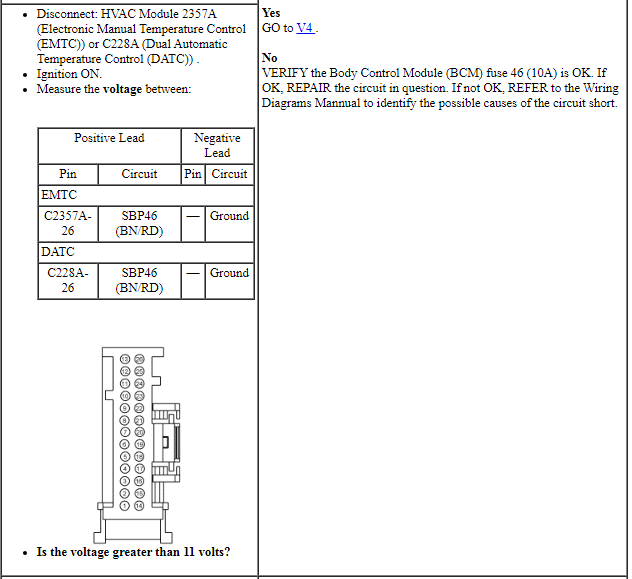
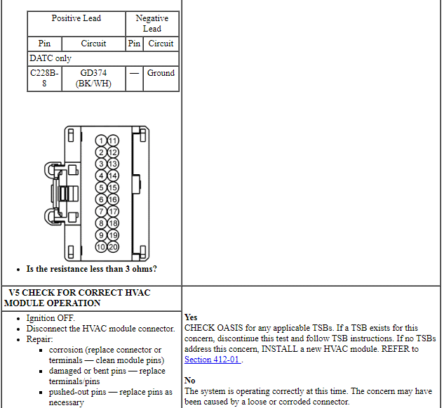
PINPOINT TEST V: THE HVAC MODULE DOES NOT RESPOND TO THE SCAN TOOL
NOTE: Failure to disconnect the battery when instructed will result in false resistance readings. Refer to Section 414-01.
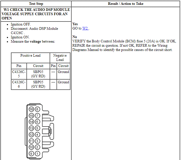
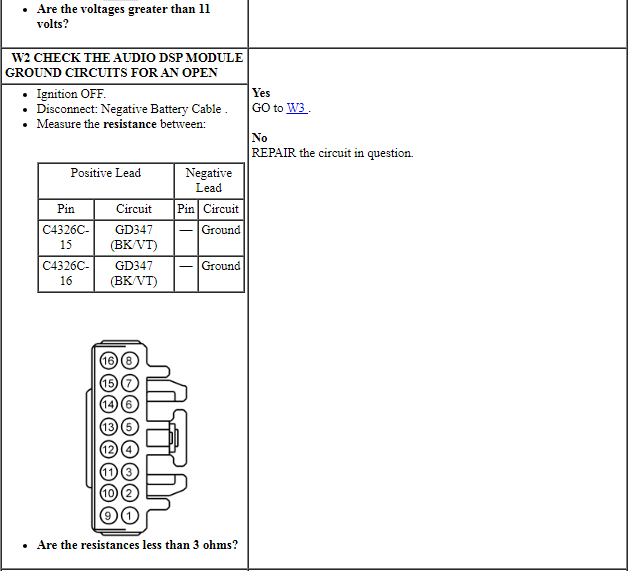
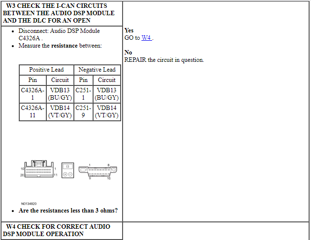
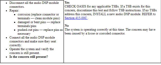
Pinpoint Test W: The Audio Digital Signal Processing (DSP) Module Does Not Respond To The Scan Tool
Diagnostic Overview
Diagnostics in this manual assume a certain skill level and knowledge of Ford-specific diagnostic practices. Refer to Diagnostic Methods in Section 100-00 for information about these practices.
Refer to Wiring Diagrams Cell 14, Module Communications Network for schematic and connector information.
Refer to Wiring Diagrams Cell 130, Audio System/Navigation for schematic and connector information.
Normal Operation and Fault Conditions
The audio Digital Signal Processing (DSP) module communicates with the scan tool through the High Speed Controller Area Network (HS-CAN). The IPC is used as a gateway module.
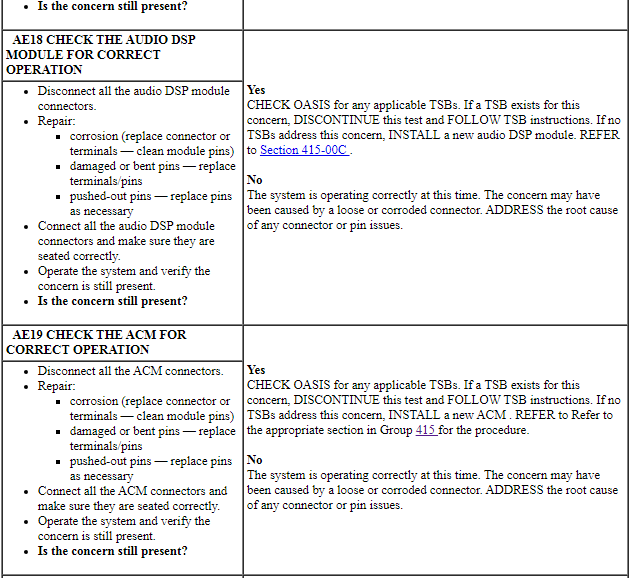
Visual Inspection and Diagnostic Pre-checks
Verify BCM fuse 5 (20A) is OK.
PINPOINT TEST W: THE AUDIO DSP MODULE DOES NOT RESPOND TO THE SCAN TOOL
NOTE: Failure to disconnect the battery when instructed will result in false resistance readings. Refer to Section 414-01.
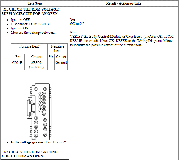
Pinpoint Test X: The Driver Door Module (DDM) Does Not Respond To The Scan Tool
Diagnostic Overview
Diagnostics in this manual assume a certain skill level and knowledge of Ford-specific diagnostic practices. Refer to Diagnostic Methods in Section 100-00 for information about these practices.
Refer to Wiring Diagrams Cell 14, Module Communications Network for schematic and connector information.
Refer to Wiring Diagrams Cell 124, Power Mirrors for schematic and connector information.
Normal Operation and Fault Conditions
The Driver Door Module (DDM) communicates with the scan tool through the Medium Speed Controller Area Network (MS-CAN).
Visual Inspection and Diagnostic Pre-checks
Verify BCM fuse 7 (7.5A) is OK.
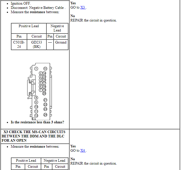
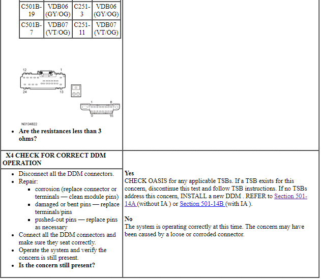
PINPOINT TEST X: THE DDM DOES NOT RESPOND TO THE SCAN TOOL
NOTE: Failure to disconnect the battery when instructed will result in false resistance readings. Refer to Section 414-01.
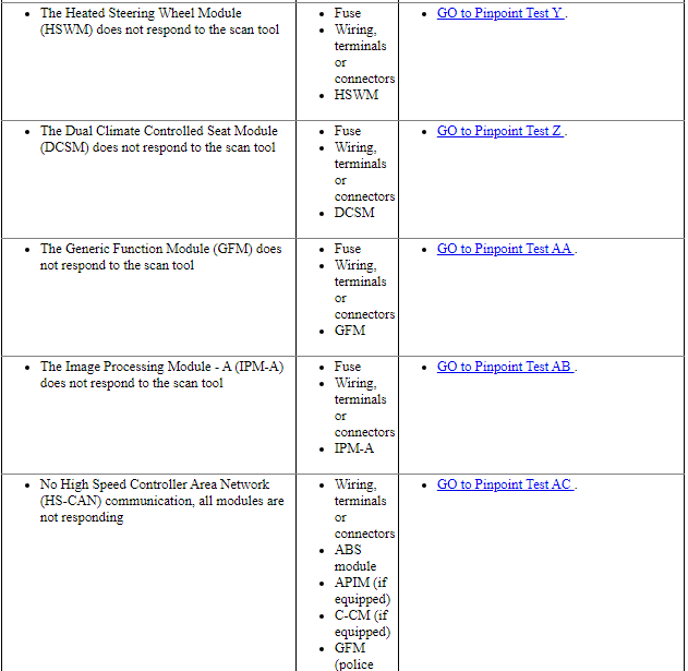
Pinpoint Test Y: The Heated Steering Wheel Module (HSWM) Does Not Respond To The Scan Tool
Diagnostic Overview
Diagnostics in this manual assume a certain skill level and knowledge of Ford-specific diagnostic practices. Refer to Diagnostic Methods in Section 100-00 for information about these practices.
Refer to Wiring Diagrams Cell 14, Module Communications Network for schematic and connector information.
Refer to Wiring Diagrams Cell 128, Adjustable Steering Column for schematic and connector information.
Normal Operation and Fault Conditions
TheHeated Steering Wheel Module (HSWM) communicates with the scan tool through the Medium Speed Controller Area Network (MS-CAN).
Visual Inspection and Diagnostic Pre-checks
Verify Body Control Module (BCM) fuse 36 (10A) is OK.
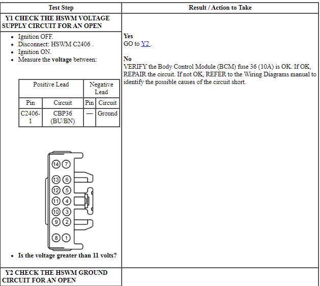
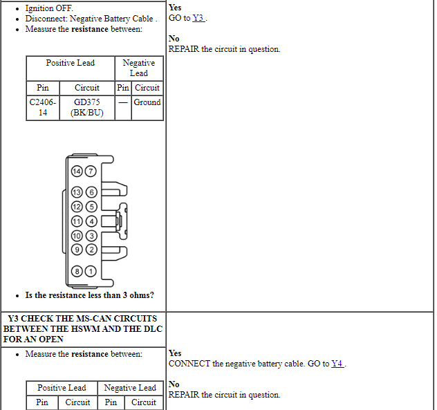
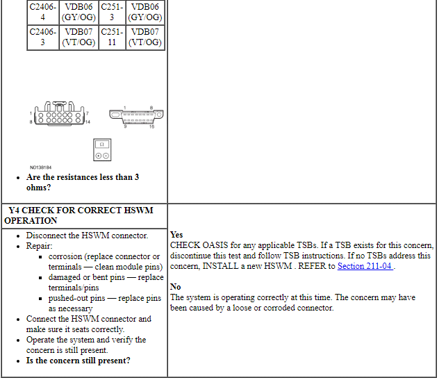
PINPOINT TEST Y: THE HSWM DOES NOT RESPOND TO THE SCAN TOOL
NOTE: Failure to disconnect the battery when instructed results in false resistance readings. Refer to Section 414-01.
Pinpoint Test Z: The Dual Climate Controlled Seat Module (DCSM) Does Not Respond To The Scan Tool
Diagnostic Overview
Diagnostics in this manual assume a certain skill level and knowledge of Ford-specific diagnostic practices. Refer to Diagnostic Methods in Section 100-00 for information about these practices.
Refer to Wiring Diagrams Cell 14, Module Communications Network for schematic and connector information.
Refer to Wiring Diagrams Cell 119, Climate Controlled Seats for schematic and connector information.
Normal Operation and Fault Conditions
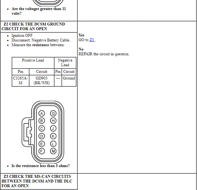
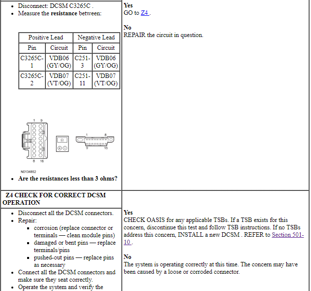
The Dual Climate Controlled Seat Module (DCSM) communicates with the scan tool through the Medium Speed Controller Area Network (MS-CAN).
Visual Inspection and Diagnostic Pre-checks
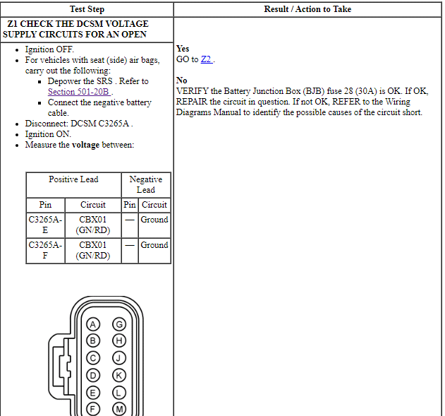
Verify BJB fuse 28 (30A) is OK.
PINPOINT TEST Z: PINPOINT TEST P: THE DCSM DOES NOT RESPOND TO THE SCAN TOOL
NOTE: If a seat equipped with a Supplemental Restraint System (SRS) component is being serviced, the SRS must be depowered. Refer to Section 501-20B.
NOTE: Failure to disconnect the battery when instructed will result in false resistance readings. Refer to Section 414-01.

Pinpoint Test AA: The Generic Function Module (GFM) Does Not Respond To The Scan Tool
Diagnostic Overview
Diagnostics in this manual assume a certain skill level and knowledge of Ford-specific diagnostic practices. Refer to Diagnostic Methods in Section 100-00 for information about these practices.
Refer to Wiring Diagrams Cell 14, Module Communications Network for schematic and connector information.
Refer to Wiring Diagrams Cell 96, Police Option for schematic and connector information.
Normal Operation and Fault Conditions
The GFM communicates with the scan tool through the High Speed Controller Area Network (HS-CAN).
Visual Inspection and Diagnostic Pre-checks
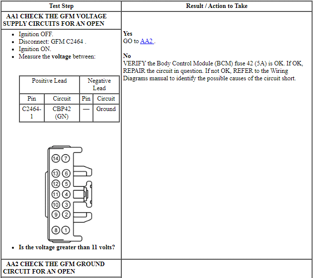
Verify Body Control Module (BCM) fuse 42 (5A) is OK.
PINPOINT TEST AA: THE GFM DOES NOT RESPOND TO THE SCAN TOOL
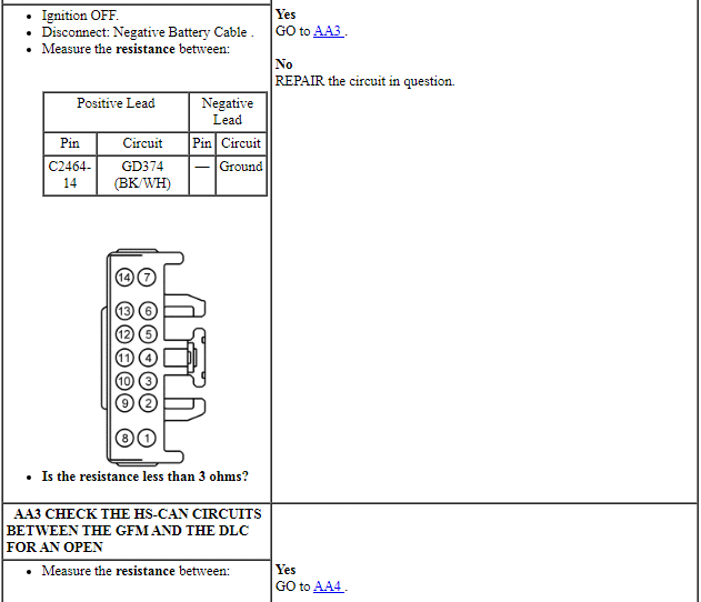
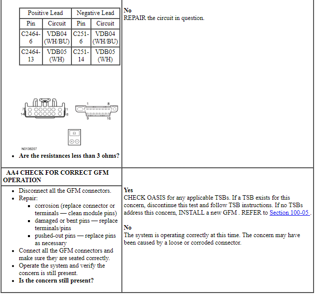
NOTE: Failure to disconnect the battery when instructed results in false resistance readings. Refer to Section 414-01.
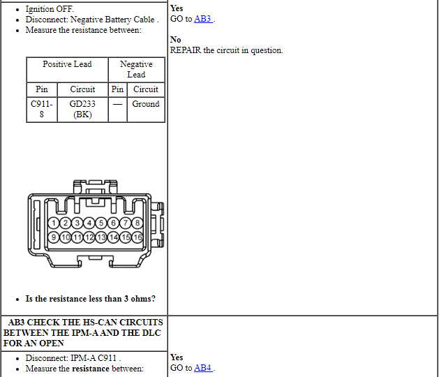
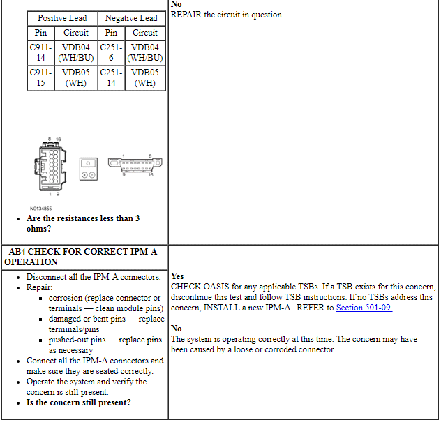
Pinpoint Test AB: The Image Processing Module - A (IPM-A) Does Not Respond To The Scan Tool
Diagnostic Overview
Diagnostics in this manual assume a certain skill level and knowledge of Ford-specific diagnostic practices. Refer to Diagnostic Methods in Section 100-00 for information about these practices.
Refer to Wiring Diagrams Cell 14, Module Communications Network for schematic and connector information.
Refer to Wiring Diagrams Cell 124, Power Mirrors for schematic and connector information.
Normal Operation and Fault Conditions
The IPM-A communicates with the scan tool through the High Speed Controller Area Network (HS-CAN).
Visual Inspection and Diagnostic Pre-checks
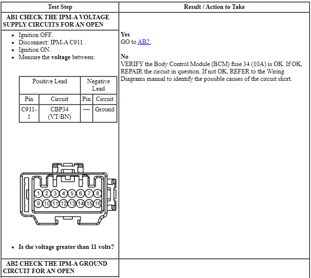
Verify Body Control Module (BCM) fuse 34 (10A) is OK.
PINPOINT TEST AB: THE IPM-A DOES NOT RESPOND TO THE SCAN TOOL
NOTE: Failure to disconnect the battery when instructed results in false resistance readings. Refer to Section 414-01.
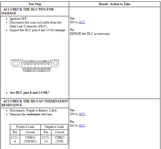
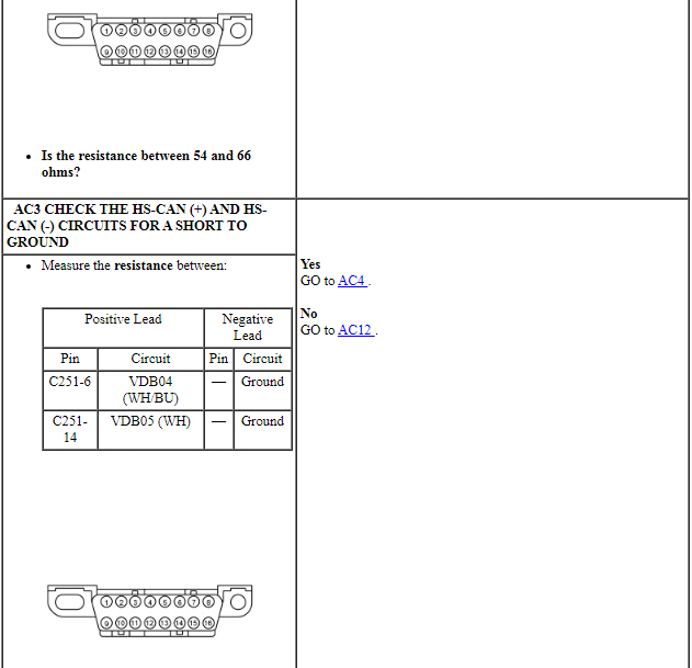
Pinpoint Test AC: No High Speed Controller Area Network (HS-CAN) Communication, All Modules Are Not Responding
Diagnostic Overview
Diagnostics in this manual assume a certain skill level and knowledge of Ford-specific diagnostic practices. Refer to Diagnostic Methods in Section 100-00 for information about these practices.
Refer to Wiring Diagrams Cell 14, Module Communications Network for schematic and connector information.
Normal Operation and Fault Conditions
REFER to Communications Network.
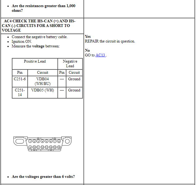
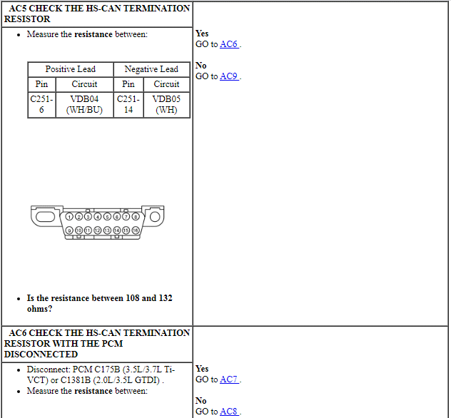
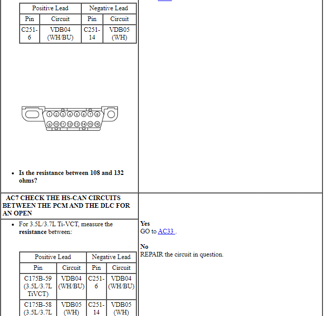
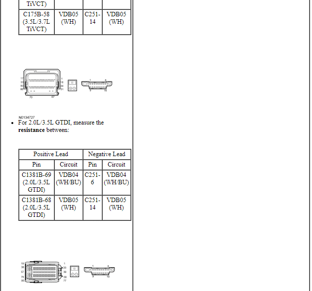
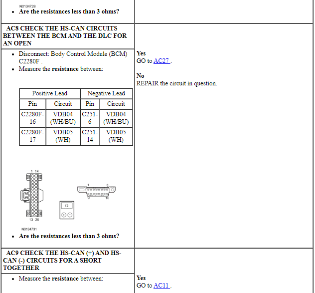
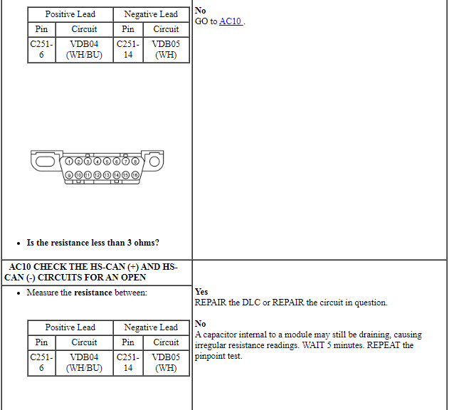
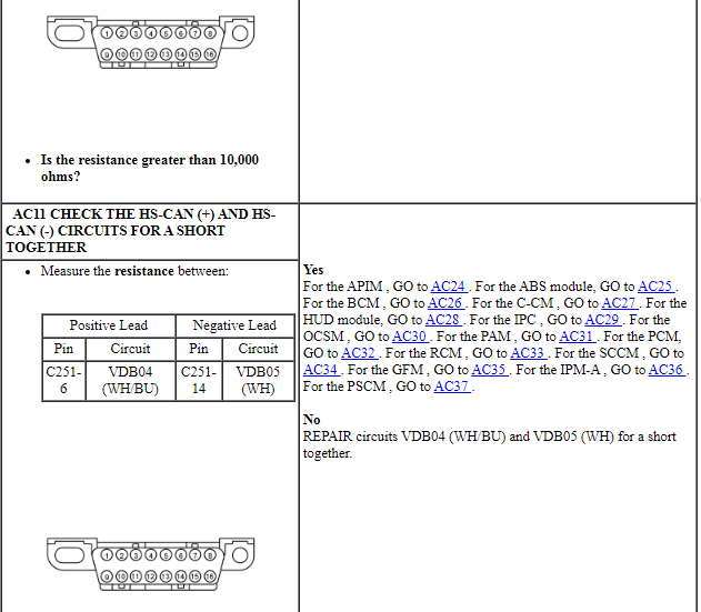
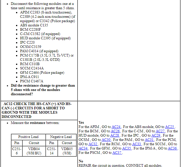
PINPOINT TEST AC: NO HS-CAN COMMUNICATION, ALL MODULES ARE NOT RESPONDING
NOTE: Various modules set network DTCs during this test procedure. Clear DTCs from all modules after completing the diagnostic procedure.
NOTE: Failure to disconnect the battery when instructed results in false resistance readings. Refer to Section 414-01.
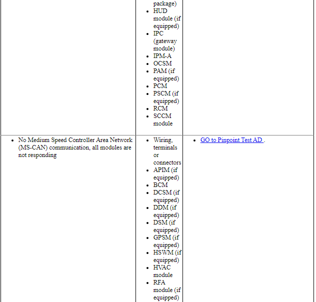
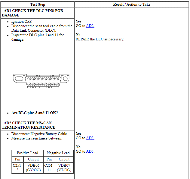
Pinpoint Test AD: No Medium Speed Controller Area Network (MS-CAN) Communication, All Modules Are Not Responding
Diagnostic Overview
Diagnostics in this manual assume a certain skill level and knowledge of Ford-specific diagnostic practices. Refer to Diagnostic Methods in Section 100-00 for information about these practices.
Refer to Wiring Diagrams Cell 14, Module Communications Network for schematic and connector information.
Normal Operation and Fault Conditions
REFER to Communications Network.
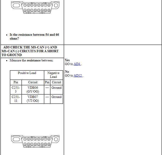
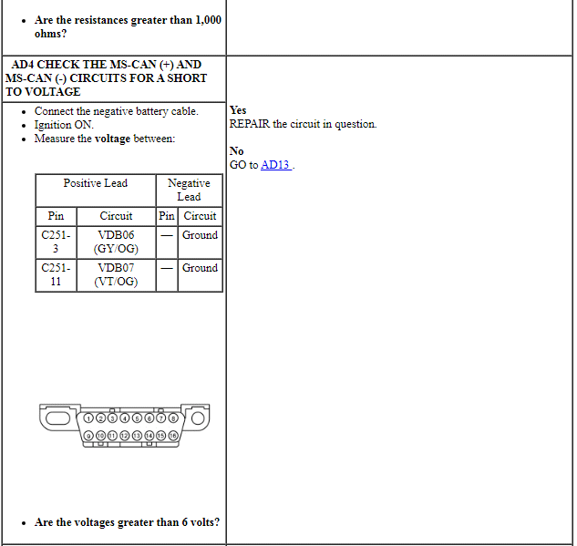
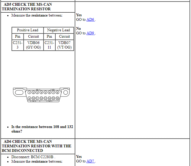
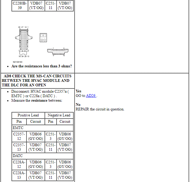
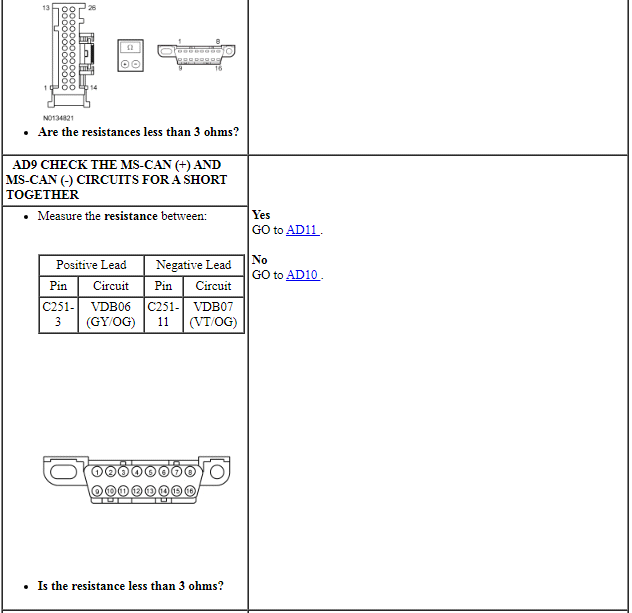
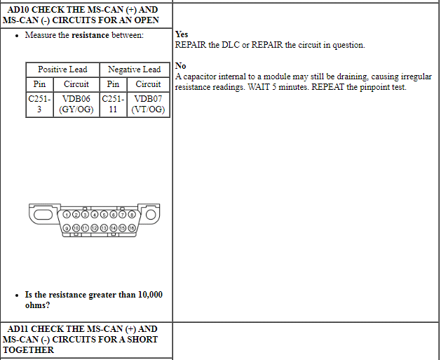
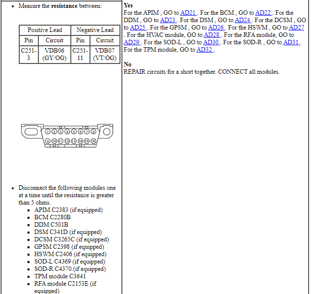
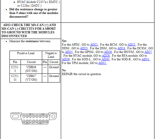
PINPOINT TEST AD: NO MS-CAN COMMUNICATION, ALL MODULES ARE NOT RESPONDING
NOTE: Various modules set network DTCs during this test procedure. Clear DTCs from all modules after completing the diagnostic procedure.
NOTE: Failure to disconnect the battery when instructed results in false resistance readings. Refer to Section 414-01.

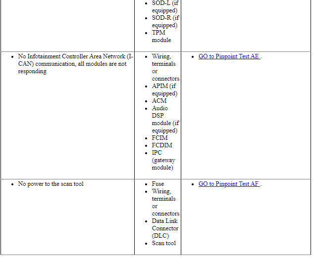
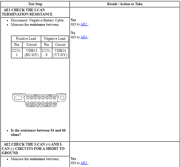
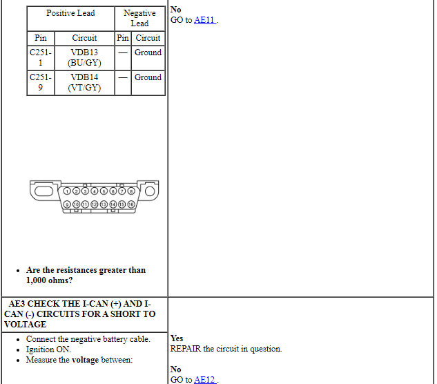
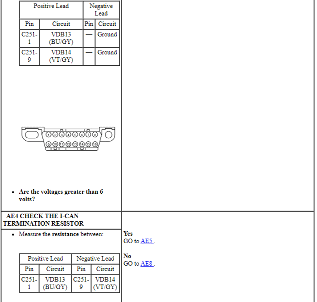
Pinpoint Test AE: No Infotainment Controller Area Network (I-CAN) Communication, All Modules Are Not Responding
Diagnostic Overview
Diagnostics in this manual assume a certain skill level and knowledge of Ford-specific diagnostic practices. Refer to Diagnostic Methods in Section 100-00 for information about these practices.
Refer to Wiring Diagrams Cell 14, Module Communications Network for schematic and connector information.
Normal Operation and Fault Conditions
REFER to Communications Network.
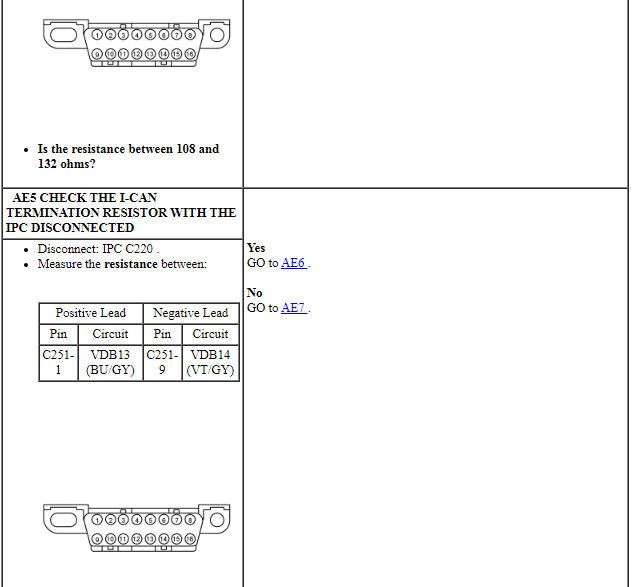
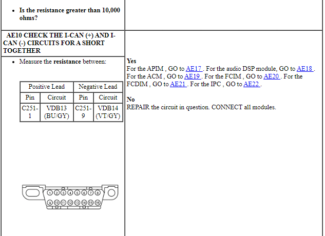
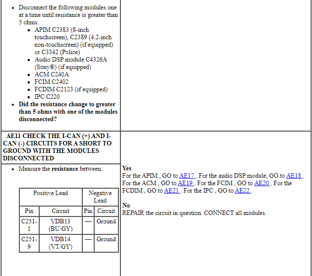
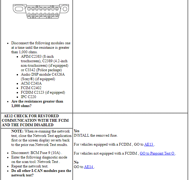
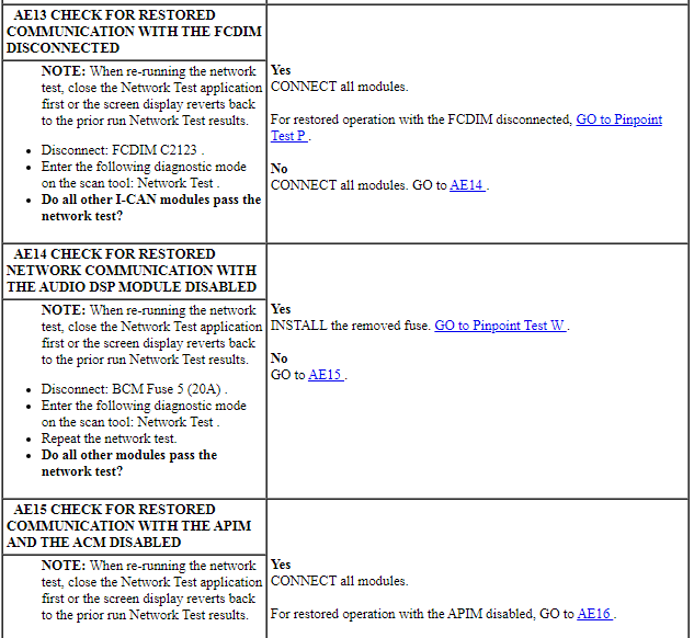
PINPOINT TEST AE: NO I-CAN COMMUNICATION, ALL MODULES ARE NOT RESPONDING
NOTE: Various modules set network DTCs during this test procedure. Clear DTCs from all modules after completing the diagnostic procedure.
NOTE: Failure to disconnect the battery when instructed results in false resistance readings. Refer to Section 414-01.
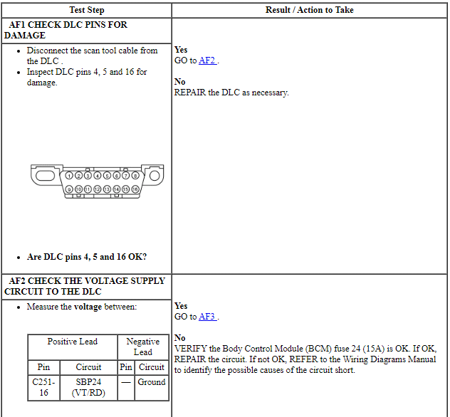
Pinpoint Test AF: No Power To The Scan Tool
Diagnostic Overview
Diagnostics in this manual assume a certain skill level and knowledge of Ford-specific diagnostic practices. Refer to Diagnostic Methods in Section 100-00 for information about these practices.
Refer to Wiring Diagrams Cell 14, Module Communications Network for schematic and connector information.
Normal Operation and Fault Conditions
The scan tool is connected to the Data Link Connector (DLC) to communicate with modules on the High Speed Controller Area Network (HS-CAN) and Medium Speed Controller Area Network (MS-CAN).
A loss of ground or poor ground at the DLC may result in HS-CAN or MS-CAN faults while the scan tool is connected.
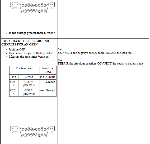
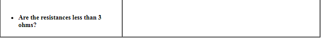
PINPOINT TEST AF: NO POWER TO THE DLC
NOTE: Failure to disconnect the battery when instructed will result in false resistance readings. Refer to Section 414-01.

 Module Configuration
DESCRIPTION AND OPERATION
Module Configuration
System Operation
Programmable Module Installation (PMI)
Programmable Module Installation (PMI) is a scan tool process which
configures settings in a new ...
Other materials:
Noise, Vibration and Harshness (NVH) - Diagnosis and Testing
Special Tool(s)
Diagnostic Theory
The shortest route to an accurate diagnosis results from:
system knowledge, including comparison with a known good system.
system history, including repair history and usage patterns.
condition history, especially any relationship to repairs or sudden
change ...
Specifications, Description and Operation
SPECIFICATIONS
Torque Specifications
DESCRIPTION AND OPERATION
Rear View Mirrors
Exterior, Power
Overview
Power mirrors allow the LH and RH exterior mirror glass to be positioned
electronically. The position of the power mirror glass is controlled by the
exterior mirror control switch. Selecting ...
Satellite radio information
Satellite Radio Channels
Sirius broadcasts a variety of music, news, sports, weather, traffic and
entertainment satellite radio channels. For more information and a
complete list of Sirius satellite radio channels, visit www.siriusxm.com in
the United States, www.sirius.ca in Canada, or call Sir ...
