Headlamp Adjustment
Special Tool(s)
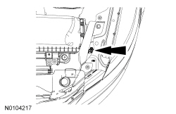
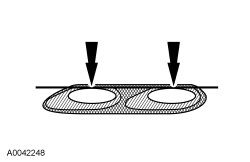
Headlamp Adjustment Screw Location
Headlamp Aiming
- The headlamp aiming procedure depends on what type of beam pattern the
headlamp is equipped with. Vehicles may come equipped with visually
optically aligned left (VOL) or visually optically aligned right (VOR)
headlamps. To identify the headlamp beam pattern, look on the headlamp lens.
Molded in small letters on the headlamp lens is one of the following:
- VOL and SAE
- VOR and SAE
- NOTE: Mechanical aimers cannot be used with VOR- or VOL-type
headlamps.
Once the headlamp beam pattern is identified, aim the headlamps using one of the following methods:
- Photometric aimers can aim VOL- and VOR- headlamps. This is the preferred method of headlamp aiming.
- Visual or screen method aiming can be used to aim VOL- and VOR- headlamps.
Photometric Aiming
- For the photometric aiming procedure, refer to the appropriate photometric headlamp aimer instruction manual.
Screen Method Aiming
All headlamp types
NOTE: Horizontal aim is not adjustable.
NOTE: Consult your state vehicle inspection manual for recommended tolerance ranges for visual aiming.
- Before starting headlamp adjustment:
- check that the vehicle is on level ground.
- check the tire inflation.
- check that no other load is in the vehicle other than a half tank of fuel.
- check that the headlamps are clean.
- check for correct headlamp operation.
- if the vehicle is equipped with air suspension, make sure that the switch is on.
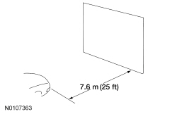
- NOTE: The vertical wall or screen must be a minimum of 2.4 m (8
ft) wide.
Park the vehicle on a level surface approximately 7.6 m (25 ft) from the vertical wall or screen directly in front of it.
- NOTE: The center of the lamp is marked either on the lens
(circle, crosshair or other mark) or on the bulb shield internal to the lamp
(crosshair or other mark).
Mark a horizontal reference line on the vertical wall or screen.
- Measure the center of the headlamp height to ground and record the measurement.
- Make a 2.4 m (8 ft) horizontal mark (using masking tape) on the vertical wall or screen at the same distance from the ground as previously recorded.
- NOTE: This procedure should be done in a dark environment to
effectively see the headlamp beam pattern.
Turn on the low beam headlamps to illuminate the wall or screen and open the hood.
- On the wall or screen, locate the high intensity area of the beam pattern.
VOR-type headlamps
- NOTE: The appearance of the VOR beam pattern may vary between
vehicles.
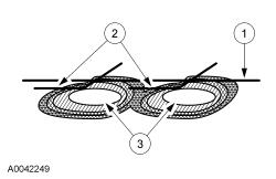
Identify at the top edge of this high intensity area a distinct horizontal cutoff in the beam pattern. If the top edge of this cutoff is not even with the horizontal reference line, the headlamp beam needs to be adjusted using the headlamp adjusting screw.
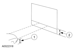
VOL-type headlamps
- There is a distinct cutoff in the left portion of the beam pattern. The
edge of this cutoff should be positioned 50.2 mm (2 in) below the horizontal
reference line. Adjust the headlamp as necessary using the headlamp
adjusting screw.
- Horizontal reference line.
- Top edge of the beam pattern.
- High intensity zone.
Autolamps Time Delay Adjustment
NOTE: The time delay can be programmed through the message center using the message center buttons (if equipped) or using the following steps.
NOTE: Steps 2 through 5 must be carried out within a 10-second period.
- Start with the ignition switch off and the headlamp switch in the AUTOLAMPS ON position.
- Place the headlamp switch in the OFF position.
- Place the ignition switch in the RUN position.
- Place the ignition switch in the OFF position.
- Place the headlamp switch in the AUTOLAMPS ON position. The exterior lamps turn on at this point.
- Wait the desired amount of time and place the headlamp switch in the OFF position (maximum of 3 minutes). The exterior lamps turn off and the autolamp time delay is now set.
Automatic High Beam Sensitivity Adjustment
NOTE: This procedure switches between the 2 available sensitivity settings (near and far) and provides user feedback by cycling the high beams.
NOTE: The sensitivity setting can also be changed using the scan tool.
NOTE: The battery must be within normal operating range or the setting change may not take effect.
- Preconditions must be met before the automatic high beam sensitivity
setting can be changed. Make sure:
- the vehicle is in PARK (P)
- the ignition is in RUN
- the headlamp switch is in the HEADLAMPS ON position
- the low beams are on (high beams are off)
- Cycle the headlamp switch from the HEADLAMPS ON to the AUTOLAMPS position 3 times within 2 seconds, ending with the HEADLAMPS ON position.
- Cycle the flash-to-pass feature 3 times.
- The high beams cycle on then off automatically to confirm the sensitivity level has changed.
 Diagnosis and Testing
Exterior Lighting
DTC Charts
Diagnostics in this manual assume a certain skill level and knowledge of
Ford-specific diagnostic practices. Refer to Diagnostic Methods in Section
100-00 ...
 Removal and Installation
Headlamp Assembly
Removal
Remove the front bumper cover. Refer to Section 501-19.
Remove the headlamp assembly upper bolt.
To install, tighten to 3.2 Nm (28 lb-in).
Remove the h ...
Other materials:
Engine block heater
WARNING: Failure to follow engine block heater instructions
could result in property damage or physical injury.
WARNING: Do not use your heater with ungrounded electrical
systems or two-pronged (cheater) adapters. There is a risk of
electrical shock.
Note: The heater is most effective when outd ...
General Procedures
Remote Keyless Entry (RKE) Transmitter Programming
NOTE: The Remote Keyless Entry (RKE) transmitter of the Integrated
Keyhead Transmitter (IKT) is programmed automatically during the Passive
Anti-Theft System (PATS) programming. For information on programming
the IKT keys, refer to ...
Fuel Charging and Controls - Turbocharger, 2.0L GTDI
SPECIFICATIONS
Torque Specifications
a Refer to the procedure in this section.
DESCRIPTION AND OPERATION
Turbocharger
Component Location
Overview
NOTICE: Whenever turbocharger air intake system components are
removed, always cover open ports to protect from debris. It is important that ...
