Window Grid Wire Repair
General Equipment
Material
NOTE: The grid line material is not embedded into the glass, but is baked to the glass surface and consequently can be scraped off. An undamaged grid line will have small ridges that project above the surface of the glass and can easily be felt when running a fingernail across them. Grid lines that have been "razor bladed" will feel smooth when a fingernail is dragged across the affected area. Inoperative lines may appear to the eye to be undamaged due to residue remaining on the glass and will require diagnosis with a voltmeter or 12V test lamp. For additional information, refer to Diagnosis and Testing in this section.
- Bring the vehicle up to a room temperature of at least 16┬║C (60┬║F) or above.
- NOTICE: Do not use scrapers, sharp instruments or abrasive
window cleaners on the interior surface of the rear window glass as this may
cause damage to the grid lines.
Clean the entire grid line repair area with glass cleaner and 0000 steel wool to remove all dirt, wax, grease, oil or other foreign material.
- Mark the location of the grid break on the exterior of the rear window glass.
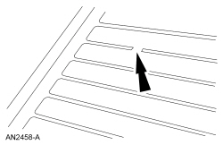
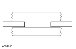
- Using a polypropylene film fine line tape, mask the area directly above and below the grid break extending the tape 26 mm (1.02 in) beyond the concern area in both directions. The break area should be at the center of the mask.
- NOTE: If the brown layer is not broken or missing, apply only the
silver grid repair compound to the break. If both the brown and silver
layers of the grid are broken or missing, apply a coating of the lacquer
touch up paint across the break in the grid line prior to applying the rear
window defroster repair compound. Do not overlap the silver grid line with
the paint. Several applications may be necessary to achieve a color match.
NOTE: Allow at least 5 minutes of drying time between applications for the touch up paint or the silver repair coating. Applying fewer coats or not allowing adequate drying time between coats will produce repaired resistance that is greater than OEM resistance, resulting in poor defrost performance and excessive localized heating.
Apply the repair coating to the grid break area in several smooth, continuous strokes. Extend the silver repair coating at least 6.35 mm (0.25 in) on both sides of the break area.
Apply a minimum of 6 applications of the grid repair compound.
- NOTE: The repair coating air-dries in approximately one minute
and can be energized after 5 minutes. Optimum adhesion occurs after
approximately 24 hours.
Allow the repair area to dry completely and remove the mask.
- NOTICE: Be careful not to damage the grid line with the razor
blade. If this occurs, additional repair may be necessary.
Remove any excess repair compound above or below the grid line with a razor blade.
- NOTE: The interior side of the grid lines are not painted, but
due to the silver tarnishing will tend to change the grid to a gold or brown
color. The repair area will be bright silver and will also tarnish over time
to match the rest of the grid.
Test the system for normal operation.
Lead Terminal Repair
General Equipment

Material
- Bring the vehicle up to room temperature of at least 16┬║C (60┬║F) or above.
- NOTE: The new terminal will cover the original terminal location,
but it must be placed so that the terminal conductive areas will be placed
on a good conductive base.
Clean the bus bar in the area to be repaired with steel wool (000 to 0000 grade), and then with glass cleaner to remove all dirt, wax, grease, oil or other foreign material.
- NOTICE: Do not use any type of flame torch or flame-heated
soldering gun for this procedure. Use of these tools provide inadequate heat
generation at the tip and the exhaust heat can cause damage to plastic trim
parts in the area. Use only an electric soldering gun with 100 watts or more
of power. Before using the soldering gun, be sure to melt a small amount of
rosin core solder to the tip. The solder will assist in achieving better
heat transfer from the soldering gun tip to the new terminal.
NOTE: Depending on the original terminal location, and whether the terminal is covered by pillar trim, will determine where to locate the new terminal. Some grid line bus bars may only allow the placement of the terminal above or below the original tab location due to space limitations. For most vehicle applications, the replacement tab location will cover the original tab location, but still allow the replacement tab to attach to the bus bar on good conductive material.
Place the replacement terminal type A over the original tab location, making sure the conductive areas of the terminal will be on a good conductive area. Do not place the terminal tab foot on the original location, which does not have conductive material.
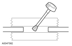
- Hold the terminal in place with an item such as a regular lead pencil at a 90 degree angle from the terminal. (Holding at other than a 90 degree angle may allow the terminal to slip when the solder liquefies.)
- NOTE: The new terminal has pre-applied solder, flux and
temperature-sensitive paint. The paint provides a visual indication when the
terminal has reached the correct temperature to melt solder on the terminal.
When the correct temperature is achieved, the temperature paint will liquefy
and change color.
Place the soldering gun tip on the top of the terminal, but not on the painted areas of the tab. Energize the soldering gun and watch for the painted area of the terminal to liquefy and change color. The paint should liquefy in approximately 25-45 seconds after heating. As soon as the paint color completely changes on either side of the terminal, de-energize the soldering gun and continue to hold the terminal in place with the soldering gun and pencil for an additional 30 seconds.
- Remove the soldering gun and pencil from the terminal. The terminal should be allowed to cool for another 2 minutes before the wiring lead is attached to the terminal.
- Attach the electrical lead connection to this terminal, turn on the heated rear window and verify the operation.
Window Motor Initialization
NOTE: Initialization is required to learn both the full UP and full DOWN positions and the profile of the glass as it travels through the glass channel. Once initialized, obstacle detection is enabled. This procedure is required for LH/RH front (SHO, Limited) or LH front (SE, SEL) window motors.
NOTE: A new (original factory setting) or de-initialized window motor will not operate in one-touch up mode until initialized. If a new window motor has been installed, proceed to the initialization procedure.
NOTE: The window motors must be initialized whenever: a new window regulator and motor is installed, a new window glass is installed, a glass top run removal and installation or when carrying out any operation in which grease or lubricants are applied to the window system.
NOTE: If diagnosing a window switch concern, carry out the window initialization procedure before installing a new window switch.
NOTE: All window components (window glass, window regulator, window motor, seals and glass top run) must be installed and tightened to specification before carrying out the initialization procedure.
De-initialization procedure
NOTE: The window motor must be reset to its original factory settings first, then carry out the following de-initialization procedure.
- Turn the ignition key ON.
- Operate the window control switch in one-touch mode and remove power
from the window motor while the window is moving by one of the
following methods:
- Disconnect the vehicle battery cable while the window is moving.
- Disconnect the window motor connector while the window is moving.
- Remove the window motor fuse while the window is moving.
- This will de-initialize the window motor and reset the window motor to its original factory settings.
- Re-connect the battery cable, window motor connector or re-install the window motor fuse and carry out the initialization procedure to turn the one-touch up feature on.
Initialization procedure
WARNING: Keep objects and body parts clear of the glass panel when carrying out the initialization procedure. During the initialization procedure, the glass panel closes with high force and cannot detect objects in its path. Failure to follow this instruction may result in serious personal injury.
NOTE: The window must be in the full OPEN position for this procedure to operate correctly.
NOTE: If the initialization procedure is only partially completed, the window motor will remain de-initialized and will not operate in one-touch up mode.
- Turn the ignition key ON.
- Activate and hold the window control switch in the UP position at the second detent until the window glass stalls for 2 seconds into the glass top run and release the switch.
- Activate and hold the window control switch in the DOWN position at the second detent until the window glass stalls for 2 seconds at the bottom of its travel and release the switch.
- Test for correct window operation by carrying out the one-touch up and one-touch down features.
Glass Reseal - Windshield
Material
- Position aside the front portion of the LH and RH roof ditch mouldings.
- Remove the scrivet from the front of the roof ditch moulding.
- Pull upward to release the front clips on the roof ditch moulding.
- Position aside the front portion of the roof ditch moulding.
- Remove the upper cowl panel grille. For additional information, refer to Section 501-02.
- Remove the LH and RH A-pillar trim panels. For additional information, refer to Section 501-05.
- Remove the overhead console. For additional information, refer to Section 501-12.
- If equipped with rain sensitive wipers, remove the rain sensor. For additional information, refer to Section 501-16.
- Remove the passenger front assist handle.
- Remove the LH and RH sun visors.
- Lower the front portion of the headliner and block with a suitable material.
- Clean the interior and exterior of the windshield glass surface with glass cleaner.
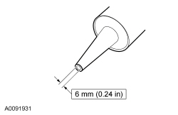
- Cut the urethane adhesive applicator tip to 6 mm (0.24 in).

- NOTE: Use either a high-ratio, electric or battery-operated caulk
gun that will apply the urethane adhesive with less effort and a continuous
bead.
NOTE: Make sure that all gaps in the urethane adhesive are smoothed into one continuous bead.
Apply urethane adhesive over top of the existing urethane adhesive.- Apply the urethane adhesive to the top and sides of the windshield from the interior of the vehicle.
- Apply the urethane adhesive to the bottom of the windshield from the exterior of the vehicle.
- NOTICE: The urethane adhesive must cure for a minimum of one
hour before testing for air or water leaks to make sure of correct adhesion.
After the urethane adhesive has cured, check the windshield seal for air or water leaks through the urethane adhesive bead and add urethane adhesive as necessary.
- Position the front portion of the headliner.
- Install the LH and RH sun visors.
- Install the passenger front assist handle.
- If equipped with rain sensitive wipers, install the rain sensor. For additional information, refer to Section 501-16.
- Install the overhead console. For additional information, refer to Section 501-12.
- Install the LH and RH A-pillar trim panels. For additional information, refer to Section 501-05.
- Install the upper cowl panel grille. For additional information, refer to Section 501-02.
- Reposition the LH and RH roof ditch mouldings and install the scrivet.
- Clean the interior and exterior windshield glass with glass cleaner.
Glass Reseal - Rear
Material
- Remove the rear parcel shelf and rear assist handles. For additional information, refer to Section 501-05.
- Pull down on the back of the headliner to release the hidden fasteners from the body. Refer to the Headliner exploded view in Section 501-05 for fastener location.
- Disconnect the 2 rear window defrost electrical connectors.
- Clean the interior and exterior of the rear window glass surface with glass cleaner.
- Cut the urethane adhesive applicator tip to 6 mm (0.24 in).
- NOTE: Use either a high-ratio, electric or battery-operated caulk gun
that will apply the urethane adhesive with less effort and a continuous
bead.
NOTE: Make sure that all gaps in the urethane adhesive are smoothed into one continuous bead.
Apply urethane adhesive over top of the existing urethane adhesive.- Apply the urethane adhesive to the top, sides and bottom of the rear window glass from the interior of the vehicle.
- NOTICE: The urethane adhesive must cure for a minimum of one
hour before testing for air or water leaks to make sure of correct adhesion.
After the urethane adhesive has cured, check the rear window glass seal for air or water leaks through the urethane adhesive bead and add urethane adhesive as necessary.
- Connect the 2 rear window defrost electrical connectors.
- Install the headliner, parcel shelf and rear assist handles. For additional information, refer to Section 501-05.
- Clean the interior and exterior windshield glass with glass cleaner.
 Diagnosis and Testing
Glass, Frames and Mechanisms
Special Tool(s)
DTC Charts
Diagnostics in this manual assume a certain skill level and knowledge of
Ford-specific diagnostic practices. Refer to Diagnostic Methods in&nb ...
 Removal and Installation
Glass, Frames and Mechanisms - Exploded View, Front Door
For additional information, refer to the procedures in this section.
Window Glass - Front Door
Removal and Installation
NOTE: The pow ...
Other materials:
Mobile communications equipment
Using mobile communications equipment is becoming increasingly
important in the conduct of business and personal affairs. However, you
must not compromise your own or othersŌĆÖ safety when using such
equipment. Mobile communications can enhance personal safety and
security when appropriately use ...
Specifications, Description and Operation
SPECIFICATIONS
Material
Torque Specifications
DESCRIPTION AND OPERATION
Glass, Frames and Mechanisms
Overview
The accessory delay relay, located in the BCM, provides voltage for the
operation of the power windows and the roof opening panel (if equipped). Refer
to Delayed Accessory Power.
St ...
Specifications, Description and Operation
SPECIFICATIONS
Torque Specifications
DESCRIPTION AND OPERATION
Rear View Mirrors
Exterior, Power
Overview
Power mirrors allow the LH and RH exterior mirror glass to be positioned
electronically. The position of the power mirror glass is controlled by the
exterior mirror control switch. Selecting ...
