Glass, Frames and Mechanisms
Special Tool(s)
DTC Charts
Diagnostics in this manual assume a certain skill level and knowledge of Ford-specific diagnostic practices. Refer to Diagnostic Methods in Section 100-00 for information about these practices.
BCM DTC Chart
HVAC Module DTC Chart

Symptom Chart
Diagnostics in this manual assume a certain skill level and knowledge of Ford-specific diagnostic practices. Refer to Diagnostic Methods in Section 100-00 for information about these practices.
Pinpoint Tests
Pinpoint Test A: All Power Windows are Inoperative
Diagnostic Overview
Diagnostics in this manual assume a certain skill level and knowledge of Ford-specific diagnostic practices. Refer to Diagnostic Methods in Section 100-00 for information about these practices.
Refer to Wiring Diagrams Cell 100, Power Windows for schematic and connector information.
Normal Operation and Fault Conditions
The accessory delay relay, located at the BCM, provides the voltage for all power window operation. The accessory delay relay is controlled by the BCM. Refer to Delayed Accessory Power in Glass, Frames and Mechanisms.
-
Possible Sources:
- Fuse
- Accessory delay relay
- Wiring, terminals or connectors
- BCM
Visual Inspection and Diagnostic Pre-checks
Visually inspect the accessory delay relay.
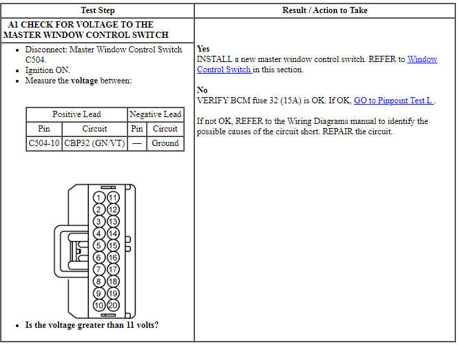
Verify BCM fuse 32 (15A) is OK.
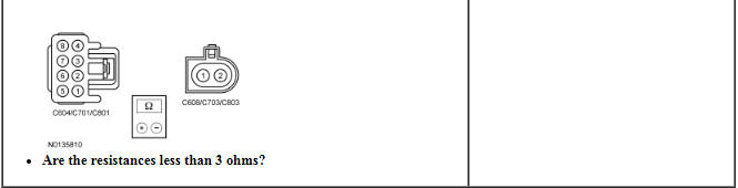
PINPOINT TEST A: ALL POWER WINDOWS ARE INOPERATIVE
NOTICE: Use the correct probe adapter(s) from the Flex Probe Kit when making measurements. Failure to use the correct probe adapter(s) may damage the connector.
Pinpoint Test B: All Rear Passenger Power Windows are Inoperative
Diagnostic Overview
Diagnostics in this manual assume a certain skill level and knowledge of Ford-specific diagnostic practices. Refer to Diagnostic Methods in Section 100-00 for information about these practices.
Refer to Wiring Diagrams Cell 100, Power Windows for schematic and connector information.
Normal Operation and Fault Conditions
When the master window control lock-out switch is in the UNLOCK position, voltage is supplied to the LH rear and RH rear window control switches. The LH and RH rear window control switches share a high current voltage circuit from the BCM.
For police vehicles only, there is an in-line connector which, if disconnected, will disable LH and RH rear window operation except from the master window control switch (regardless of the lock-out switch position).
-
Possible Sources:
- Circuit breaker
- Wiring, terminals or connectors
- Master window control switch
- In-line connector disconnected (police vehicles only)
Visual Inspection and Diagnostic Pre-checks
Make sure the master window control lock-out switch is in the UNLOCK position.
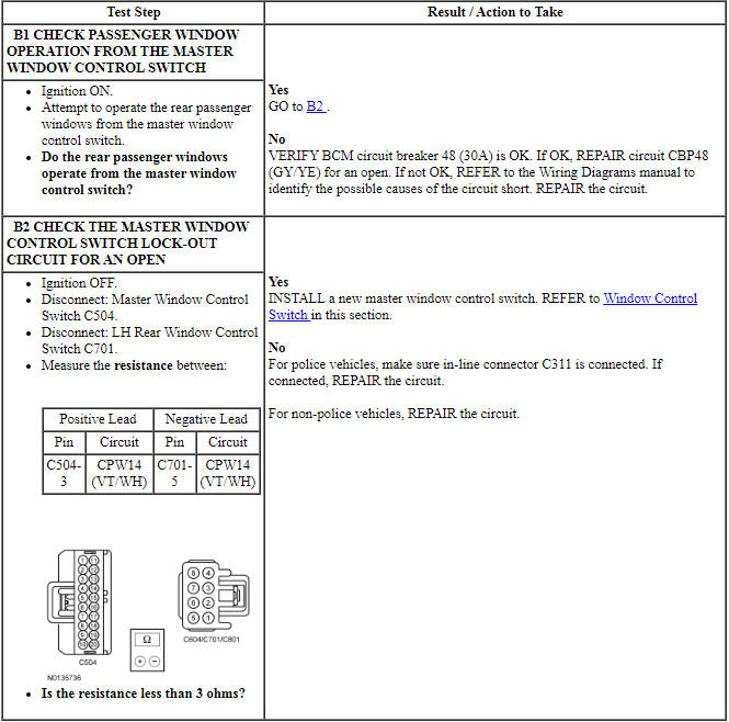
PINPOINT TEST B: ALL REAR PASSENGER POWER WINDOWS ARE INOPERATIVE
NOTICE: Use the correct probe adapter(s) from the Flex Probe Kit when making measurements. Failure to use the correct probe adapter(s) may damage the connector.
Pinpoint Test C: A Single Power Window is Inoperative - LH Front
Diagnostic Overview
Diagnostics in this manual assume a certain skill level and knowledge of Ford-specific diagnostic practices. Refer to Diagnostic Methods in Section 100-00 for information about these practices.
Refer to Wiring Diagrams Cell 100, Power Windows for schematic and connector information.
Normal Operation and Fault Conditions
The window control switch sends 2 separate signals to the window motor: up and down. When the window control switch is pressed to the first detent position, a 12-volt signal is sent to the window motor to request an up or down operation. When auto up or auto down is requested (switch pressed to the second detent position), the window control switch provides a 12-volt signal on both the up and down line simultaneously. During an auto up or auto down request, the window motor determines intended window direction by the signal first received. If the window control switch is pressed too quickly to the second detent position (less than 5 ms of time between first detent signal and second detent signal), the window motor is unable to determine the intended direction request and will not operate until the window control switch is released and pressed again. The up and down feeds to the window motor are all low current. The high current required to operate the front window is supplied through a dedicated power and ground circuit to the motor.
-
Possible Sources:
- Fuse
- Wiring, terminals or connectors
- Master window control switch
- LH front window regulator motor
Visual Inspection and Diagnostic Pre-checks
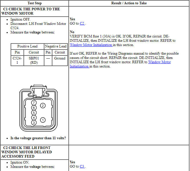
Verify BCM fuse 1 (30A) is OK.
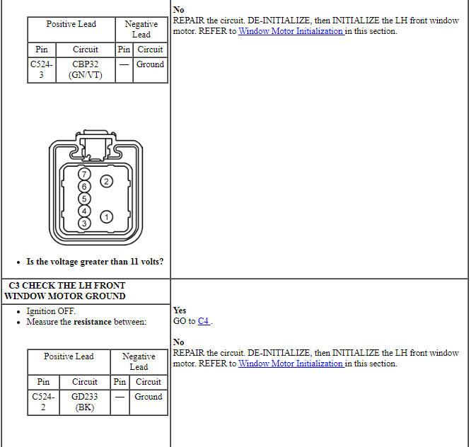
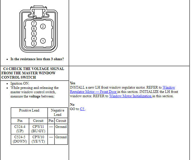
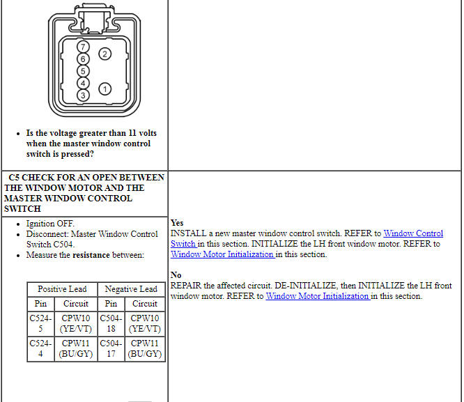
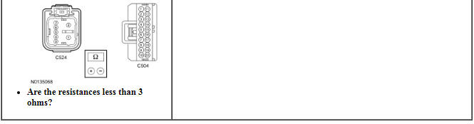
PINPOINT TEST C: A SINGLE POWER WINDOW IS INOPERATIVE - LH FRONT
NOTICE: Use the correct probe adapter(s) from the Flex Probe Kit when making measurements. Failure to use the correct probe adapter(s) may damage the connector.
Pinpoint Test D: A Single Power Window is Inoperative - RH Front, SHO, Limited
Diagnostic Overview
Diagnostics in this manual assume a certain skill level and knowledge of Ford-specific diagnostic practices. Refer to Diagnostic Methods in Section 100-00 for information about these practices.
Refer to Wiring Diagrams Cell 100, Power Windows for schematic and connector information.
Normal Operation and Fault Conditions
The window control switch sends 2 separate signals to the window motor: up and down. When the window control switch is pressed to the first detent position, a 12-volt signal is sent to the window motor to request an up or down operation. When auto up or auto down is requested (switch pressed to the second detent position), the window control switch provides a 12-volt signal on both the up and down line simultaneously. During an auto up or auto down request, the window motor determines intended window direction by the signal first received. If the window control switch is pressed too quickly to the second detent position (less than 5 ms of time between first detent signal and second detent signal), the window motor is unable to determine the intended direction request and will not operate until the window control switch is released and pressed again. The up and down feeds to the window motor are all low current. The high current required to operate the front window is supplied through a dedicated power and ground circuit to the motor.
-
Possible Sources:
- Fuse
- Wiring, terminals or connectors
- Master window control switch
- RH front window control switch
- RH front window regulator motor
Visual Inspection and Diagnostic Pre-checks
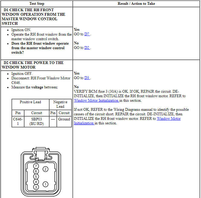
Verify BCM fuse 3 (30A) is OK.
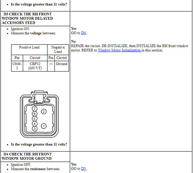
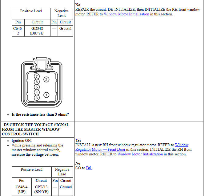
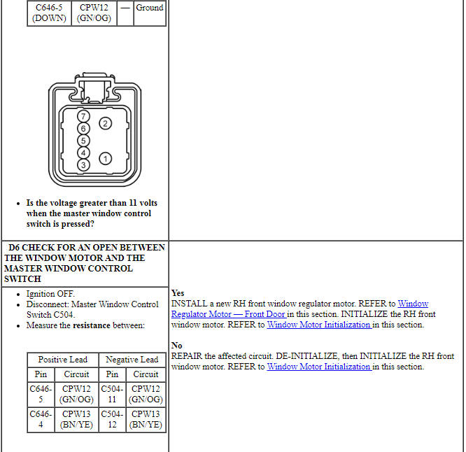
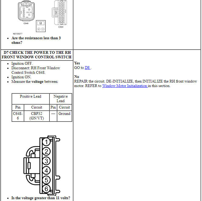
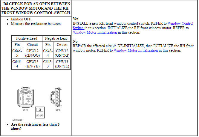
PINPOINT TEST D: A SINGLE POWER WINDOW IS INOPERATIVE - RH FRONT, SHO, LIMITED
NOTICE: Use the correct probe adapter(s) from the Flex Probe Kit when making measurements. Failure to use the correct probe adapter(s) may damage the connector.
Pinpoint Test E: A Single Power Window is Inoperative - RH Front, SE, SEL
Diagnostic Overview
Diagnostics in this manual assume a certain skill level and knowledge of Ford-specific diagnostic practices. Refer to Diagnostic Methods in Section 100-00 for information about these practices.
Refer to Wiring Diagrams Cell 100, Power Windows for schematic and connector information.
Normal Operation and Fault Conditions
Refer to Passenger Window Control Switch - Front in Glass, Frames and Mechanisms for window control switch information. The RH front window motor is bi-directional. Window direction is determined by the polarity of the voltage and ground being supplied to the motor from the window control switch(es).
-
Possible Sources:
- Wiring, terminals or connectors
- Master window control switch
- RH front window control switch
- RH front window motor
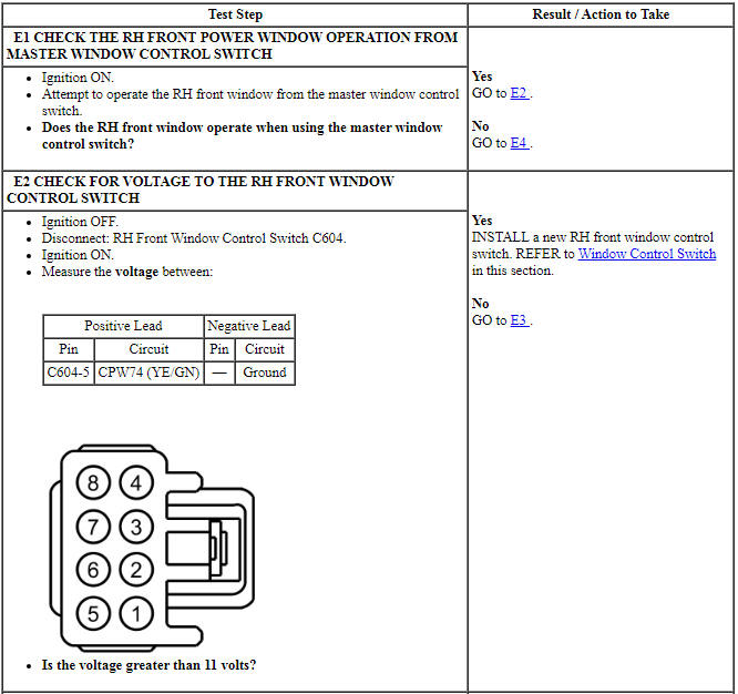
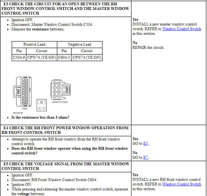
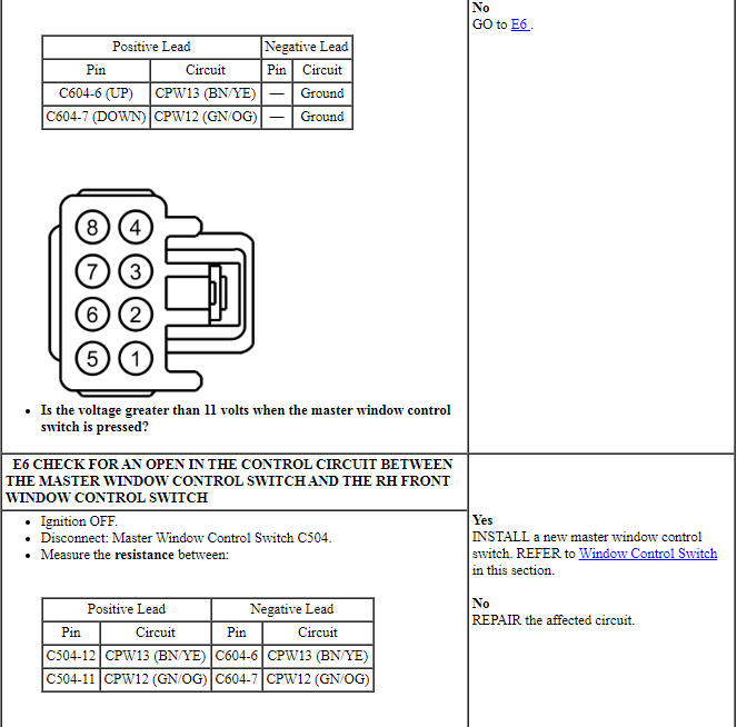
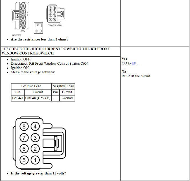
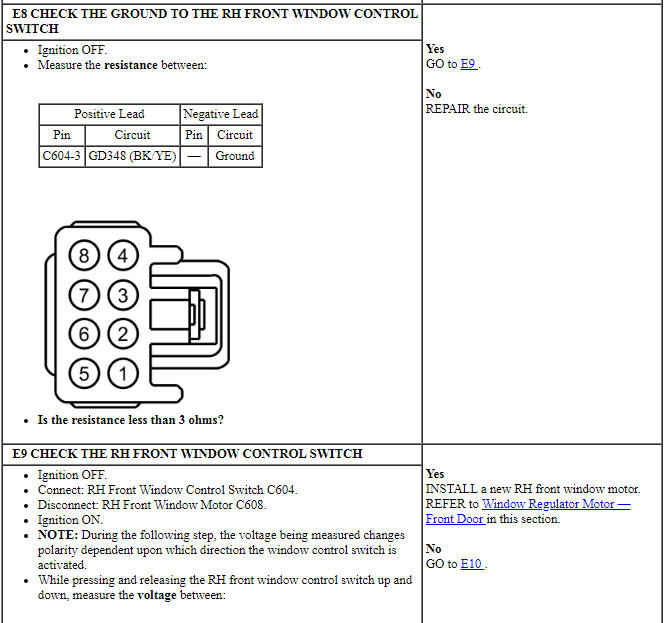
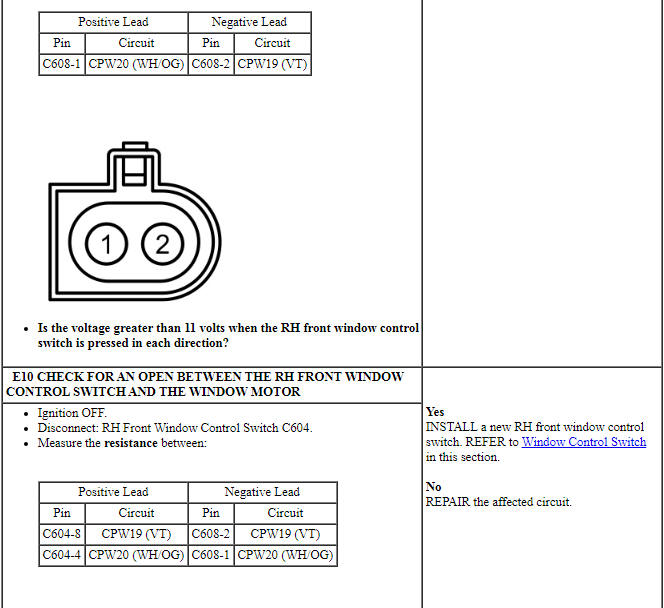
PINPOINT TEST E: A SINGLE POWER WINDOW IS INOPERATIVE - RH FRONT, SE, SEL
NOTICE: Use the correct probe adapter(s) from the Flex Probe Kit when making measurements. Failure to use the correct probe adapter(s) may damage the connector.
Pinpoint Test F: A Single Power Window is Inoperative - LH Rear
Diagnostic Overview
Diagnostics in this manual assume a certain skill level and knowledge of Ford-specific diagnostic practices. Refer to Diagnostic Methods in Section 100-00 for information about these practices.
Refer to Wiring Diagrams Cell 100, Power Windows for schematic and connector information.
Normal Operation and Fault Conditions
Refer to Passenger Window Control Switch - Rear in Glass, Frames and Mechanisms for window control switch information. The LH rear window motor is bi-directional. Window direction is determined by the polarity of the voltage and ground being supplied to the motor from the window control switch(es).
-
Possible Sources:
- Wiring, terminals or connectors
- Master window control switch
- LH rear window control switch
- LH rear window motor
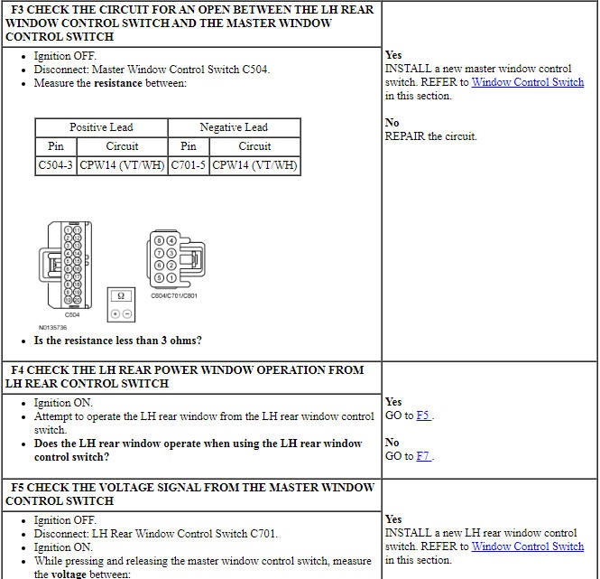
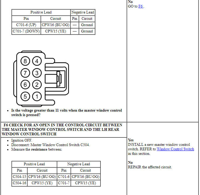
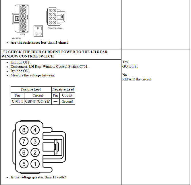
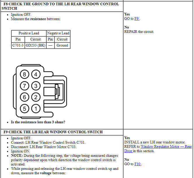
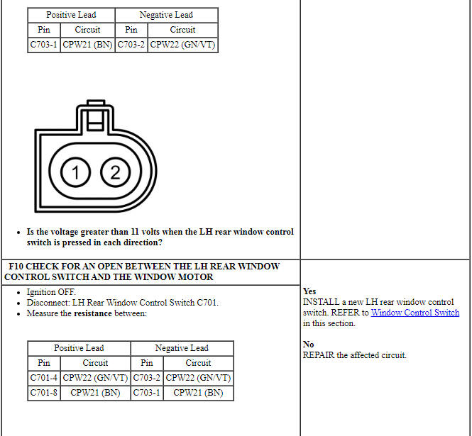
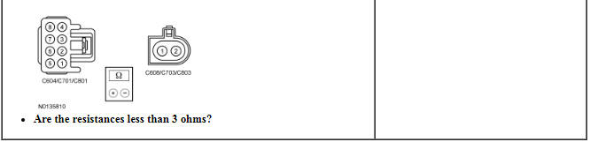
PINPOINT TEST F: A SINGLE POWER WINDOW IS INOPERATIVE - LH REAR
NOTICE: Use the correct probe adapter(s) from the Flex Probe Kit when making measurements. Failure to use the correct probe adapter(s) may damage the connector.

Pinpoint Test G: A Single Power Window is Inoperative - RH Rear
Diagnostic Overview
Diagnostics in this manual assume a certain skill level and knowledge of Ford-specific diagnostic practices. Refer to Diagnostic Methods in Section 100-00 for information about these practices.
Refer to Wiring Diagrams Cell 100, Power Windows for schematic and connector information.
Normal Operation and Fault Conditions
Refer to Passenger Window Control Switch - Rear in Glass, Frames and Mechanisms for window control switch information. The RH rear window motor is bi-directional. Window direction is determined by the polarity of the voltage and ground being supplied to the motor from the window control switch(es).
-
Possible Sources:
- Wiring, terminals or connectors
- Master window control switch
- RH rear window control switch
- RH rear window motor
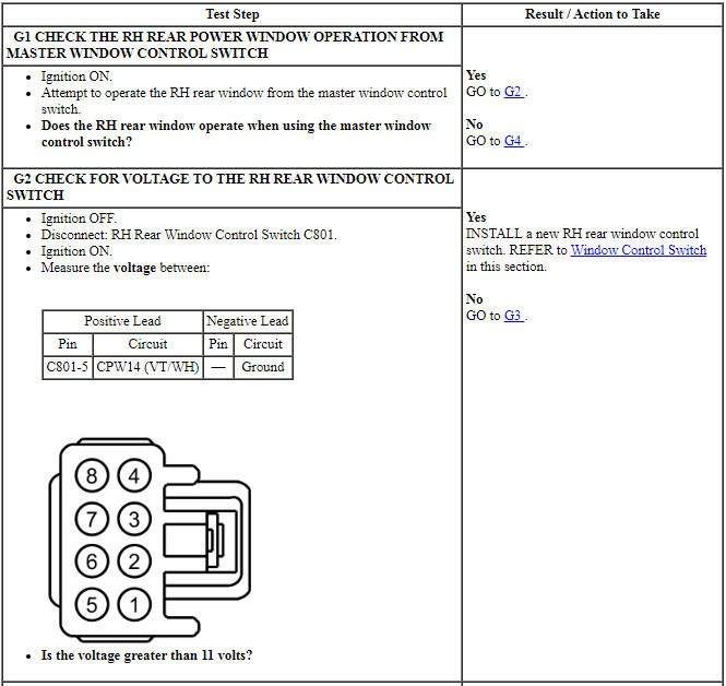
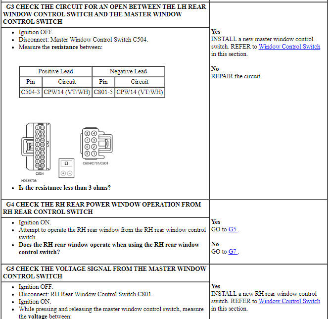
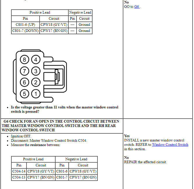
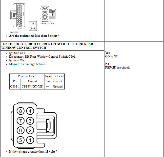
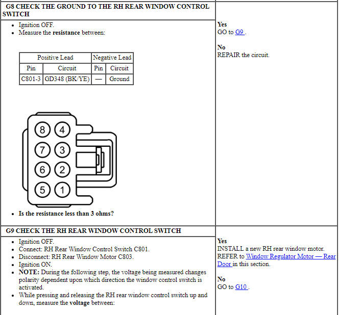
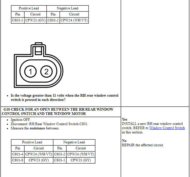
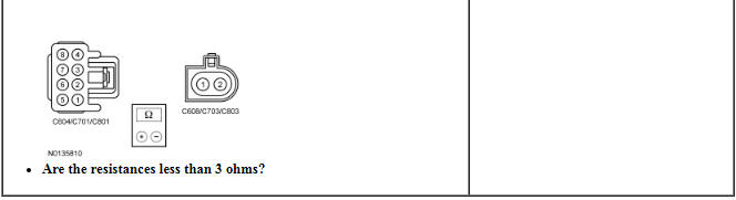
PINPOINT TEST G: A SINGLE POWER WINDOW IS INOPERATIVE - RH REAR
NOTICE: Use the correct probe adapter(s) from the Flex Probe Kit when making measurements. Failure to use the correct probe adapter(s) may damage the connector.
Pinpoint Test H: The One-Touch Up/Down Feature is Inoperative
Diagnostic Overview
Diagnostics in this manual assume a certain skill level and knowledge of Ford-specific diagnostic practices. Refer to Diagnostic Methods in Section 100-00 for information about these practices.
Refer to Wiring Diagrams Cell 100, Power Windows for schematic and connector information.
NOTE: For SHO or Limited only, the one-touch up/down feature is available on both the LH and RH front windows. For SE and SEL, the one-touch up/down feature is only available on the LH front window.
Normal Operation and Fault Conditions
The window control switch sends 2 separate signals to the window motor: up and down. When the window control switch is pressed to the first detent position, a 12-volt signal is sent to the window motor to request an up or down operation. When auto up or auto down is requested (switch pressed to the second detent position), the window control switch provides a 12-volt signal on both the up and down line simultaneously. During an auto up or auto down request, the window motor determines intended window direction by the signal first received. If the window control switch is pressed too quickly to the second detent position (less than 5 ms of time between first detent signal and second detent signal), the window motor is unable to determine the intended direction request and will not operate until the window control switch is released and pressed again. The up and down feeds to the window motor are all low current. The high current required to operate the front window is supplied through a dedicated power and ground circuit to the motor.
-
Possible Sources:
- Power window regulator motor not initialized
- Window control switch
- Window regulator motor
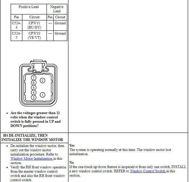
PINPOINT TEST H: THE ONE-TOUCH UP/DOWN FEATURE IS INOPERATIVE
NOTICE: Use the correct probe adapter(s) from the Flex Probe Kit when making measurements. Failure to use the correct probe adapter(s) may damage the connector.
Pinpoint Test I: The Global Open Function is Inoperative - SHO, Limited
Diagnostic Overview
Diagnostics in this manual assume a certain skill level and knowledge of Ford-specific diagnostic practices. Refer to Diagnostic Methods in Section 100-00 for information about these practices.
Refer to Wiring Diagrams Cell 100, Power Windows for schematic and connector information.
Normal Operation and Fault Conditions
When the BCM receives the correct input from the Remote Keyless Entry (RKE), the BCM will send a signal to operate the roof opening panel motor to the VENT position (if equipped) and activate a one-touch down operation of both front door windows. The global open/close feature does not operate if the accessory delay relay is active.
DTC Fault Trigger Conditions
-
Possible Sources:
- Window regulator motor not initialized
- Fuse
- Wiring, terminals or connections
- Window regulator motor
- Roof opening panel motor/module (if equipped)
- RKE transmitter
- BCM
Visual Inspection and Diagnostic Pre-checks
One-touch up/down must be activated from the message center for the global open function to operate correctly. Make sure one-touch up/down is activated before proceeding with this diagnostic.
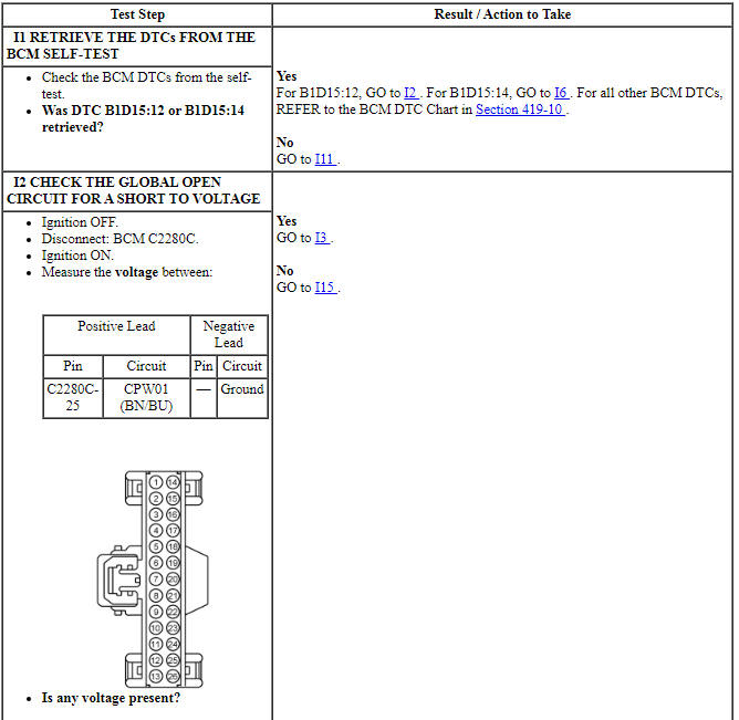
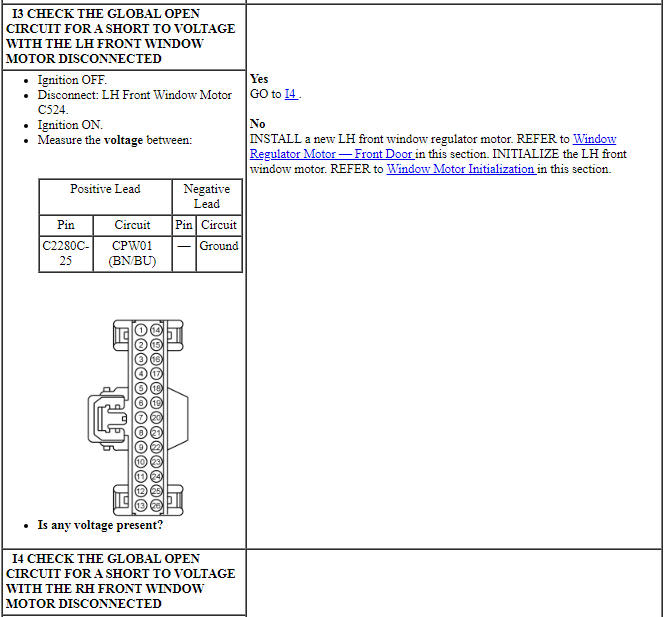
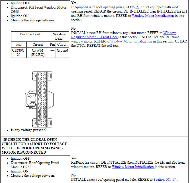
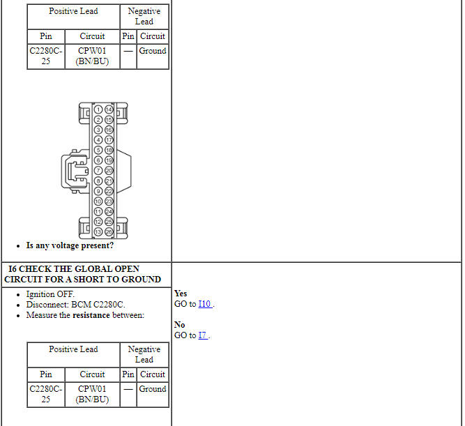
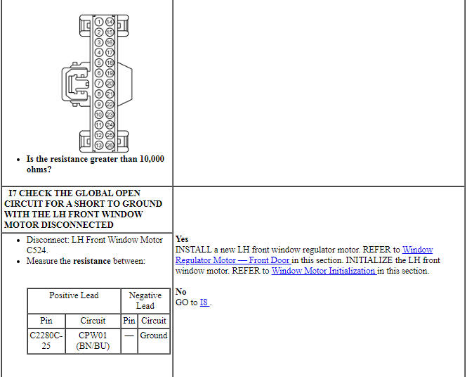
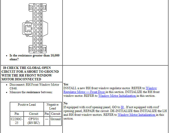
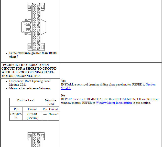
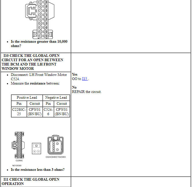
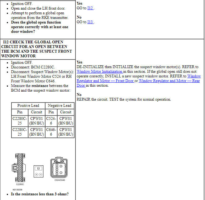
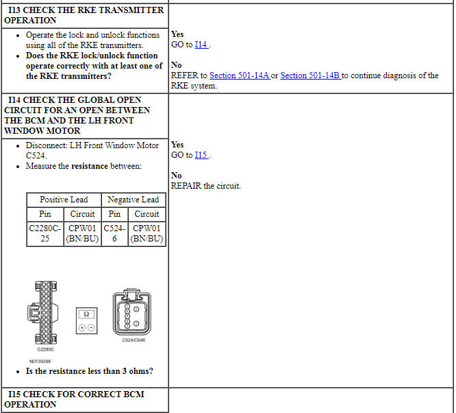
PINPOINT TEST I: THE GLOBAL OPEN FUNCTION IS INOPERATIVE - SHO, LIMITED
NOTICE: Use the correct probe adapter(s) from the Flex Probe Kit when making measurements. Failure to use the correct probe adapter(s) may damage the connector.
Pinpoint Test J: The Defrost System is Inoperative
Diagnostic Overview
Diagnostics in this manual assume a certain skill level and knowledge of Ford-specific diagnostic practices. Refer to Diagnostic Methods in Section 100-00 for information about these practices.
Refer to Wiring Diagrams Cell 56, Heated Window for schematic and connector information.
Normal Operation and Fault Conditions
For a complete description of normal operation, refer to Rear Window Defrost in Glass, Frames and Mechanisms.
DTC Fault Trigger Conditions
-
Possible Sources:
- Fuse(s)
- Rear window defrost relay (located on the BJB )
- Wiring, terminals or connectors
- Rear window defrost grid
- FCIM
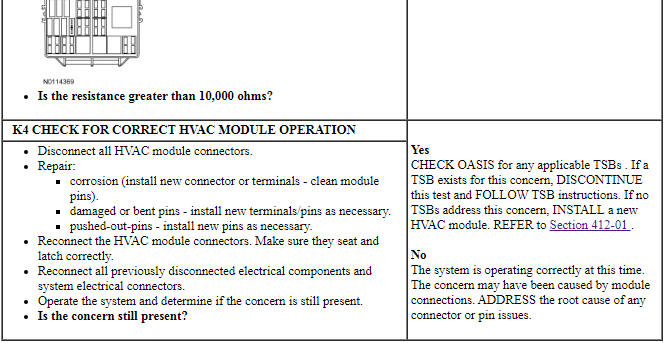
- HVAC module
Visual Inspection and Diagnostic Pre-checks
Verify BJB fuse 26 (40A) and 93 (5A) are OK.
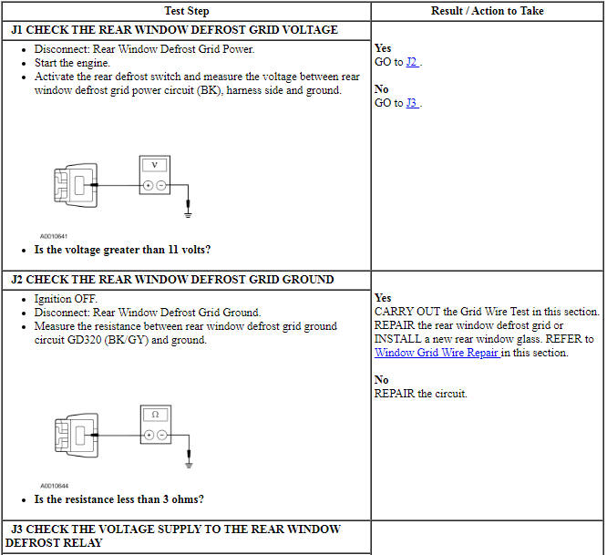
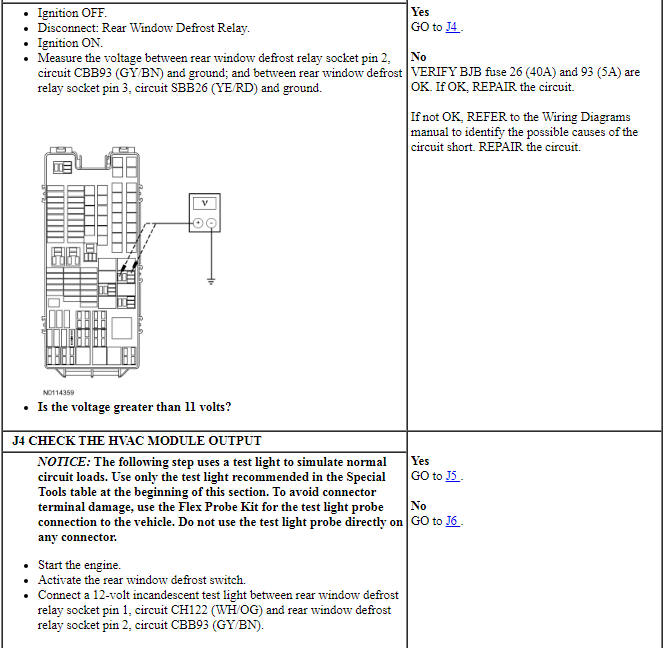
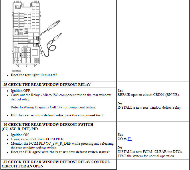
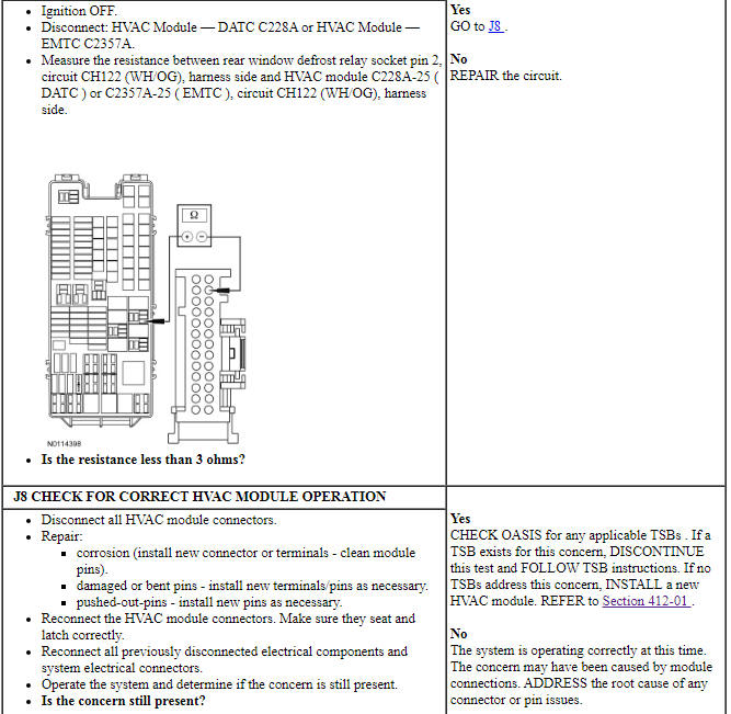
PINPOINT TEST J: THE DEFROST SYSTEM IS INOPERATIVE
NOTICE: Use the correct probe adapter(s) from the Flex Probe Kit when making measurements. Failure to use the correct probe adapter(s) may damage the connector.
Pinpoint Test K: The Defrost System Will Not Shut Off Automatically
Diagnostic Overview
Diagnostics in this manual assume a certain skill level and knowledge of Ford-specific diagnostic practices. Refer to Diagnostic Methods in Section 100-00 for information about these practices.
Refer to Wiring Diagrams Cell 56, Heated Window for schematic and connector information.
Normal Operation and Fault Conditions
For a complete description of normal operation, refer to Rear Window Defrost in Glass, Frames and Mechanisms.
DTC Fault Trigger Conditions

-
Possible Sources:
- Wiring, terminals or connectors
- Rear window defrost relay (located on the BJB )
- HVAC module
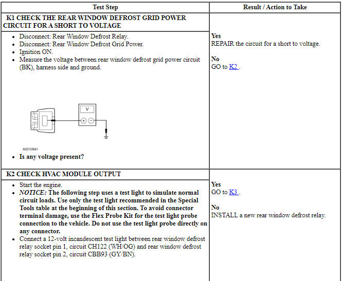
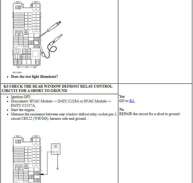
PINPOINT TEST K: THE DEFROST SYSTEM WILL NOT SHUT OFF AUTOMATICALLY
NOTICE: Use the correct probe adapter(s) from the Flex Probe Kit when making measurements. Failure to use the correct probe adapter(s) may damage the connector.
Pinpoint Test L: The Delayed Accessory is Inoperative
Diagnostic Overview
Diagnostics in this manual assume a certain skill level and knowledge of Ford-specific diagnostic practices. Refer to Diagnostic Methods in Section 100-00 for information about these practices.
Refer to Wiring Diagrams Cell 100, Power Windows for schematic and connector information.
Normal Operation and Fault Conditions
For a complete description of normal operation, refer to Delayed Accessory Power in Glass, Frames and Mechanisms.
DTC Fault Trigger Conditions
-
Possible Sources:
- Fuse(s)
- Accessory delay relay (located on the BCM )
- Wiring, terminals or connectors
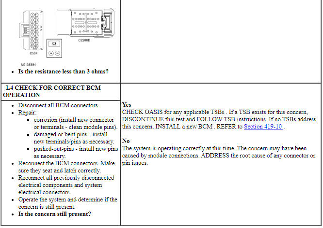
- BCM
Visual Inspection and Diagnostic Pre-checks
Verify BCM fuse 32 (15A) is OK.
PINPOINT TEST L: THE DELAYED ACCESSORY IS INOPERATIVE
NOTICE: Use the correct probe adapter(s) from the Flex Probe Kit when making measurements. Failure to use the correct probe adapter(s) may damage the connector.
Pinpoint Test M: The Delayed Accessory Does Not Turn Off
Diagnostic Overview
Diagnostics in this manual assume a certain skill level and knowledge of Ford-specific diagnostic practices. Refer to Diagnostic Methods in Section 100-00 for information about these practices.
Refer to Wiring Diagrams Cell 100, Power Windows for schematic and connector information.
Normal Operation and Fault Conditions
For a complete description of normal operation, refer to Delayed Accessory Power in Glass, Frames and Mechanisms.
DTC Fault Trigger Conditions

-
Possible Sources:
- Accessory delay relay (located on the BCM )
- Wiring, terminals or connections
- BCM
PINPOINT TEST M: THE DELAYED ACCESSORY DOES NOT TURN OFF
NOTICE: Use the correct probe adapter(s) from the Flex Probe Kit when making measurements. Failure to use the correct probe adapter(s) may damage the connector.
Component Test
Grid Wire Test
- Using a bright lamp in the vehicle, inspect the wire grid from the exterior. A broken grid wire will appear as a brown spot.
- Run the engine at idle. Set the rear window defrost switch to ON. The indicator light should come on.
- Working in the vehicle with a voltmeter, contact the broad red-brown stripes of the rear glass window positive lead to battery side and the negative lead to ground side. The meter should read 10-13 volts. A lower voltage reading indicates a loose ground connection.
- Contact a good ground point with the negative lead of the meter. The voltage reading should not change.
- With the negative lead of the meter grounded, touch each grid line of the heated rear window glass at its midpoint with the positive lead. A reading of approximately 6 volts indicates the line is good. A reading of 0 volt indicates the line is broken between the midpoint and the B+ side of the grid line. A reading of 12 volts indicates the circuit is broken between the midpoint of the grid line and ground.
- Pinpointing the exact position of the break can be accomplished (if the voltmeter reads 0 volt when the midpoint of the grid line is touched with the positive lead of the voltmeter) by moving the positive lead of the voltmeter toward the B+ side of the grid line and touching the grid line until the voltmeter reads 12 volts. If the voltmeter reads 12 volts when the midpoint of the grid line is touched with the positive lead of the voltmeter, simply move the positive lead of the voltmeter toward the ground connection of the grid line and touch the grid line until the voltmeter reads 0 volt.
 Specifications, Description and Operation
SPECIFICATIONS
Material
Torque Specifications
DESCRIPTION AND OPERATION
Glass, Frames and Mechanisms
Overview
The accessory delay relay, located in the BCM, provides voltage for the
operation ...
 General Procedures
Window Grid Wire Repair
General Equipment
Material
NOTE: The grid line material is not embedded into the glass, but is
baked to the glass surface and consequently can be scraped off. An undama ...
Other materials:
Reporting safety defects (Canada only)
This pertains to vehicles delivered to authorized Canadian dealers.
In those cases, where you continue to feel that the efforts by Ford of
Canada and the authorized dealer to resolve a factory-related vehicle
service concern have been unsatisfactory, Ford of Canada participates in
an impartial ...
Fuel System - General Information
SPECIFICATIONS
General Specifications
Torque Specifications
DESCRIPTION AND OPERATION
Fuel System
2.0L Gasoline Turbocharged Direct Injection (GTDI)
The fuel system:
is a variable speed Closed Loop Pressure Control (CLPC) Fuel System with
Gasoline Turbocharged Direct Injection (GTDI).
...
Battery, Mounting and Cables
SPECIFICATIONS
General Specifications
Torque Specifications
DESCRIPTION AND OPERATION
Battery and Cables
Overview
The battery and cable system consists of the following components:
Battery
Battery cable assembly (both negative and positive cable serviced as an
assembly)
High current&nb ...
