Engine
Special Tool(s)
Material
NOTICE: Do not loosen or remove the crankshaft pulley bolt without first installing the special tools as instructed in this procedure. The crankshaft pulley and the crankshaft timing sprocket are not keyed to the crankshaft. The crankshaft, the crankshaft sprocket and the pulley are fitted together by friction, using diamond washers between the flange faces on each part. For that reason, the crankshaft sprocket is also unfastened if the pulley bolt is loosened. Before any repair requiring loosening or removal of the crankshaft pulley bolt, the crankshaft and camshafts must be locked in place by the special service tools, otherwise severe engine damage can occur.
NOTICE: During engine repair procedures, cleanliness is extremely important. Any foreign material, including any material created while cleaning gasket surfaces that enters the oil passages, coolant passages or the oil pan, can cause engine failure.
NOTE: For additional information, refer to the exploded view under the Assembly procedure in this section.
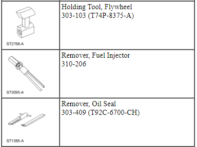
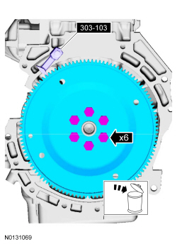
- NOTE: Do not reuse the flexplate bolts.
Install the Flywheel Holding Tool and remove the 6 bolts and the flexplate.
- Discard the bolts.
- Mount the engine on a suitable Engine Stand.
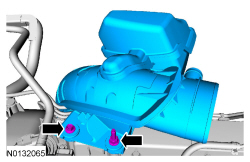
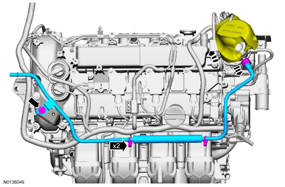
- Loosen the turbocharger outlet tube clamp.
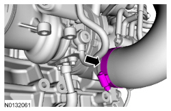
- Remove the 2 bolts and the turbocharger outlet tube.
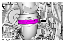
- Loosen the turbocharger inlet tube clamp.
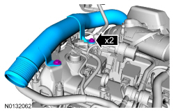
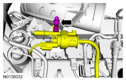
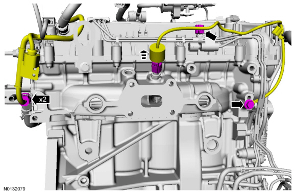
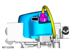
- Remove the engine appearance cover mounting stud and position the EVAP canister purge valve aside.
- Detach the 2 wiring harness retainers.
- Remove the nut and the ground strap.
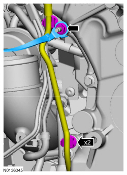
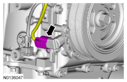
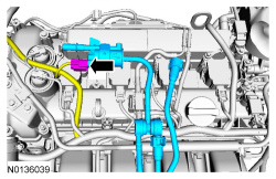
- Disconnect the CKP sensor electrical connector.
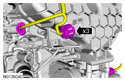
- Remove the bolt, stud bolt and the turbocharger inlet tube.
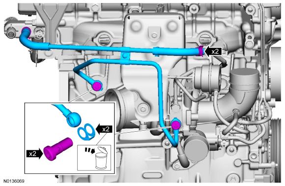
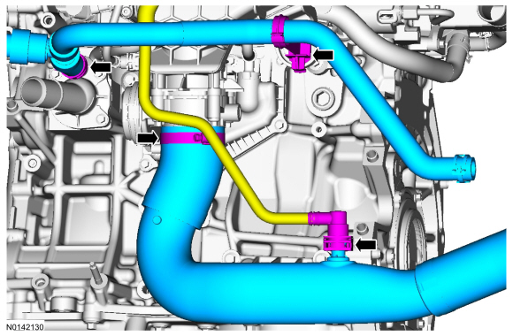
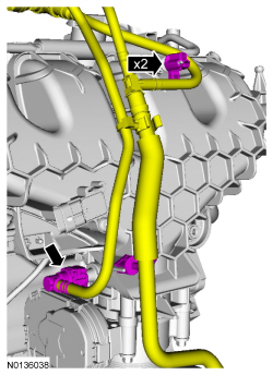
- Remove the 2 turbocharger coolant tube banjo bolts and discard the
gaskets.
- Loosen the 2 clamps and remove the turbocharger coolant tube.
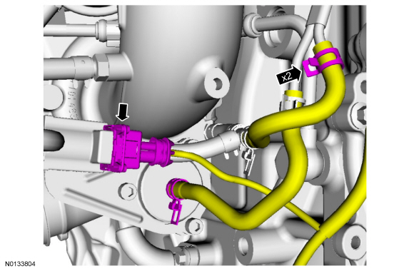
- NOTE: Early build engine with metal vacuum tubes shown, late
build engines with nylon vacuum tubes similar.
Disconnect the 2 turbocharger control vacuum hoses and the electrical connector.
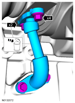
- NOTE: Do not reuse the turbocharger oil supply tube/gaskets, new
parts must be installed.
Remove the 2 banjo bolts and the turbocharger oil supply tube.
- Discard the turbocharger oil supply tube and gaskets.
- Remove and discard the turbocharger oil filter.
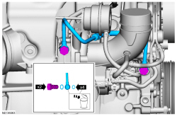
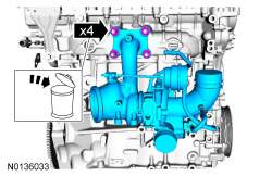
- NOTE: Do not reuse the turbocharger oil return tube/gaskets, new
parts must be installed.
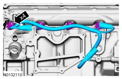
Remove the 4 bolts and the turbocharger oil return tube.
- Discard the turbocharger oil return tube and gaskets.
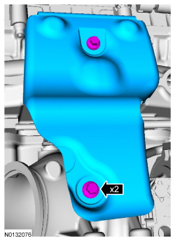
- Remove the 2 bolts and the turbocharger heat shield.
- Remove the 4 nuts and the turbocharger.
- Discard the nuts.
- Remove and discard the turbocharger gasket and the 4 turbocharger-to-cylinder head studs.
- Slide the insulator up and disconnect the CHT sensor electrical
connector.
- Detach the wiring harness retainer.
- Disconnect the ECT sensor electrical connector.
- Remove the bolt and the ground wire.
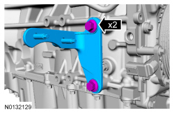
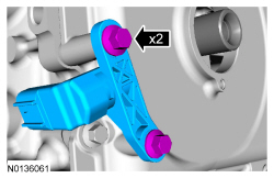
- Remove the 2 bolts and the RH halfshaft bracket.
- Loosen the 3 coolant pump pulley bolts.
- Remove the accessory drive belt.
- Remove the 3 bolts and the accessory drive belt tensioner.
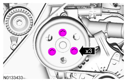
- Remove the 3 bolts and the coolant pump pulley.
- Remove the stud bolt, the 2 bolts and the generator.
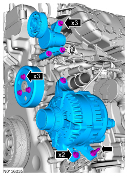
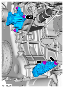
- Remove the 3 bolts and the coolant pump.
- Remove the bolt, the nut and the A/C compressor bracket.
- Disconnect the EVAP tube quick connect coupling. For additional
information, refer to the quick connect coupling procedure in Section
310-00.
- Detach the heater hose retainer from the intake manifold.
- Loosen the clamp and remove the heater hose.
- Loosen the clamp and remove the CAC outlet tube.
- Disconnect the EOP switch electrical connector.
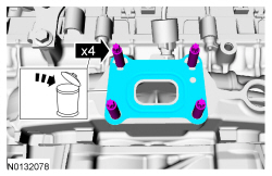
- Remove the 4 bolts and the oil filter adapter.
- Discard the gasket.
- Disconnect the EVAP tube quick connect coupling. For additional
information, refer to the quick connect coupling procedure in Section
310-00.
- Detach the 2 EVAP tube retainers.
- Disconnect the EVAP canister purge valve electrical connector.
- Remove the EVAP canister purge valve and tube assembly.
- Disconnect the fuel supply tube from the fuel injection pump. For
additional information, refer to the quick connect coupling procedure
in Section 310-00.
- Detach the 2 fuel tube retainers from the intake manifold.
- Remove the bolt and the fuel jumper tube.
- Disconnect the MAP sensor, the FRP sensor and fuel charge harness electrical connectors.
- Disconnect the 2 brake vacuum tube quick connect couplings. For additional information, refer to Section 310-00.
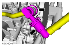
- Depress the quick release locking ring and pull the brake vacuum tube
out of the intake manifold quick connect fitting.
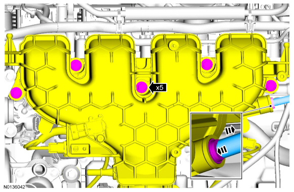
- Remove the 5 intake manifold bolts and position the intake manifold aside.
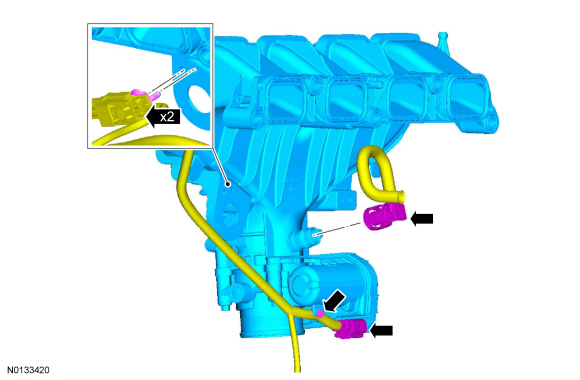
- Disconnect the TB electrical connector and detach the wiring harness
retainer from the TB.
- Detach the 2 KS wiring harness retainers from the intake manifold.
- Disconnect the PCV hose and remove the intake manifold.
- Disconnect the 2 KS electrical connectors.
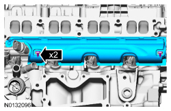
- Remove the 2 bolts and the 2 KS.
- Detach the 2 wiring harness retainers.
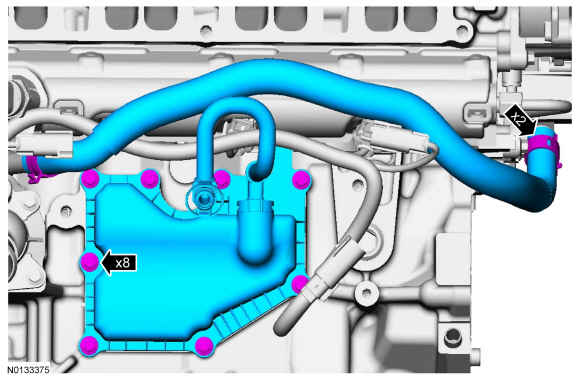
- Remove the 8 bolts and the crankcase vent oil separator.
- Loosen the 2 clamps and remove the coolant bypass hose.
- Disconnect the 4 fuel injector electrical connectors and remove the fuel charge wiring harness.
- Remove the 2 pin-type retainers and the fuel rail insulator.
- Disconnect the fuel injection pump electrical connector.
- Remove the fuel injection pump insulator.
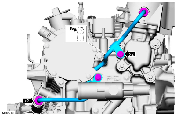
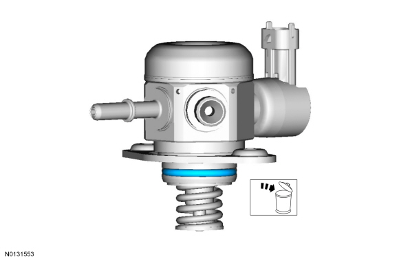
- NOTE: To release the fuel pressure in the high pressure fuel
tube, wrap the fuel injection pump flare nut with a shop towel to absorb any
residual fuel pressure during the loosening of the fuel injection pump flare
nut.
Loosen the 2 high pressure fuel tube flare nuts.
- Remove the 2 bolts and the high pressure fuel tube.
- Discard the high pressure fuel tube.
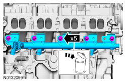
- NOTE: Use compressed air and remove any dirt or foreign material
from the cylinder head, block and general surrounding area of the fuel rail
and injectors.
NOTE: When removing the fuel rails, the fuel injectors may remain in the fuel rails but normally remain in the cylinder head and require the use of a Fuel Injector Remover tool to extract.
Remove the 5 bolts and the fuel rail.- Discard the bolts.
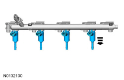
- Remove any of the fuel injectors that remained in the fuel rail.
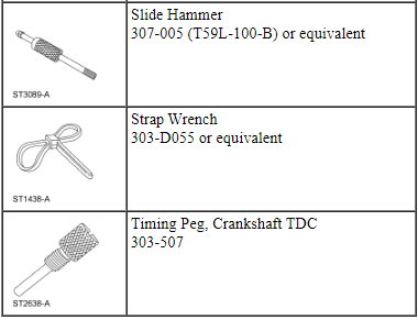
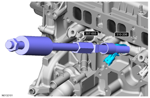
- Using the Slide Hammer and the Fuel Injector Remover, remove the fuel injectors that remained in the cylinder head.
- Remove and discard the fuel injector clips.
- Discard the upper fuel injector O-ring seals and the upper fuel injector O-ring seal support rings.
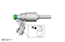
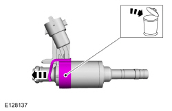
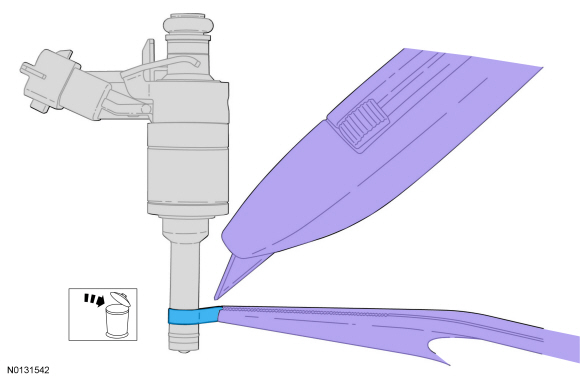
- NOTICE: Do not attempt to cut the lower Teflon seal without
first pulling it away from the fuel injector or damage to the injector may
occur.
NOTE: Be very careful when removing the lower Teflon seals, not to scratch, nick or gouge the fuel injectors.
Pull the lower Teflon seal away from the injector with narrow tip pliers.
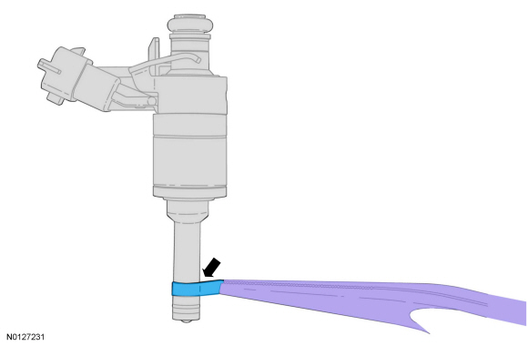
- Carefully cut and discard the lower fuel injector Teflon seals.
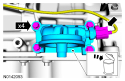
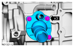
- Remove the 3 bolts and the thermostat housing.
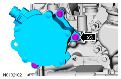
- Remove the 3 bolts and the brake vacuum pump.
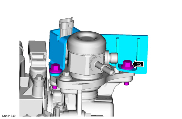
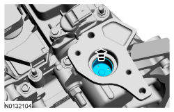
- Remove the 2 bolts and the fuel injection pump bracket.
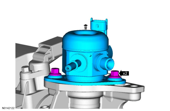
- Alternately loosen the 2 fuel injection pump bolts one complete
revolution at a time.
- Remove the fuel injection pump.
- Remove and discard the fuel injection pump O-ring seal.
- Slide the fuel injection pump tappet out of the fuel injection pump housing.
- Using the crankshaft pulley bolt, rotate the engine clockwise until the fuel injection cam lobe is at zero lift.
- Remove the 4 stud bolts and the fuel injection pump housing.
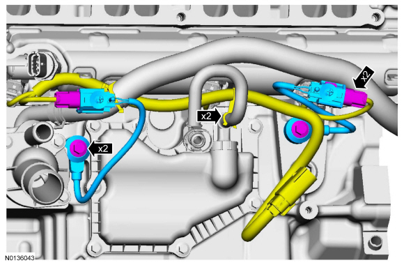
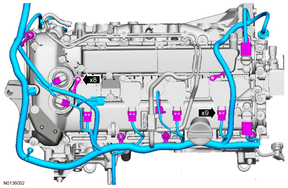
- Disconnect the 9 wiring harness electrical connectors.
- Detach the 8 retainers and remove the wiring harness from the engine.
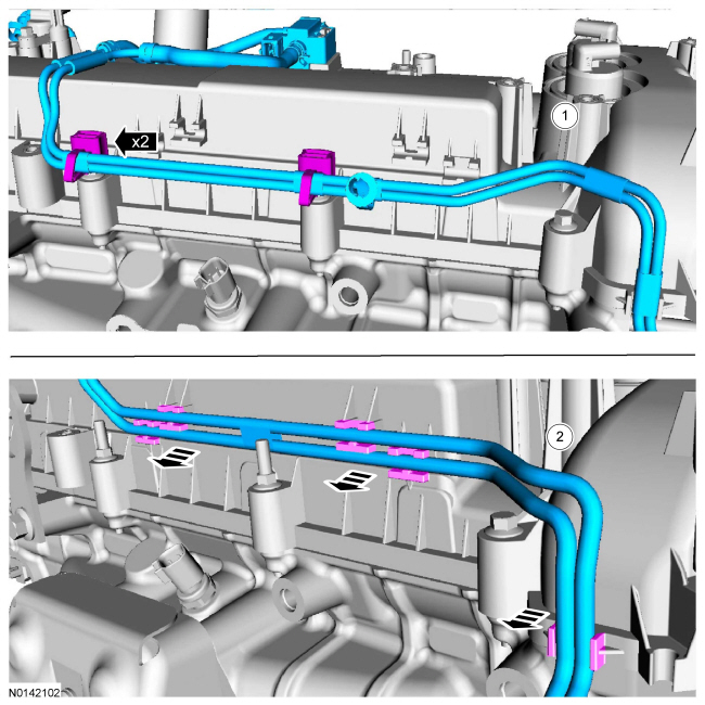
- Remove the vacuum tubes.
- Early build vehicles equipped with metal vacuum tubes.
- Late build vehicles equipped with nylon vacuum tubes.
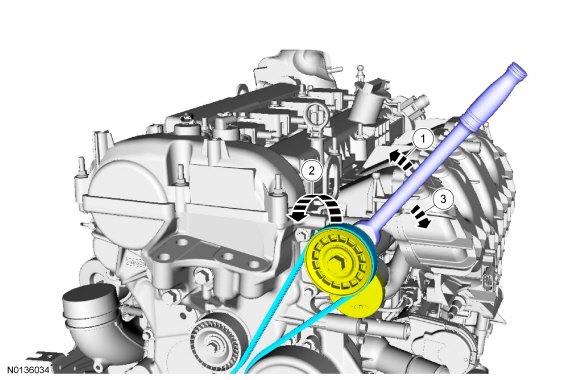
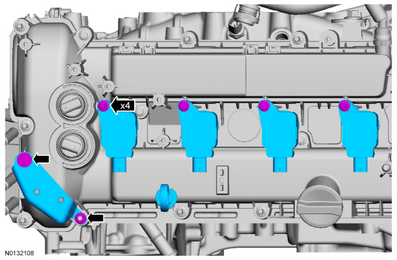
- Remove the oil level indicator.
- Remove the 4 bolts and the 4 coil-on-plugs.
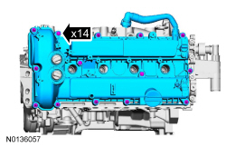
- Remove the nut, bolt and CAC intermediate tube mounting bracket.
- Loosen the 14 valve cover retainers and remove the valve cover.
- Discard the valve cover gasket.
- NOTE: The VCT solenoid seals should only be replaced if they are
damaged.
Remove any damaged VCT solenoid seals using the VCT Spark Plug Tube Seal Remover and Handle.
- Remove the 2 bolts and the rear intake camshaft cap.
- Using a wrench on the flats of the intake camshaft to prevent cam rotation, remove the brake vacuum pump adapter.
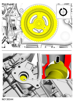
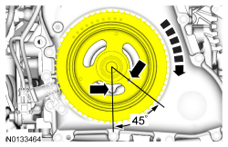
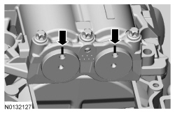
- Turn the crankshaft clockwise until the No.1 piston is 45 degrees BTDC using the guide holes on the engine front cover and the crankshaft pulley.
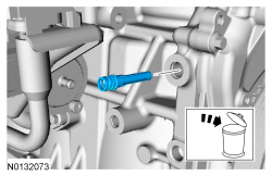
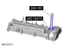
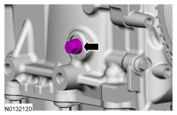
- Remove the engine plug bolt.
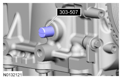
- Install the Crankshaft TDC Timing Peg.
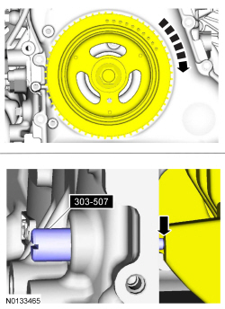
- NOTE: The Crankshaft TDC Timing Peg will contact the crankshaft
and prevent it from turning past TDC. However, the crankshaft can still be
rotated in the counterclockwise direction. The crankshaft must remain at
the TDC position during the crankshaft pulley removal and installation.
NOTE: The engine front cover is shown removed in graphic for clarity.
Rotate the crankshaft slowly clockwise until the crankshaft contacts the Crankshaft TDC Timing Peg.
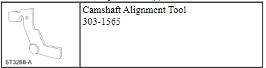
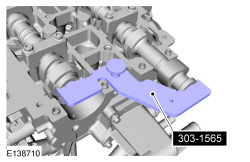
- NOTICE: The Camshaft Alignment Tool is for camshaft alignment
only. Using this tool to prevent engine rotation can result in engine
damage.
NOTE: The camshaft timing slots are offset. If the Camshaft Alignment Tool cannot be installed, remove the TDC Timing Peg and rotate the crankshaft three-fourths of a revolution clockwise and repeat the previous 2 steps of this procedure.
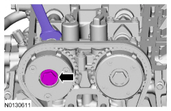
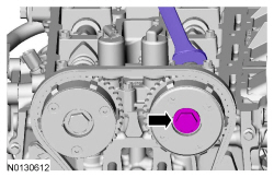
Install the Camshaft Alignment Tool into the rear of both of the camshaft slots as shown.- Tighten the retainer.
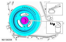
- NOTICE: The crankshaft must remain in the TDC position during
removal of the pulley bolt or damage to the engine can occur. Therefore, the
crankshaft pulley must be held in place with the Strap Wrench and the bolt
should be removed using an air impact wrench (1/2-in drive minimum).
NOTE: The crankshaft sprocket diamond washer may come off with the crankshaft pulley.
Use a Strap Wrench to hold the crankshaft pulley. Use an air impact wrench to remove the crankshaft pulley bolt.- Remove and discard the crankshaft pulley bolt and washer.
- Remove the crankshaft pulley.
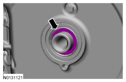
- NOTICE: The crankshaft sprocket diamond washer may come off
with the crankshaft pulley. The diamond washer should be cleaned and
inspected for any damage. If damage is evident, replace the diamond washer.
If no damage, the diamond washer is to be reused during installation. If the
diamond washer is not installed, engine damage may occur.
If the diamond washer did not come off with the crankshaft pulley, remove the diamond washer.
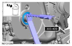
- NOTICE: Use care not to damage the engine front cover or the
crankshaft when removing the seal.
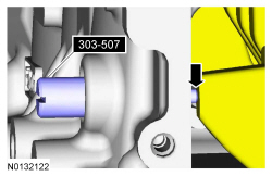
Using the Oil Seal Remover, remove the crankshaft front oil seal.
- Remove the 2 bolts and the CKP sensor.
- NOTICE: Do not use metal scrapers, wire brushes, power
abrasive disks or other abrasive means to clean sealing surfaces. These
tools cause scratches and gouges which make leak paths.
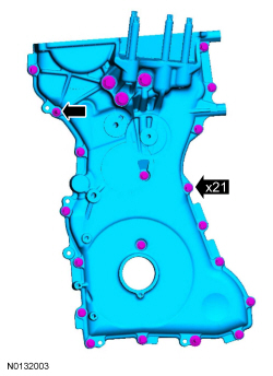
Remove the 21 bolts, the stud bolt and the engine front cover.
- Clean and inspect the mounting surfaces of the engine and the front cover.
- NOTICE: Do not rely on the Camshaft Alignment Tool to prevent
camshaft rotation. Damage to the tool or the camshaft can occur.
Using a wrench on the flats of the exhaust camshaft to prevent camshaft rotation, loosen the exhaust camshaft phaser and sprocket bolt.
- NOTICE: The Camshaft Alignment Tool is for camshaft alignment
only. Using this tool to prevent engine rotation can result in engine
damage.
Using a wrench on the flats of the intake camshaft to prevent camshaft rotation, loosen the intake camshaft phaser and sprocket bolt.
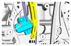
- Compress the timing chain tensioner in the following sequence.
- Using a small pick, release and hold the ratchet mechanism.
- While holding the ratchet mechanism in the released position, compress the tensioner by pushing the timing chain arm toward the tensioner.
- Insert a paper clip into the hole to retain the tensioner.
- Remove the 2 bolts and the timing chain tensioner.
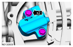
- Remove the timing chain tensioner arm.
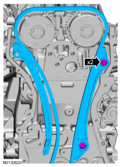
- Remove the 2 bolts and the timing chain guide.
- Remove the timing chain.
- Remove the 2 bolts and the intake and exhaust camshaft phaser and sprockets.
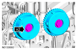
- NOTE: Washers are not required for installation of the VCT units.
If equipped, discard the washers.
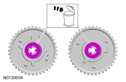
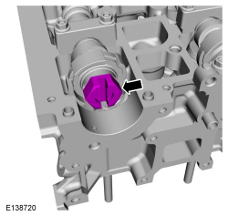
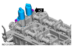
- Remove the 2 bolts and the 2 VCT solenoids.
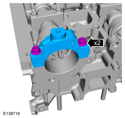
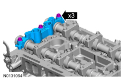
- Remove the 3 bolts and the front camshaft bearing cap.
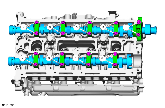
- NOTICE: Failure to follow the camshaft loosening procedure can
result in damage to the camshafts.
NOTE: Note the position of the camshaft lobes on the No. 1 cylinder for installation reference.
NOTE: Mark the location and orientation of each camshaft bearing cap.
Remove the camshafts from the engine.- Loosen the camshaft bearing caps in sequence 2 turns at a time until all tension is released from the camshaft bearing caps.
- Remove the camshaft bearing caps.
- Remove the camshafts.
- NOTE: If the camshafts and valve tappets are to be reused, mark
the location of the valve tappets to make sure they are assembled in their
original positions.
Remove the 16 valve tappets.
- NOTE: The number on the valve tappets only reflects the digits
that follow the decimal. For example, a tappet with the number 0.650 has the
thickness of 3.650 mm.
Inspect the valve tappets. For additional information, refer to Section 303-00.
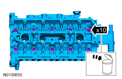
- Remove the 10 bolts and the cylinder head.
- Discard the bolts.
- NOTICE: Do not use metal scrapers, wire brushes, power
abrasive discs or other abrasive means to clean the sealing surfaces. These
tools cause scratches and gouges that make leak paths. Use a plastic
scraping tool to remove all traces of the head gasket.
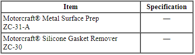
NOTE: Observe all warnings or cautions and follow all application directions contained on the packaging of the silicone gasket remover and the metal surface prep.
NOTE: Clean the cylinder head bolt holes in the cylinder block. Make sure all coolant, oil or other foreign material is removed.
NOTE: If there is no residual gasket material present, metal surface prep can be used to clean and prepare the surfaces.
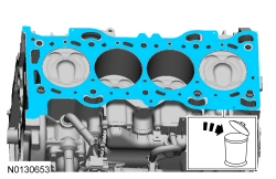
Clean the cylinder head-to-cylinder block mating surface of both the cylinder head and the cylinder block in the following sequence.- Remove any large deposits of silicone or gasket material with a plastic scraper.
- Apply silicone gasket remover, following package directions, and allow to set for several minutes.
- Remove the silicone gasket remover with a plastic scraper. A second application of silicone gasket remover may be required if residual traces of silicone or gasket material remain.
- Apply metal surface prep, following package directions, to remove any traces of oil or coolant, and to prepare the surfaces to bond with the new gasket. Do not attempt to make the metal shiny. Some staining of the metal surfaces is normal.
- NOTICE: Aluminum surfaces are soft and can be scratched
easily. Never place the cylinder head gasket surface, unprotected, on a
bench surface.
Support the cylinder head on a bench with the head gasket side up. Check the cylinder head distortion and the cylinder block distortion. For additional information, refer to Section 303-00.
- Remove and discard the head gasket.
- Remove the 2 cylinder head alignment dowels.

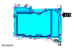
- Remove the 13 bolts and the oil pan.
- Remove the 6 bolts and the crankshaft rear seal with retainer plate.
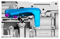
- Remove the 2 bolts and the oil pump screen and pickup tube.
- Discard the gasket.
- Remove the oil pump drive chain tensioner.
- Push the tensioner spring down and release the spring from under the shoulder bolt.
- Remove the 2 shoulder bolts and the tensioner.
- Remove the oil pump chain.
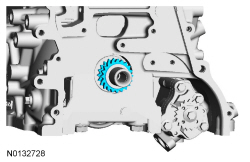
- Remove the crankshaft sprocket.
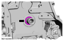
- NOTICE: The diamond washer should be cleaned and inspected for
any damage. If damage is evident, replace the diamond washer. If no damage,
the diamond washer is to be reused during installation. If the diamond
washer is not installed, engine damage may occur.
Remove the diamond washer.
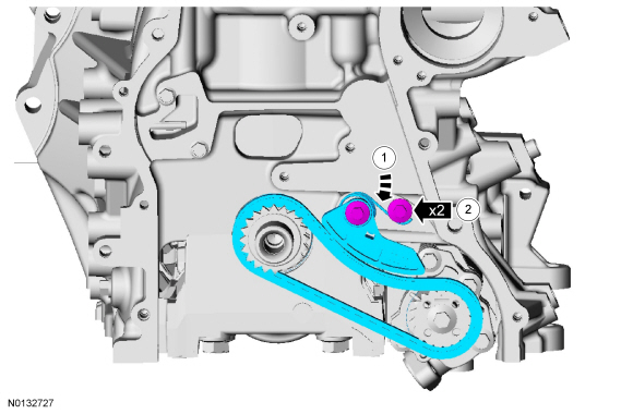
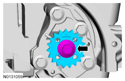
- Remove the bolt and oil pump sprocket.
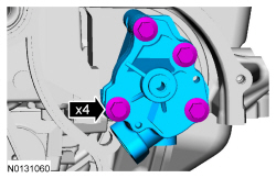
- Remove the 4 bolts and the oil pump.
- Make sure the Crankshaft TDC Timing Peg is still installed and the
engine is still at TDC.
- If necessary, rotate the crankshaft slowly clockwise until the crankshaft balance weight is up against the Crankshaft TDC Timing Peg.
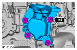
- Mark the balance shaft assembly front shafts on the top for reference that the balance shaft assembly is at TDC.
- NOTE: Due to the precision interior construction of the balance
shaft assembly, it should not be disassembled.
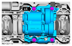
Remove the 4 bolts and the balance shaft assembly.
- Remove the Crankshaft TDC Timing Peg.

- Before removing the pistons, inspect the top of the cylinder bores. If necessary, remove the ridge or carbon deposits from each cylinder using an abrasive pad or equivalent, following manufacturer's instructions.
- NOTE: Clearly mark the connecting rods, connecting rod caps and
connecting rod bearings in numerical order for correct orientation for
reassembly.
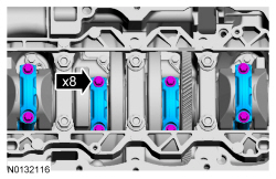
Remove the 8 bolts and the 4 connecting rod caps.
- NOTICE: Do not scratch the cylinder walls or crankshaft
journals with the connecting rod.
Remove the 4 piston and rod assemblies from the engine block.
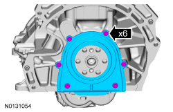
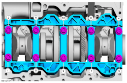
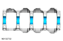
- Remove the 10 bolts in the sequence shown.
- Remove the main bearing beam.
- NOTE: If the main bearings are being reused, mark them in order
for correct orientation and reassembly.
Remove the main bearings from the main bearing beam.
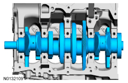
- Remove the crankshaft from the engine block.
- NOTE: If the main bearings are being reused, mark them in order
for correct orientation and reassembly. The center bulkhead has the thrust
bearing.
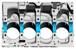
Remove the main bearings from the cylinder block.
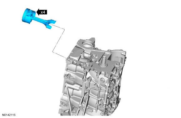
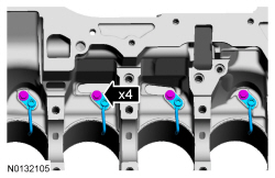
- Remove the 4 bolts and the 4 engine piston oil coolers.
 Removal
Engine
Special Tool(s)
WARNING: Do not smoke, carry lighted tobacco or have an open flame of any
type when working on or near any fuel-related component. Highly flammable
mixtures are always prese ...
 Disassembly and Assembly of Subassemblies
Cylinder Head
Special Tool(s)
Material
Disassembly
NOTICE: During engine repair procedures, cleanliness is extremely
important. Any foreign material, including any material created while cl ...
Other materials:
SYNC®
GENERAL INFORMATION
Make sure you review your device’s manual before using it with SYNC.
Support
The SYNC support team is available to help you with any questions you
cannot answer on your own.
Monday-Saturday, 8:30am-9:00pm EST.
Sunday, 10:30am-7:30pm EST.
In the United States, call: ...
Specifications, Description and Operation, Diagnosis and Testing
SPECIFICATIONS
Material
General Specifications
Torque Specifications
a Refer to the procedure in this section.
b 15 Nm plus an additional 60 degrees
c 8 Nm plus an additional 180 degrees
DESCRIPTION AND OPERATION
Engine
Overview
The 2.0L GTDI 4-cylinder engine has ...
Cabin air filter
Note: Make sure you have a cabin air filter installed at all times. This
prevents foreign objects from entering the system. Running the system
without a filter in place could result in degradation or damage to the
system.
Your vehicle is equipped with a cabin air filter, which is located just ...
