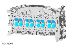
Cylinder Head
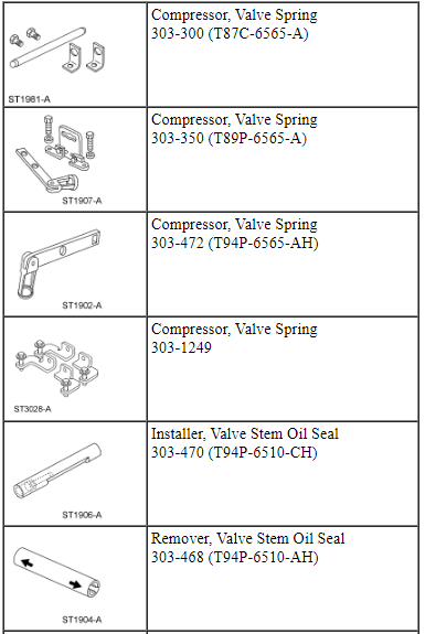
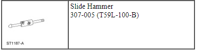
Special Tool(s)
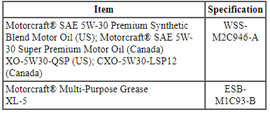
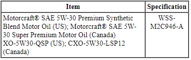
Material
Disassembly
NOTICE: During engine repair procedures, cleanliness is extremely important. Any foreign material, including any material created while cleaning gasket surfaces, that enters the oil passages, coolant passages or the oil pan can cause engine failure.
NOTICE: Aluminum surfaces are soft and can be scratched easily. Never place the cylinder head gasket surface, unprotected, on a bench surface.
NOTE: If the components are to be reinstalled, mark the location of the components removed, they must be installed in the same location.
- NOTE: RH shown, LH similar.
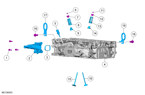
Remove the 2 bolts and the LH and RH engine lift eyes.

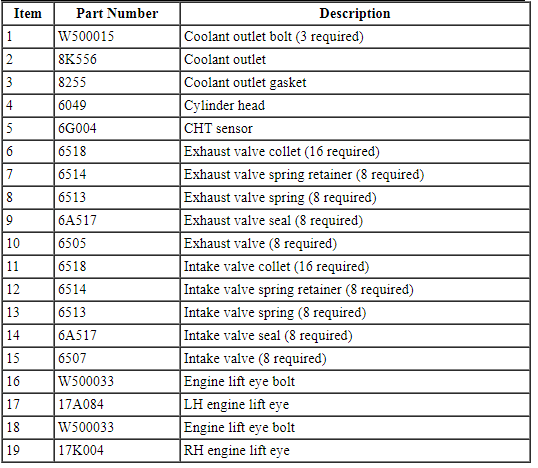
- Remove the 3 bolts and the coolant outlet and gasket.
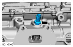
- Remove and discard the CHT sensor.

- NOTE: Place all parts in order to one side.
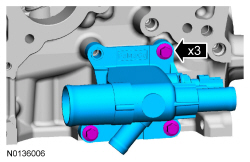
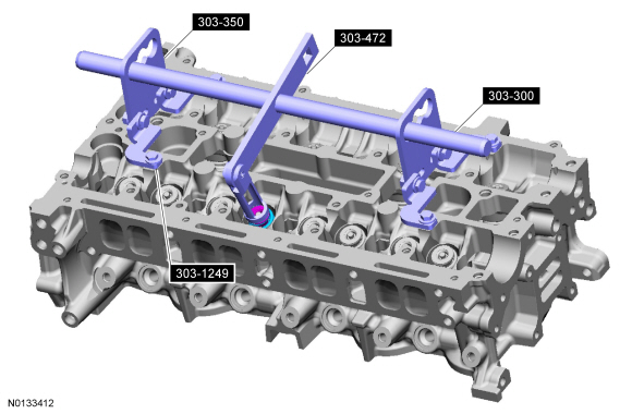
Remove the valve spring.
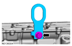
- Using the Valve Spring Compressors, compress the valve spring and remove the valve collet, using some multi-purpose grease and a small screwdriver.
- Remove the valve spring retainer and the valve spring.
- Inspect the valve springs. For additional information, refer to Section 303-00.
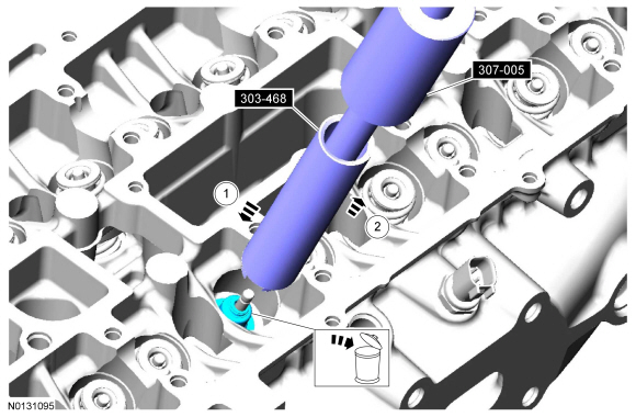
- Remove and discard the valve seal.
- Position the Valve Stem Oil Seal Remover and Slide Hammer over the seal.
- Pull up on the Slide Hammer and Valve Stem Oil Seal Remover and remove the seal.
- NOTE: Mark each valve location if the original valves are to be
used.
Remove the valves.
- Inspect the valves. For additional information, refer to Section 303-00.

Assembly
- NOTE: If installing the original valves, make sure the valves are
installed in the same position from which they were removed.
Coat the valve stems with clean engine oil and install the valves.
- NOTE: Lubricate the valve seal with clean engine oil prior to
installing.
Using the Valve Stem Oil Seal Installer, install the valve seal.
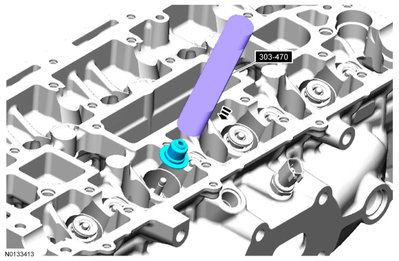
- NOTE: Check the seating of the valve collet.
Install the valve spring and the valve spring retainer.
- Compress the valve spring and install the valve collet using some grease and a small screwdriver.

- Install a new CHT sensor.
- Tighten to 11 Nm (97 lb-in).
- Inspect the gasket and replace if necessary.
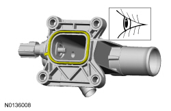
- Install the gasket, coolant outlet and the 3 bolts.
- Tighten to 10 Nm (89 lb-in).

- NOTE: RH shown, LH similar.
Install the LH and RH engine lift eyes and the 2 bolts.
- Tighten to 47 Nm (35 lb-ft).
Piston
Material
Disassembly
NOTE: If the piston and connecting rod are to be reinstalled, they must be assembled in the same orientation. Mark the piston orientation to the connecting rod reassembly.
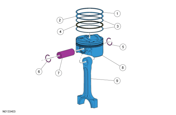
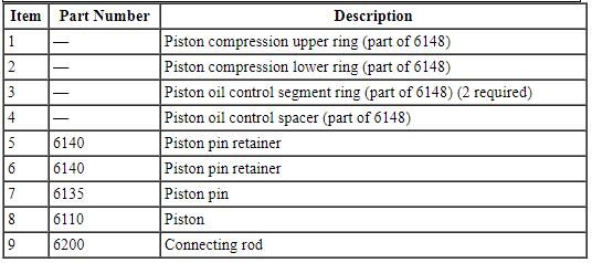
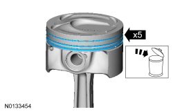
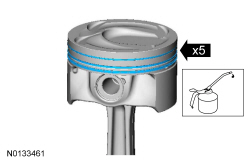
- Remove and discard the piston rings.
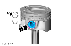
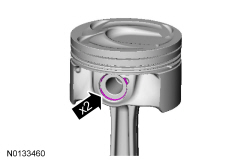
- Remove and discard the 2 piston pin retainers.
- Remove the piston pin.
- Separate the piston from the connecting rod.
- Clean and inspect the piston and connecting rod. For additional information, refer to Section 303-00.
Assembly
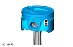
- Align the piston-to-connecting rod orientation marks and position the piston on the connecting rod.

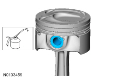
- NOTE: Lubricate the piston pin and pin bore with clean engine
oil.
Install the piston pin in the piston and connecting rod assembly.
- Install the 2 new piston pin retainers in the piston.
- NOTE: Lubricate the piston and the new piston rings with clean
engine oil.
Install the piston rings on the piston.
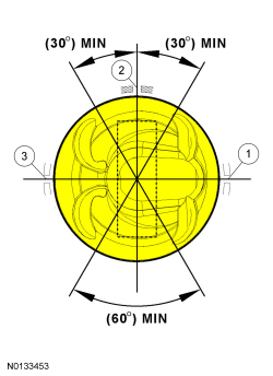
- Align the piston rings on the piston.
- Upper oil control segment ring gap location
- Oil control spacer gap location
- Lower oil control segment ring gap location
 Disassembly
Engine
Special Tool(s)
Material
NOTICE: Do not loosen or remove the crankshaft pulley bolt without
first installing the special tools as instructed in this procedure. The
crankshaft pulley ...
 Assembly
Engine
Special Tool(s)
Material
Engine - External Components
Engine - Front and Upper Components
Engine - Lower Block Components
NOTICE: Do not loosen or remove the crankshaft pulley ...
Other materials:
Adding Engine Oil
Note: Do not remove the filler cap when the engine is running.
Note: Do not add engine oil further than the MAX mark. Oil levels above
the MAX mark may cause engine damage.
Only use oils certified for gasoline engines by the
American Petroleum Institute (API). An oil with this
trademark sym ...
Engine Emission Control
SPECIFICATIONS
Material
Torque Specifications
DESCRIPTION AND OPERATION
Engine Emission Control
Component Locations
2.0L GTDI
3.5L Ti-VCT and
3.7L Ti-VCT
3.5L GTDI
System Operation
Refer to the PC/ED manual
section 1 Description and Operation.
Component ...
Rear seats
Split-folding Rear Seat
WARNING: Before returning the seatback to its original position,
make sure that cargo or any objects are not trapped behind the
seatback. After returning the seatback to its original position, pull on
the seatback to make sure that it has fully latched. An unlatched seat
...
