DESCRIPTION AND OPERATION
Instrument Cluster and Panel Illumination
Overview
Dimmable Backlighting
Dimmable illumination provides backlighting to certain switches and control components when the parking lamps are on. The level of backlighting intensity is adjusted by instrument panel dimmer switch.
Non-Dimmable Backlighting
Non-dimmable illumination provides backlighting to the door lock, roof opening panel and window control switches when the accessory relay is energized.
System Operation
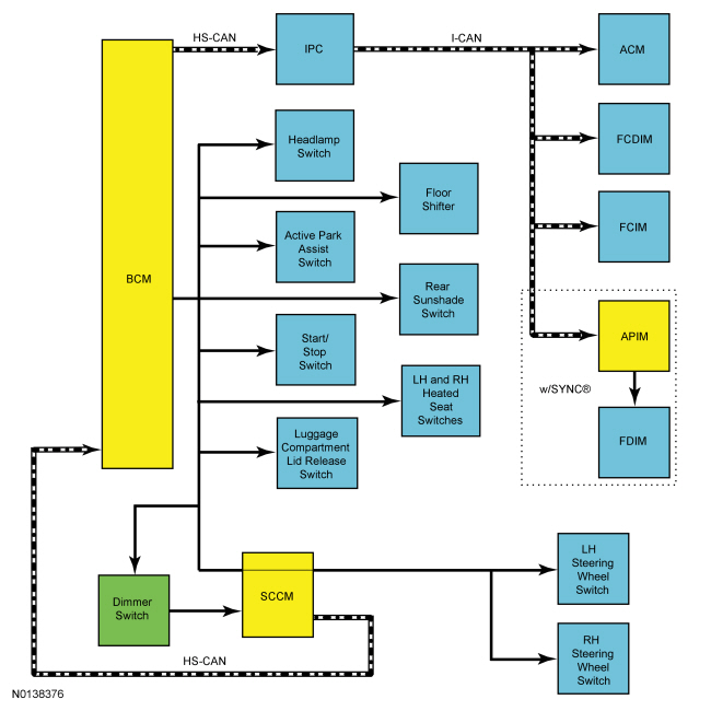
System Diagram
Network Message Chart
Network Input Messages - IPC
Network Input Messages - ACM, APIM, FCIM and FCDIM
Network Input Messages - BCM
Dimmable Backlighting
The dimmable switches and components are illuminated when the parking lamps are on. The instrument panel dimmer switch controls all dimmable interior illuminated components. On vehicles equipped with autolamps, if the exterior lamps are activated during the daytime, the message center illumination remains at full intensity and does not dim from the instrument panel dimmer switch during this condition. If the vehicle travels under a bridge or a tunnel, the low level of ambient light causes the illumination level of the message center to change to the level set by the instrument panel dimmer switch. The message center illumination changes back to full intensity when the intense ambient light is restored.
When the parking lamps are on, the SCCM monitors the input from the instrument panel dimmer switch. The SCCM sends a message to the BCM over the HS-CAN relaying the instrument panel dimmer switch input. Based this message, the BCM sends a pulse-width modulated voltage to the dimmable switches.
The BCM also sends an illumination dimming level message over the network to control the backlighting intensity of networked modules. If a receiving module deems data received from the BCM invalid for 5 seconds or less, the receiving module defaults the backlighting to the last setting.
If the receiving module does not receive the illumination dimming level message from the BCM or if the data received is deemed invalid for more than 5 seconds, the receiving module sets a DTC in continuous memory and defaults the backlighting to full nighttime intensity.
Non-Dimmable Backlighting
When the accessory delay relay is energized, switched voltage is supplied to the window control, roof opening panel and door lock control switches. REFER to Section 501-11.
Field-Effect Transistor (FET) Protection
REFER to Section 419-10.
Component Description
Dimmer Switch
The instrument panel dimmer switch is a double detent rocker switch used to control all dimmable interior illuminated components and the courtesy lamps. The first up detent increases dimmable backlighting intensity. The first down detent decreases dimmable backlighting intensity. The second up detent turns the courtesy lamps on. The second down detent turns the courtesy lamps off (allowing other features to control the courtesy lamps).
DIAGNOSIS AND TESTING
Instrument Cluster and Panel Illumination
DTC Charts
Diagnostics in this manual assume a certain skill level and knowledge of Ford-specific diagnostic practices. REFER to Section 100-00 for information regarding these diagnostic practices.
Related Module DTC Chart - BCM
Related Module DTC Chart - SCCM
Symptom Chart
Diagnostics in this manual assume a certain skill level and knowledge of Ford-specific diagnostic practices. REFER to Section 100-00 for information regarding these diagnostic practices.
Pinpoint Tests
Pinpoint Test A: All Dimmable Illumination Does Not Dim
Diagnostic Overview
Diagnostics in this manual assume a certain skill level and knowledge of Ford-specific diagnostic practices. Refer to Diagnostic Methods in Section 100-00 for information about these practices.
Refer to Wiring Diagrams Cell 71, Cluster and Panel Illumination for schematic and connector information.
Normal Operation and Fault Conditions
REFER to Instrument Cluster and Panel Illumination.
DTC Fault Trigger Conditions
Possible Sources
- Wiring, terminals or connectors
- Instrument panel dimmer switch
- SCCM
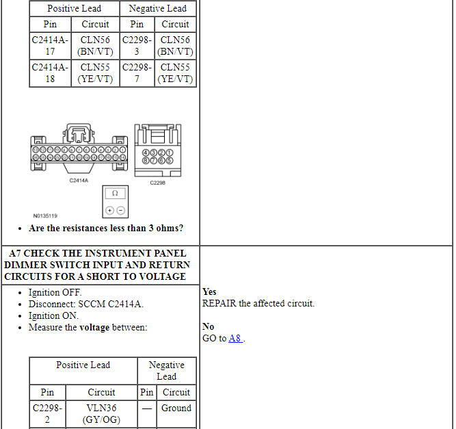
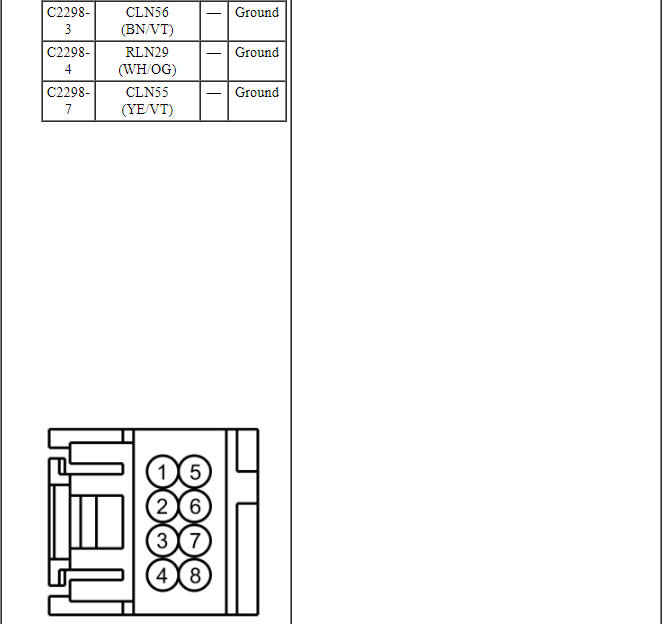
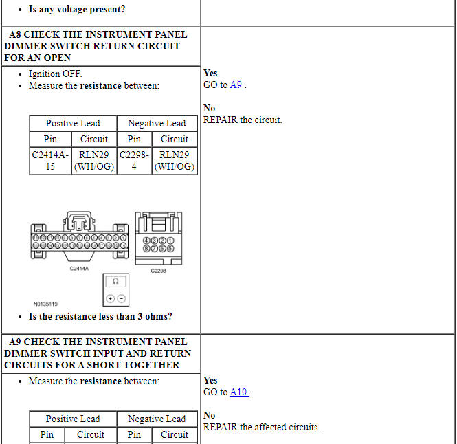
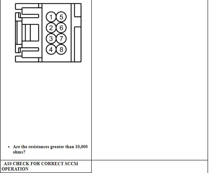
PINPOINT TEST A: ALL DIMMABLE ILLUMINATION DOES NOT DIM
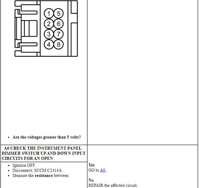
Pinpoint Test B: All Dimmable Non-Networked Illumination Is Inoperative
Diagnostic Overview
Diagnostics in this manual assume a certain skill level and knowledge of Ford-specific diagnostic practices. Refer to Diagnostic Methods in Section 100-00 for information about these practices.
Refer to Wiring Diagrams Cell 71, Cluster and Panel Illumination for schematic and connector information.
Normal Operation and Fault Conditions
REFER to Instrument Cluster and Panel Illumination.
DTC Fault Trigger Conditions
Possible Sources
- BCM fuse 12 (15A)
- Wiring, terminals or connectors
- BCM
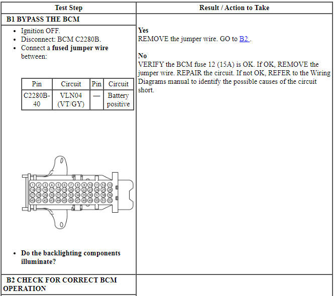
PINPOINT TEST B: ALL DIMMABLE NON-NETWORKED ILLUMINATION IS INOPERATIVE
Pinpoint Test C: All Dimmable Non-Networked Illumination Is Always On
Diagnostic Overview
Diagnostics in this manual assume a certain skill level and knowledge of Ford-specific diagnostic practices. Refer to Diagnostic Methods in Section 100-00 for information about these practices.
Refer to Wiring Diagrams Cell 71, Cluster and Panel Illumination for schematic and connector information.
Normal Operation and Fault Conditions
REFER to Instrument Cluster and Panel Illumination.
DTC Fault Trigger Conditions
Possible Sources
- Wiring, terminals or connectors
- BCM
PINPOINT TEST C: ALL DIMMABLE NON-NETWORKED ILLUMINATION IS ALWAYS ON
Pinpoint Test D: The Steering Wheel Switch Illumination Is Inoperative
Diagnostic Overview
Diagnostics in this manual assume a certain skill level and knowledge of Ford-specific diagnostic practices. Refer to Diagnostic Methods in Section 100-00 for information about these practices.
Refer to Wiring Diagrams Cell 71, Cluster and Panel Illumination for schematic and connector information.
Normal Operation and Fault Conditions
REFER to Instrument Cluster and Panel Illumination.
Possible Sources
- Wiring, terminals or connectors
- Steering wheel switch(es)
- Steering wheel harness
- Clockspring
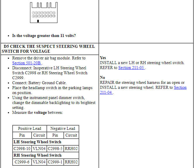
PINPOINT TEST D: THE STEERING WHEEL SWITCH(ES) ILLUMINATION IS INOPERATIVE
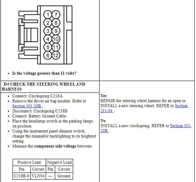
Pinpoint Test E: One Or More Switch Or Component Illumination Is Inoperative
Diagnostic Overview
Diagnostics in this manual assume a certain skill level and knowledge of Ford-specific diagnostic practices. Refer to Diagnostic Methods in Section 100-00 for information about these practices.
Refer to Wiring Diagrams Cell 71, Cluster and Panel Illumination for schematic and connector information.
Normal Operation and Fault Conditions
REFER to Instrument Cluster and Panel Illumination.
Possible Sources
- Wiring, terminals or connectors
- Illuminated switch
- Illuminated component
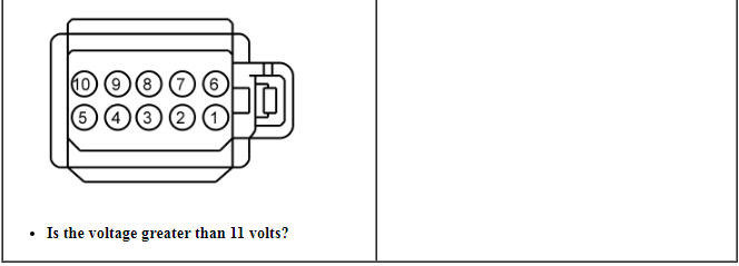
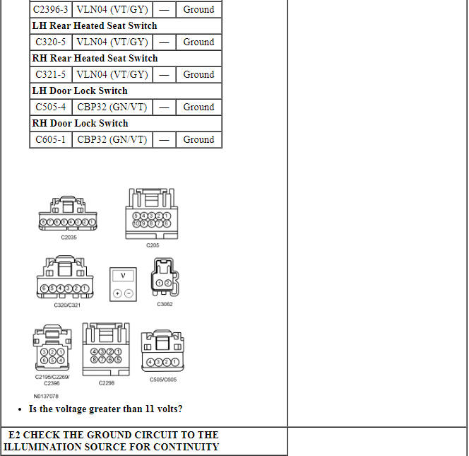
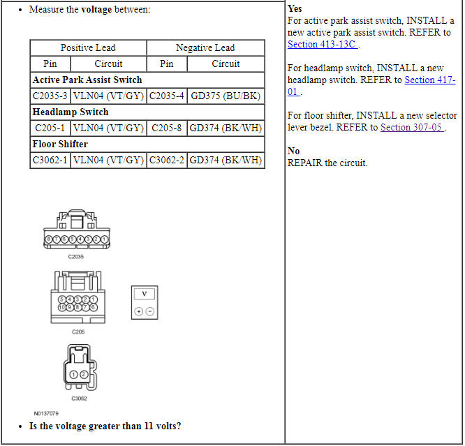
PINPOINT TEST E: ONE OR MORE ILLUMINATION SOURCE IS INOPERATIVE
REMOVAL AND INSTALLATION
Instrument Cluster Bulb
Removal and Installation
- Remove the Instrument Panel Cluster (IPC). For additional information, refer to Section 413-01.
- Rotate the bulb one-quarter turn counterclockwise and lift it out from the IPC.
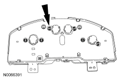
- To install, reverse the removal procedure.
Selector Lever Indicator Bulb
Removal and Installation
- Remove the transmission selector lever bezel. For additional information, refer to Section 307-05.
- Remove the selector lever indicator bulb from the socket.
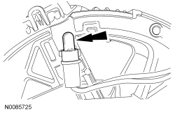
- To install, reverse the removal procedure.
Instrument Panel Dimmer Switch
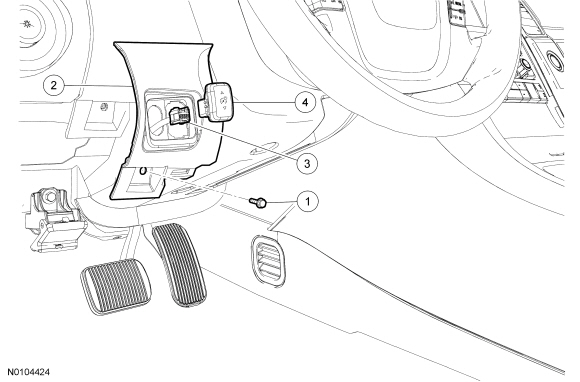
Removal and Installation
- Remove the steering column opening trim panel. For additional information, refer to Instrument Panel - Exploded View in Section 501-12.
- Remove the instrument panel dimmer switch bezel retaining screw and pull
off the bezel.
- Disconnect the electrical connector.
- Release the tabs and remove the instrument panel dimmer switch.
- To install, reverse the removal procedure.


Other materials:
Body System - General Information
SPECIFICATIONS
Material
DESCRIPTION AND OPERATION
Insulation
Insulation is used as a sound-deadener to reduce exterior road and powertrain
noises from the interior of the vehicle. Mastic insulators are also used as
insulation. For information on the location of the mastic insulators, refer
to&nb ...
Troubleshooting
Your SYNC system is easy to use. However, should questions arise,
see the tables below.
Use the website at any time to check your phoneŌĆÖs compatibility,
register your account and set preferences as well as access a
customer representative via an online chat (during certain hours).
Visit w ...
MyFord Touch® (If Equipped)
INTRODUCTION
WARNING: Driving while distracted can result in loss of vehicle
control, crash and injury. We strongly recommend that you use
extreme caution when using any device that may take your focus off
the road. Your primary responsibility is the safe operation of your
vehicle. We recommend ...
