SPECIFICATIONS
Material
Torque Specifications
DESCRIPTION AND OPERATION
Fuel Charging and Controls
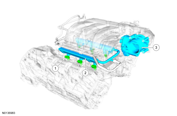
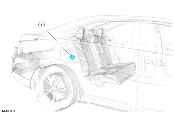
Component Locations
WARNING: Do not smoke, carry lighted tobacco or have an open flame of any type when working on or near any fuel-related component. Highly flammable mixtures are always present and may be ignited. Failure to follow these instructions may result in serious personal injury.
NOTICE: Handle the fuel injectors and fuel rail with extreme care to prevent damage to the fuel inlet of the fuel rail, fuel injector sealing areas, and sensitive fuel-metering orifices.
3.7L Ti-VCT
FPCM
System Operation
REFER to the PC/ED manual section 1 Description and Operation.
Component Description
REFER to the PC/ED manual section 1 Description and Operation.
DIAGNOSIS AND TESTING
Fuel Charging and Controls
For PCM DTCs, REFER to Section 303-14, PCM DTC Chart. For driveability symptoms without DTCs, refer to the Powertrain Control/Emissions Diagnosis (PC/ED) manual, section 3 Symptom Charts.
REMOVAL AND INSTALLATION
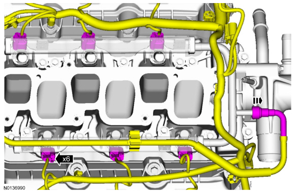
Fuel Injectors
Removal and Installation
- The fuel injectors are serviced with the fuel rail. For additional information, refer to Fuel Rail.
Fuel Rail
Material
Removal and Installation
WARNING: Do not smoke, carry lighted tobacco or have an open flame of any type when working on or near any fuel-related component. Highly flammable mixtures are always present and may be ignited. Failure to follow these instructions may result in serious personal injury.
WARNING: Before working on or disconnecting any of the fuel tubes or fuel system components, relieve the fuel system pressure to prevent accidental spraying of fuel. Fuel in the fuel system remains under high pressure, even when the engine is not running. Failure to follow this instruction may result in serious personal injury.
WARNING: Clean all fuel residue from the engine compartment. If not removed, fuel residue may ignite when the engine is returned to operation. Failure to follow this instruction may result in serious personal injury.
WARNING: Always disconnect the battery ground cable at the battery when working on an evaporative emission (EVAP) system or fuel-related component. Highly flammable mixtures are always present and may be ignited. Failure to follow these instructions may result in serious personal injury.
WARNING: Do not carry personal electronic devices such as cell phones, pagers or audio equipment of any type when working on or near any fuel-related component. Highly flammable mixtures are always present and may be ignited. Failure to follow these instructions may result in serious personal injury.
NOTE: Removal steps in this procedure may contain installation details.
- Release the fuel system pressure. For additional information, refer to Section 310-00.
- Disconnect the battery ground cable. For additional information, refer to Section 414-01.
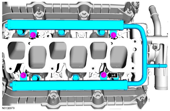
- Remove the upper intake manifold. For additional information, refer to Section 303-01D.
-
- Tighten to 10 Nm (89 lb-in).

- For additional information, refer to Section 310-00.
-
- Tighten to 10 Nm (89 lb-in).
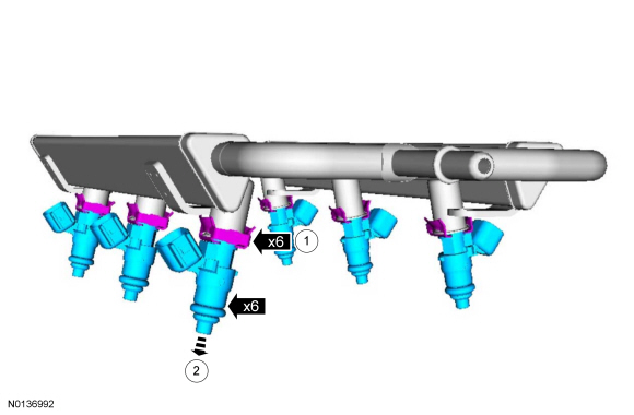
- NOTE: Make sure that a new upper and lower fuel injector O-ring
seals are installed.
Discard the specified component. Follow local disposal regulations.
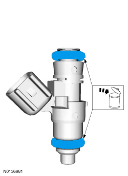
- NOTICE: Use O-ring seals that are made of special
fuel-resistant material. The use of ordinary O-rings seals can cause the
fuel system to leak. Do not reuse the O-ring seals.
NOTE: The upper and lower fuel injector O-ring seals are similar in appearance but are not interchangeable.
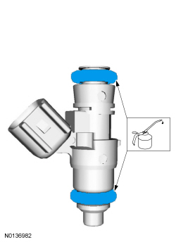
NOTE: Install new fuel injector O-ring seals and lubricate them with clean engine oil.
Apply the specified lubricant to the specified component.
- To install, reverse the removal procedure.
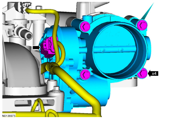
Throttle Body
NOTE: Removal steps in this procedure may contain installation details.
- Remove the Air Cleaner (ACL) outlet pipe. For additional information, refer to Section 303-12.
-
- Tighten to 10 Nm (89 lb-in).
- NOTE: Make sure that a new TB gasket is installed.
- Discard the specified component. Follow local disposal regulations.
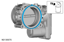
- To install, reverse the removal procedure.
 Fuel Charging and Controls - Turbocharger, 2.0L GTDI
SPECIFICATIONS
Torque Specifications
a Refer to the procedure in this section.
DESCRIPTION AND OPERATION
Turbocharger
Component Location
Overview
NOTICE: Whenever turbocharger air intake ...
 Accessory Drive
SPECIFICATIONS
Torque Specifications
DESCRIPTION AND OPERATION
Accessory Drive
Component Location
2.0L GTDI
3.5L TiVCT, 3.7L TiVCT and 3.5L GTDI
Overview
The accessory drive system provides power ...
Other materials:
Diagnosis and Testing
Handles, Locks, Latches and Entry Systems
Special Tool(s)
Material
DTC Chart
Diagnostics in this manual assume a certain skill level and knowledge of
Ford-specific diagnostic practices. Refer to Diagnostic Methods in Section
100-00 for information about these practices.
BCM DTC Ch ...
Hydraulic Brake Actuation
SPECIFICATIONS
Material
Torque Specifications
DESCRIPTION AND OPERATION
Adjustable Pedals
Overview
The adjustable pedal feature uses an electrical motor to adjust the brake and
accelerator pedal positions forward and rearward to increase driver comfort. Two
adjustable pedal systems are available ...
Diagnosis and Testing
Roof Opening Panel
Special Tool(s)
Principles of Operation
Roof Opening Panel
The roof opening panel assembly uses an integrated motor and module to
operate the roof opening panel. The roof opening panel motor and module are
installed new as an assembly. The roof opening panel is an electronicall ...
