Accessing Mounting Bolts On an Inoperative Power Seat
General Equipment
- Drill(s)
WARNING: Wear protective gloves when handling components or parts that have pointed or sharp edges. Failure to follow this instruction may result in serious personal injury.
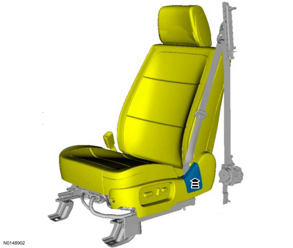
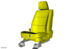
NOTE: Typical driver seat shown, other seats similar.
- If equipped.
- If equipped.
- If equipped, passenger seat.
- If equipped.
- If equipped with Active Motion massage.
-
- -
- -
- -
- If equipped with Active Motion massage.
- NOTE: Connectors and location may vary due to vehicle configuration.
- If equipped with Active Motion massage.
- If equipped, passenger seat with bladder OCS.
- If equipped with climate controlled seats.
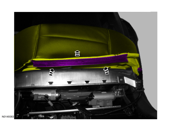
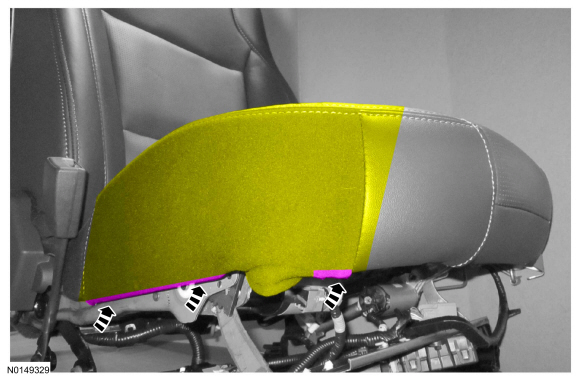
- NOTE: Note the position of the cushion support wires for
installation.
On both sides.
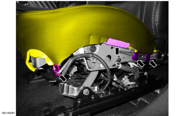
- NOTE: Seat cushion wire harness take-outs will vary with seat option content. Note the wire harness routing, attachment points and connections to the horizontal seat motor and bracket for installation.
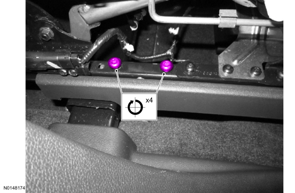
- NOTE: Pushing the seat forward or backward can aid in bolt hole
alignment.
On both sides.
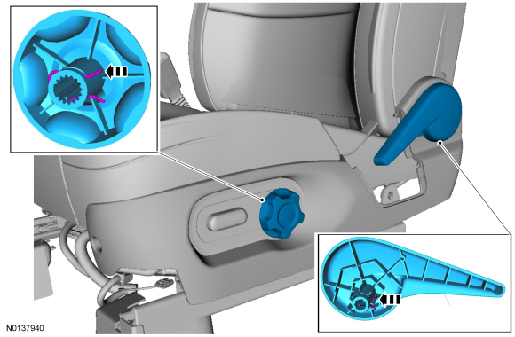
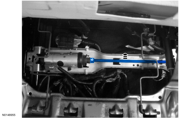
- NOTICE: When using a drill to move the seat track, do not move
the seat track to its forward or rearward end of travel stops. Doing so can
result in damage to the seat track requiring its replacement.
NOTE: Be sure to drive the seat track evenly or the track will bind during movement.
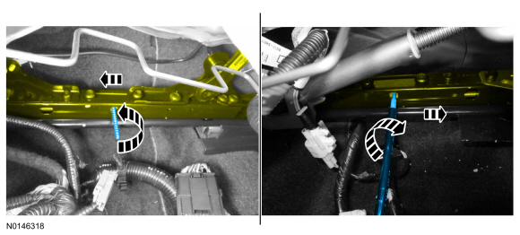
NOTE: Rotate the cables using 2 drills operating at similar speeds to most efficiently position the seat track.
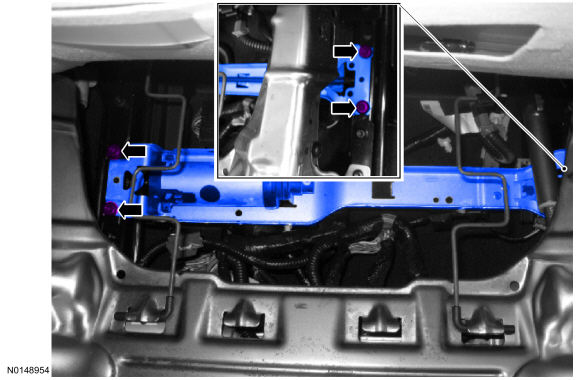
Insert both seat track cables then drive the inboard and outboard seat tracks forward until the rear mounting bolts are accessible.
General Equipment: Drill(s).
- Remove the front seat. Refer to Seat - Front.
- Install the front seat track motor. Refer to Seat Track Motor - Front.
Do not install the seat at this time.
- If equipped, transfer the seat position sensor. Refer to Section 501-20B
- NOTE: Install as noted during removal.
On both sides.

- If equipped with climate controlled seats.
- If equipped, passenger seat with bladder OCS.
- If equipped with Active Motion massage.

- NOTE: Connectors and location may vary due to vehicle configuration.
-
- If equipped with Active Motion massage.
- -
- -
- -
- If equipped with Active Motion massage.

- If equipped.
- Install the front seat. Refer to Seat - Front. If a passenger seat with a bladder OCS has been serviced, do not prove out the SRS within the seat installation procedure. Proceed to the next step here after the seat has been installed in the vehicle and repower has been done.
- For a passenger seat with a bladder OCS, carry out the OCS reset. Refer to Section 501-20B.
- If equipped with memory seat, operate the horizontal motor in both directions through the full range of travel to allow the DSM to correctly register stop positions and prevent premature stopping points after the repair is complete.
Memory Position Programming
Recalling a Stored Memory Position
NOTE: A memory recall can be initiated only if the vehicle is in PARK or NEUTRAL and the ignition is not in START. A memory recall in progress will not be affected by moving the ignition to START or by moving the gearshift lever out of PARK or NEUTRAL.
NOTE: Input from the driver seat control switch, memory SET switch, pedal adjust switch (if equipped), exterior mirror control switch (if equipped) and steering column control switch (if equipped) during a memory recall will abort the operation.
- The driver can recall the desired memory driver seat, memory exterior mirrors (if equipped), memory adjustable pedals (if equipped) and memory steering column (if equipped) positions by pressing either memory SET switch button 1 or 2. Pressing memory SET switch button 1 will initiate a recall of the positions stored for memory 1. Pressing memory SET switch button 2 will initiate a recall of the positions stored for memory 2.
Programming Memory Positions
NOTE: Memory positions can be stored at any time.
NOTE: Verify good battery condition before diagnosing the memory seat system. Poor battery condition may interfere with memory seat operation, even if vehicle starting is possible.
- Place the ignition to ON.
- NOTE: To program the Remote Keyless Entry (RKE) transmitter,
refer to Section 501-14B.
To set memory position(s) move the memory driver seat, memory exterior mirror (if equipped), memory adjustable pedals (if equipped) and memory steering column (if equipped) to the preferred position using the appropriate switch(es).
- NOTE: Input from the driver seat control switch, pedal adjust
switch (if equipped), exterior mirror control switch (if equipped) and
steering column control switch (if equipped) during memory programming will
abort the operation.
NOTE: If other tones or chimes are being produced, the memory save tone will not be heard because it is one of the lowest priorities.
Press and hold a memory button (1 or 2) until a tone is heard (1.5 seconds). When the tone is heard, the memory programming is complete.
- Repeat the previous steps to program another memory position.
Seat Wire Harness Routing
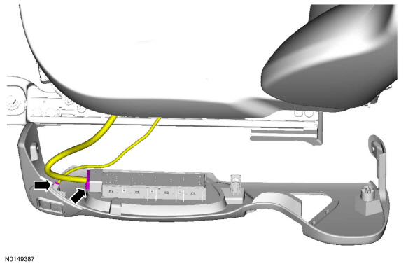
- For correct front passenger seat cushion wire harness routing with
Occupant Classification System (OCS) weight sensor bolts, refer to the
following views.
- Match the numbers in the wire harness view to the numbers in the retainer and connector location views and attach accordingly.
- Wire harness retainers and electrical connectors are called out in assembly order.
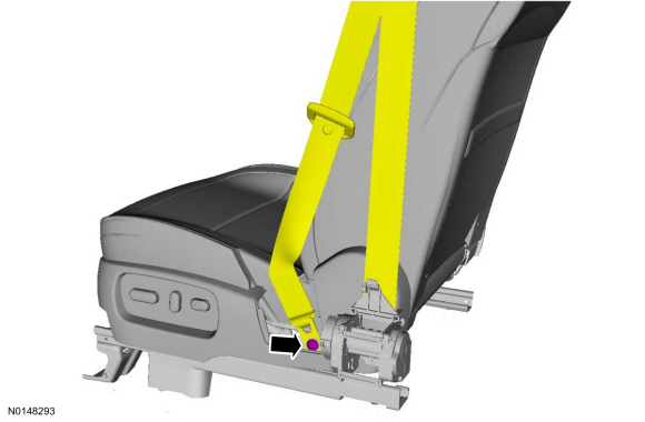
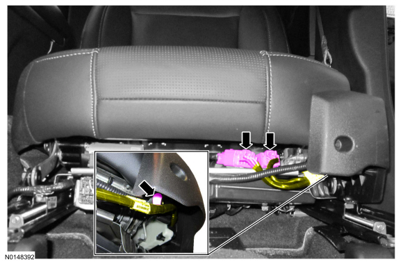
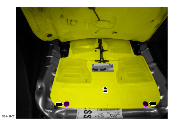
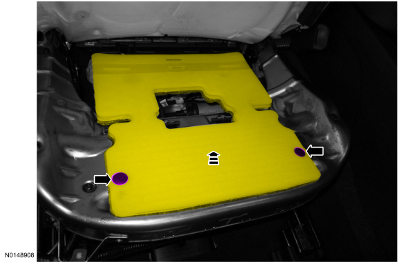
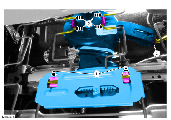
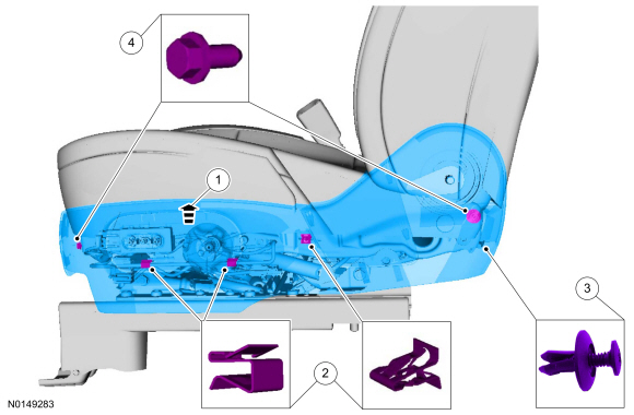
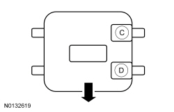
- NOTE: Illustration shows the OCS weight sensor bolts in their
installed position with the seat in the vehicle (arrow indicates front).
Verify the correct passenger seat OCS weight sensor bolt electrical connector positions using the illustration.
- For correct identification and placement of the 2 OCS weight sensor bolt electrical connectors, use the wire colors identified in Wiring Diagrams manual Cell 46. Connecting the incorrect connector to a sensor will cause DTCs to set and will result in an unsuccessful OCS system reset.
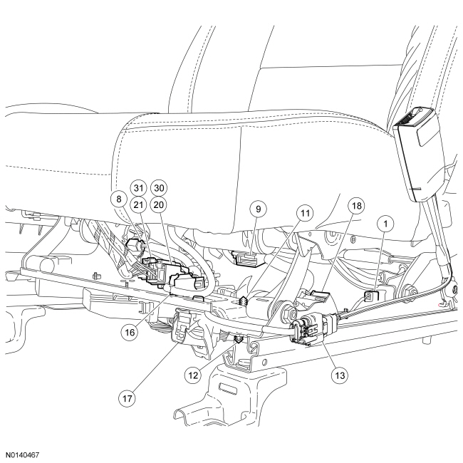
Passenger Seat With Weight Sensor Bolt Occupant Classification System (OCS) (Active Motion Massage)
Wire Harness View
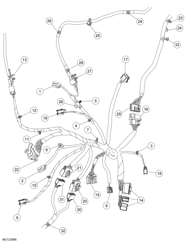
- OCS weight sensor bolt C electrical connector
- OCS weight sensor bolt D electrical connector
- Seat position sensor wire harness retainer
- Horizontal motor sensor wire harness retainer
- OCS weight sensor bolt C wire harness retainer
- OCS weight sensor bolt D wire harness retainer
- Wire harness main retainer
- Rear height motor electrical connector
- Front height motor electrical connector
- Front height motor wire harness retainer
- Safety belt buckle wire harness retainer
- Safety belt buckle wire harness retainer
- Safety belt buckle electrical connector and retainer
- Dual Climate Controlled Seat Module (DCSM) electrical connectors
- Occupant Classification System Module (OCSM) electrical connector
- Seat-to-backrest wire harness electrical connector and retainer
- Cushion Thermo-Electric Device (TED) electrical connector
- Seat position sensor electrical connector
- Horizontal motor electrical connector
- Seat control switch electrical connector and retainer (large)
- Seat control switch electrical connector and retainer (large)
- Seat-to-body harness electrical connector and retainer
- Backrest wire harness retainer
- Side air bag wire harness retainers
- Side air bag wire harness retainer
- Side air bag wire harness retainers
- Side air bag electrical connector and retainer
- Side air bag wire harness retainers
- Seat-to-backrest wire harness electrical connector
- Seat control switch electrical connector (small)
- Seat control switch electrical connector (small)
- Seat control switch electrical pigtail retainer
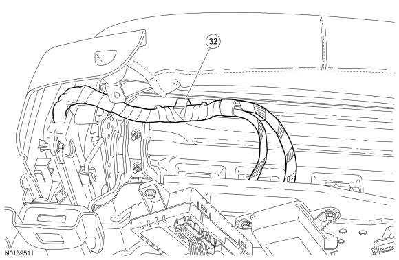
- Backrest wire harness retainer
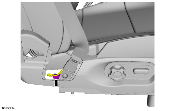
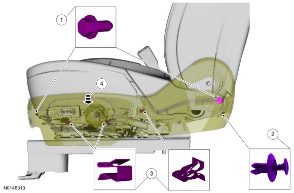
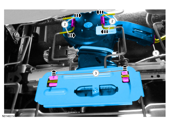
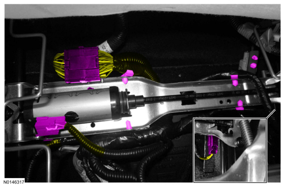
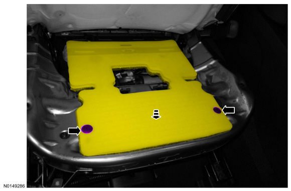
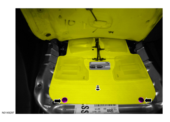
Wire Harness Retainer and Connector Location View, Underneath
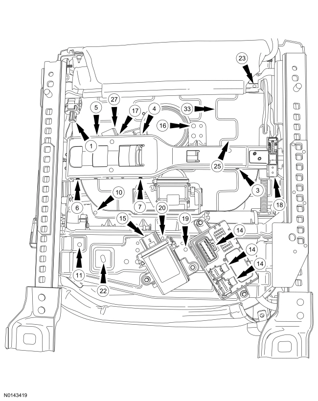
Wire Harness Retainer and Connector Location View, Front of Seat
Wire Harness Retainer and Connector Location View, Inboard Side
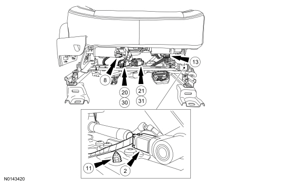
Wire Harness Retainer and Connector Location View, Front of Seat Underneath
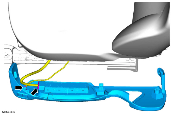
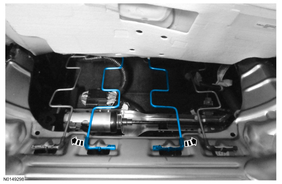
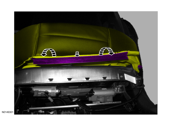
Wire Harness Installed View
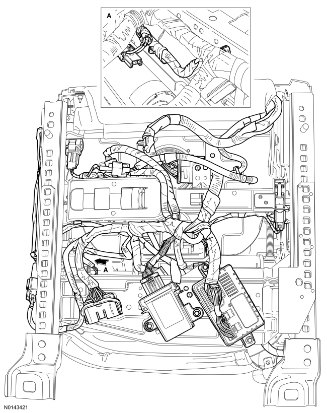
- Make sure the passenger seat cushion wire harness is correctly routed and attached.
 Diagnosis and Testing
Seating
Special Tool(s)
Medium Speed Controller Area Network (MS-CAN)
This vehicle utilizes a communication system called a Medium Speed Controller
Area Network (MS-CAN). When diagnosing the memory ...
 Removal and Installation
Seat - Front
NOTE: Refer to the installation steps for tightening sequence and
torque specification.
NOTE: Passenger seat shown, driver seat similar.
Removal
NOTE: The Supplemental R ...
Other materials:
Interior mirrors
WARNING: Do not adjust the mirror when your vehicle is
moving.
Note: Do not clean the housing or glass of any mirror with harsh
abrasives, fuel or other petroleum or ammonia based cleaning products.
You can adjust the interior mirror to your preference. Some mirrors also
have a second pivot p ...
General Procedures
Audio Control Module (ACM) Self-Diagnostic Mode
NOTE: If the ACM is completely inoperative (does not power up), the
part number decal on the ACM chassis can be used to attain the ACM part number.
Turn the ACM on.
Operate the audio system in radio tu ...
MyFord™ system
WARNING: Driving while distracted can result in loss of vehicle
control, crash and injury. We strongly recommend that you use
extreme caution when using any device that may take your focus off
the road. Your primary responsibility is the safe operation of your
vehicle. We recommend against the ...
