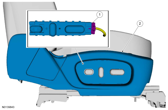
Seat - Front
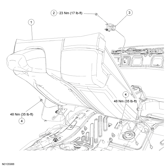
NOTE: Refer to the installation steps for tightening sequence and torque specification.
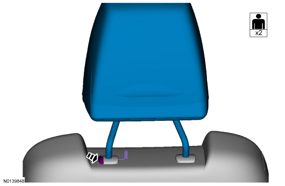
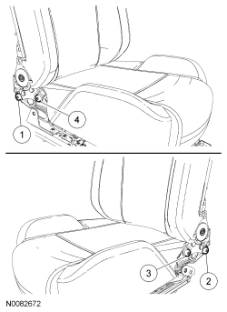
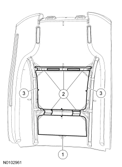
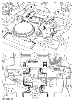
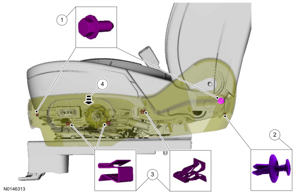
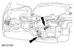
NOTE: Passenger seat shown, driver seat similar.
Removal
NOTE: The Supplemental Restraint System (SRS) must be fully operational and free of faults before releasing the vehicle to the customer.
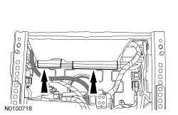
NOTE: If the seat rear mounting bolts are not accessible, refer to Accessing Mounting Bolts On an Inoperative Power Seat.
- WARNING:
Turn the ignition OFF and wait one minute to deplete the backup power
supply. Failure to follow this instruction may result in serious personal
injury or death in the event of an accidental deployment.
Turn the ignition OFF and wait at least one minute.
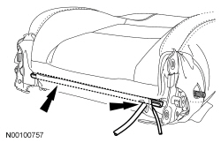
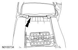
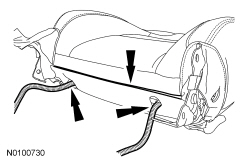
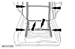
- Position the seat all the way forward and down.
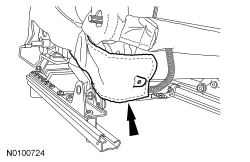
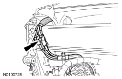
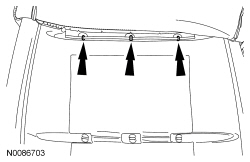
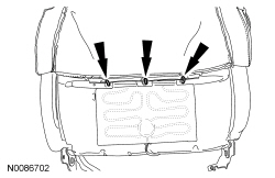
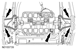
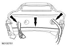
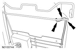
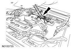
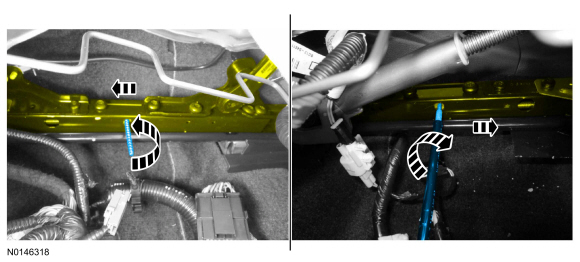
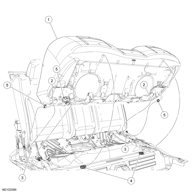
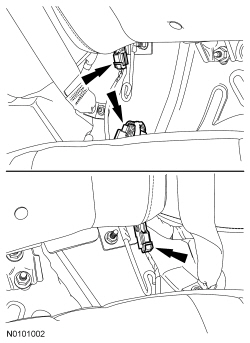
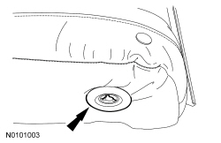
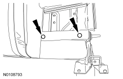
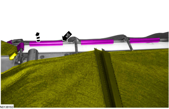
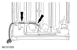
- Pull the inboard and outboard rear covers rearward and remove.
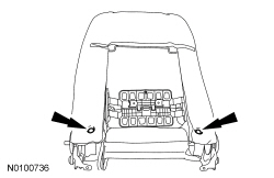
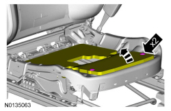
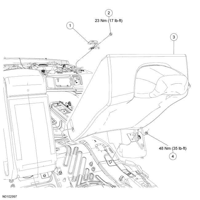
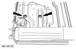
- Remove the 2 rear mounting bolts.
- Position the front seat.
- Position the seat to the middle of the track.
- Position the seat all the way up.
- Depower the SRS. Refer to Depowering and Repowering in the General Procedures Section 501-20B.
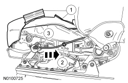
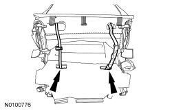
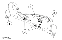
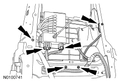
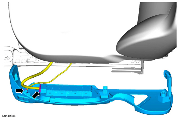
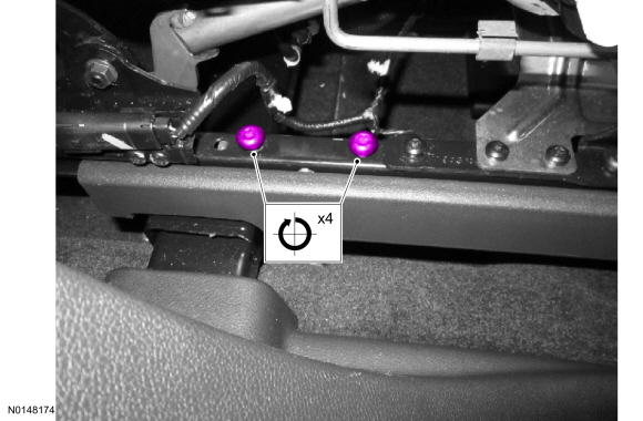
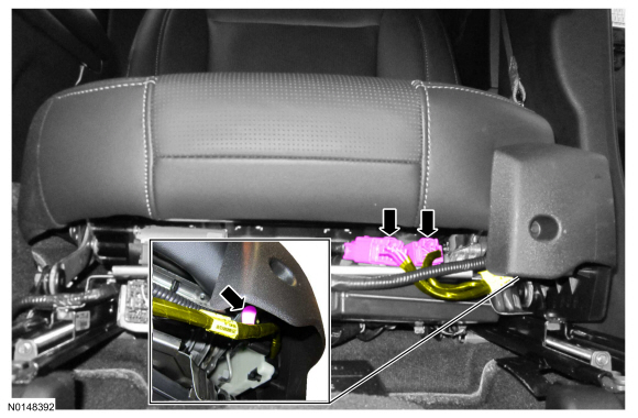
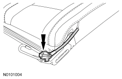
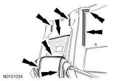
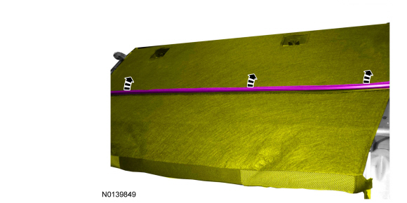
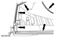
- Pull the inboard and outboard front covers forward and remove.
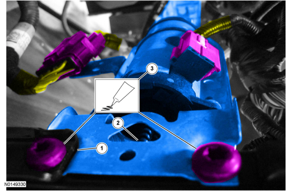
- Remove the 2 front mounting bolts.
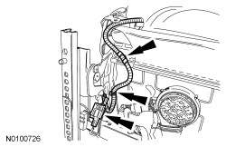
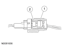
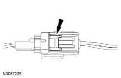
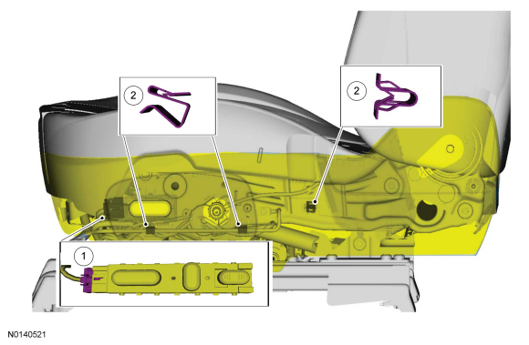
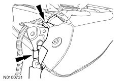
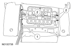
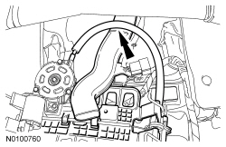
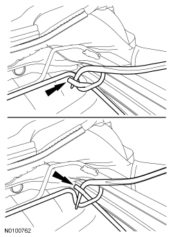
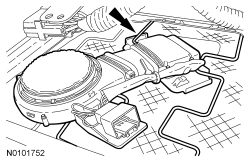
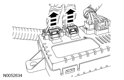
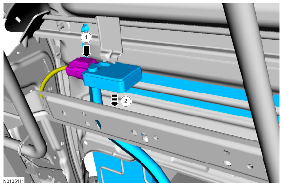
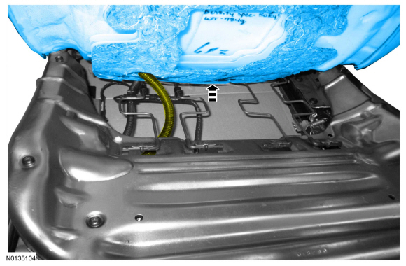
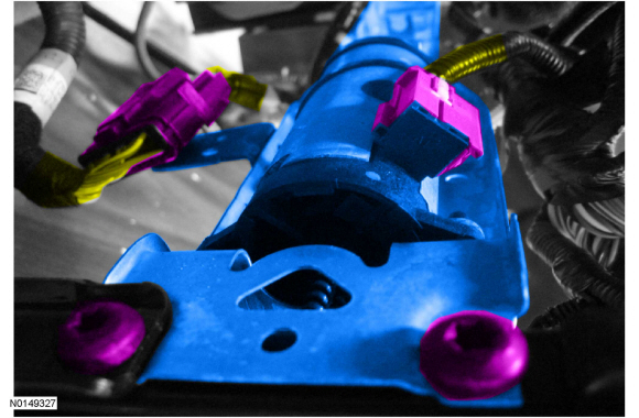
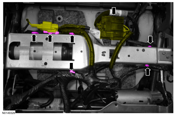
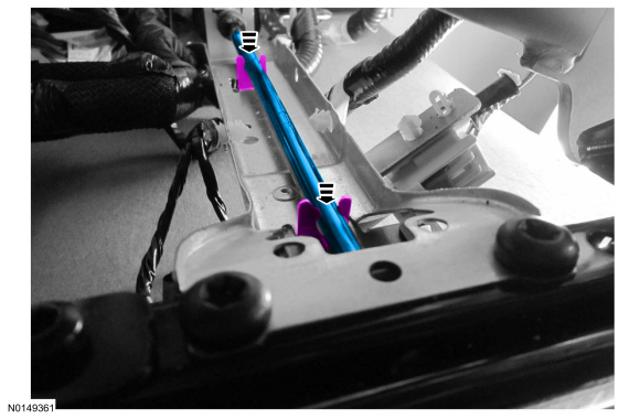
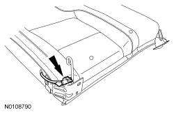
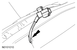
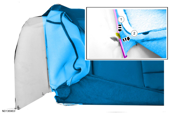
- Disconnect the seat electrical connector(s) and detach the wire harness
pin-type retainer.
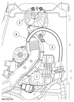
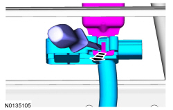
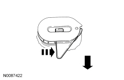
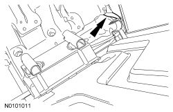
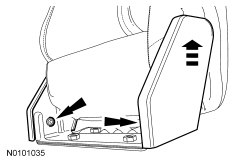
- Release the lever lock and pivot the lever back.
- WARNING:
Use care when handling the front passenger seat and track assembly. Dropping
the assembly, placing excessive weight on or sitting on a front passenger
seat that is not secured in the vehicle may result in damaged seat
components. Failure to follow these instructions may result in incorrect
operation of the occupant classification system (OCS) and increases the risk
of serious personal injury or death in a crash.
NOTICE: Use care when handling the driver seat and track assembly. Dropping the assembly or sitting on a seat not secured in the vehicle may result in damaged components.
Remove the front seat.
Installation
WARNING: Make sure the front passenger seat is correctly installed and fastened to the vehicle. Do not force the alignment to the floorpan mounting holes. If the seat does not align to the floorpan mounting holes, repair the seat or floorpan as needed. Failure to follow these instructions may result in incorrect operation of the occupant classification system (OCS) and increase the risk of serious personal injury or death in a crash.
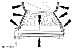
NOTE: Follow the installation procedure for correct seat fastener tightening sequence. The front mounting bolts must be installed and tightened to the correct specification before the rear mounting bolts.
All seats
- Position the seat in the vehicle.
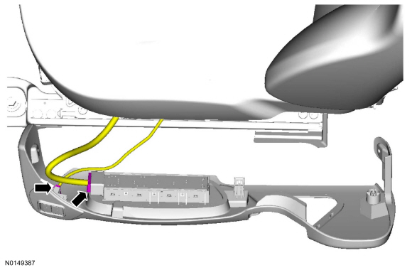
- Connect the seat electrical connector(s) and attach the wire harness pin-type retainer.
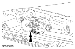
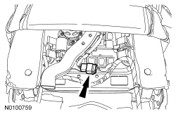
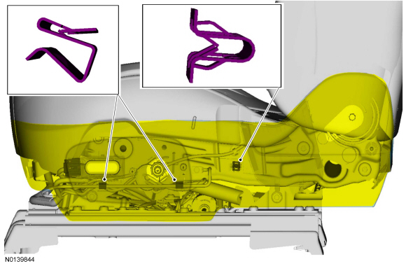
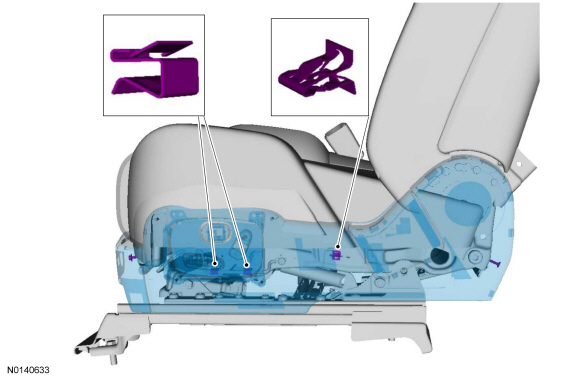
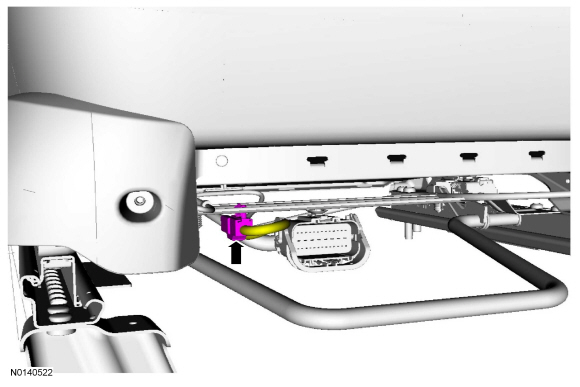
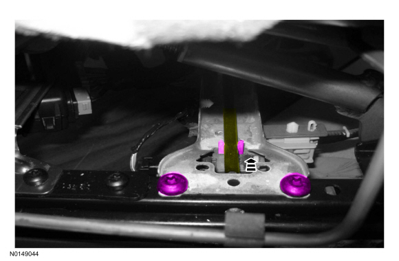
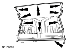
- Insert the 2 seat track rear locator pins into the Side Protection and Cabin Enhancement (SPACE) tube.
- WARNING:
Make sure no one is in the vehicle and there is nothing blocking or placed
in front of any airbag when the battery is connected. Failure to follow
these instructions may result in serious personal injury in the event of an
accidental deployment.
Connect the battery ground cable. Refer to Section 414-01
- Position the seat all the way rearward.
- Install the 2 front mounting bolts.
- Tighten to 48 Nm (35 lb-ft).
- Install the inboard and outboard front covers.
- Position the seat all the way forward and down.
- Disconnect the battery ground cable. Refer to Section 414-01.
- Install the 2 rear mounting bolts.
- Tighten to 48 Nm (35 lb-ft).
- Install the inboard and outboard rear covers.
- Repower the SRS. If a passenger seat with an OCS weight sensor bolt system (with Active Motion massage) has been serviced, do not prove out the SRS at this time. Refer to Supplemental Restraint System (SRS) Depowering and Repowering in the General Procedures portion of Section 501-20B.
Passenger seat with Active Motion massage
- Carry out the Occupant Classification System (OCS) System Reset. Refer to Section 501-20B.
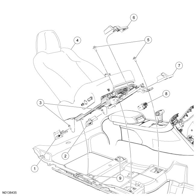
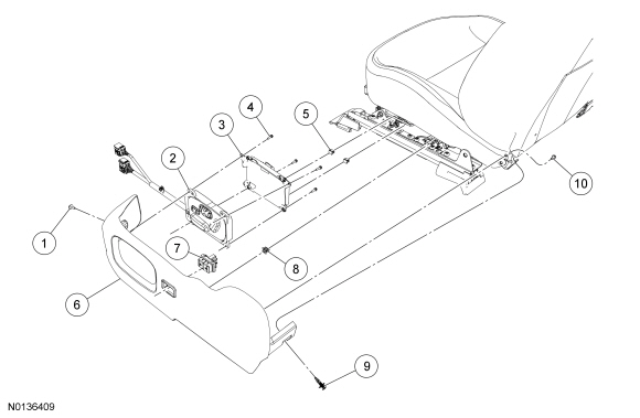
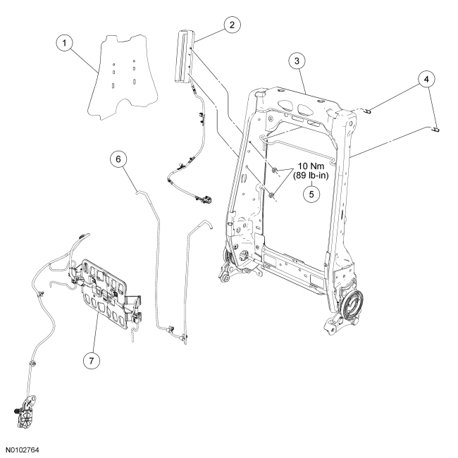
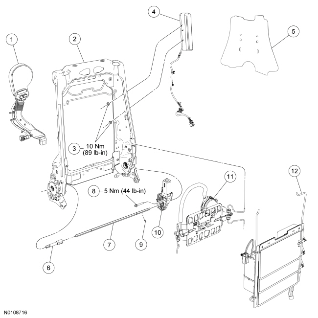
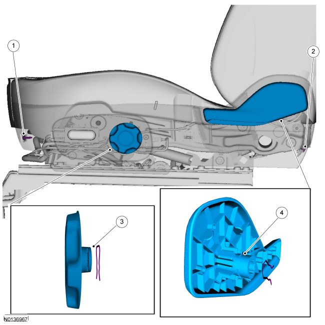
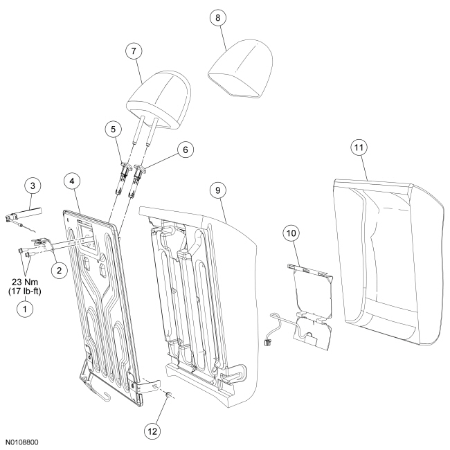
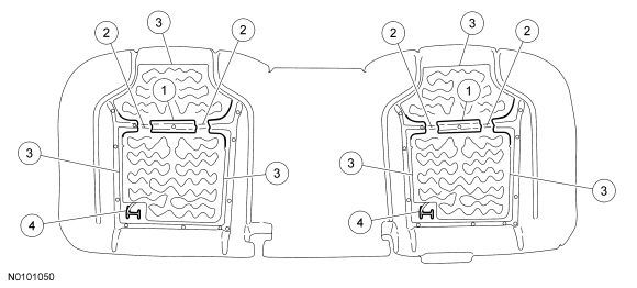
Seat - Exploded View, Front
Cushion Side Shield - Manual Seat Track With Manual Recline
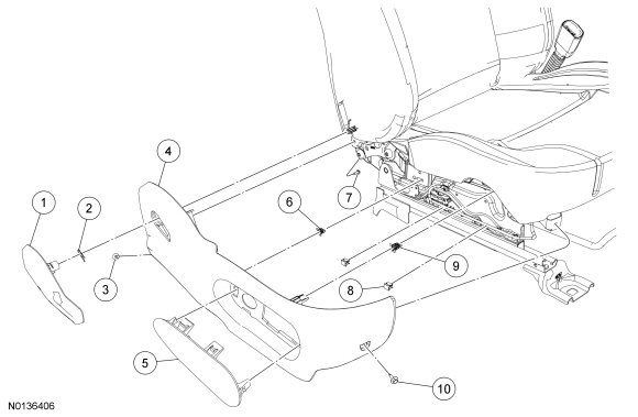
Cushion Side Shield - Power Seat Track With Manual Recline and Manual Lumbar
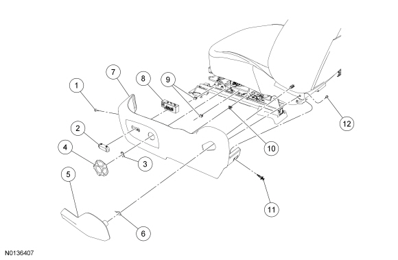
Cushion Side Shield - Power Seat Track With Power Recline, Power Lumbar and Memory
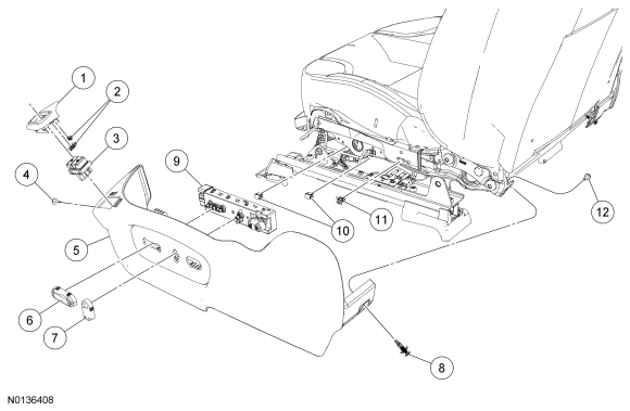
Cushion Side Shield - With Active Motion
Seat Backrest - Trim Components
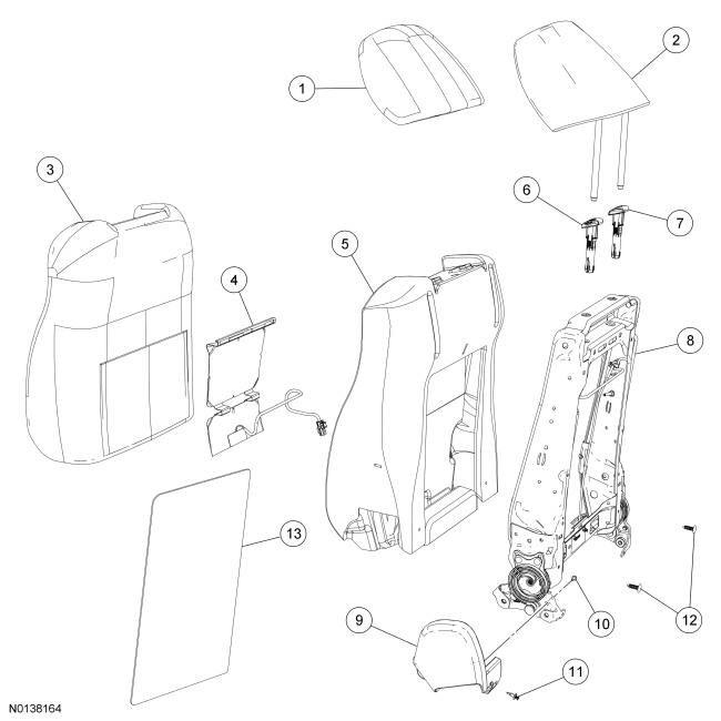
Seat Backrest - Frame Components With Manual Lumbar or Static Lumbar
Seat Backrest - Frame Components With Power Lumbar
Seat Cushion - With Active Motion
NOTE: Refer to Seat Backrest - Front for recliner-to-seat track bolt tightening sequence and torque specification.
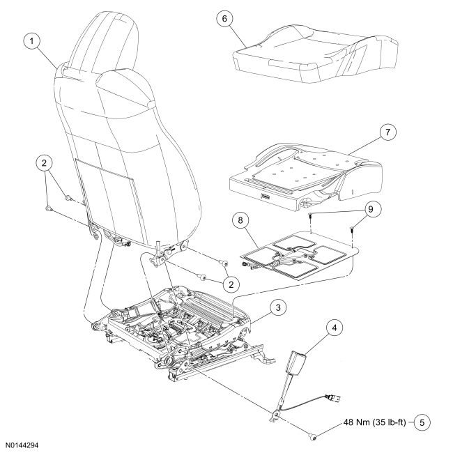
Seat Cushion - Without Active Motion
NOTE: Refer to Seat Backrest - Front for recliner-to-seat track bolt tightening sequence and torque specification.
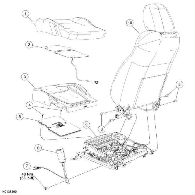
Passenger Power Seat Track
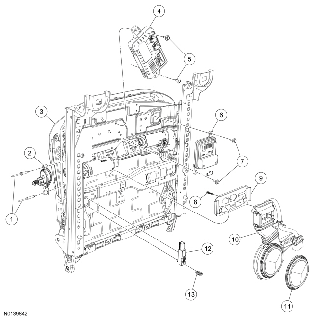
Driver Power Seat Track
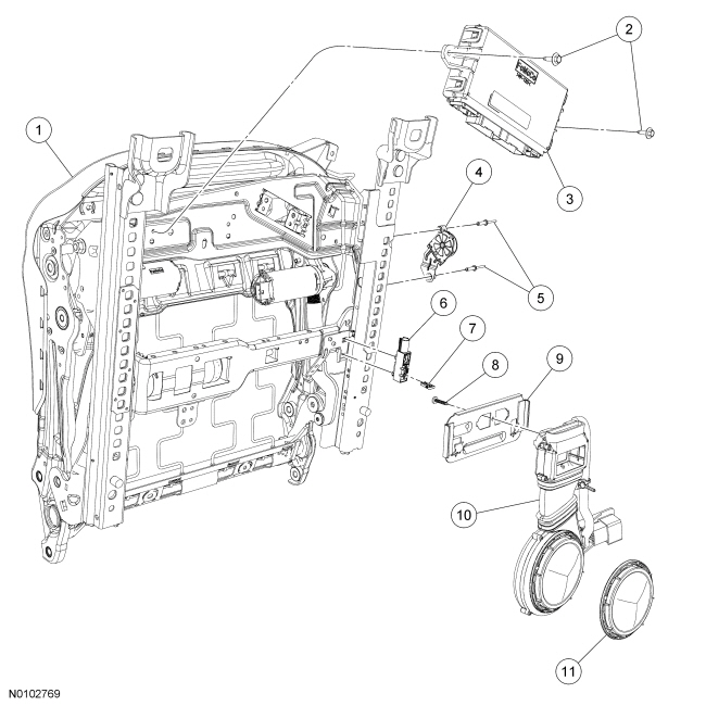
- For additional information, refer to the procedures in this section.
Head Restraint Guide Sleeve - Front
General Equipment
- Paper Clip
Removal
Vehicles without police package
- Push both of the head restraint guide sleeve release buttons and remove the head restraint.
Vehicles with police package
- Insert the straightened end of a paper clip into the inboard guide
sleeve hole while pressing the guide sleeve release button and remove the
head restraint.
General Equipment: Paper Clip.
All vehicles
- Obtain a flat-head screwdriver with a tip width of 4 mm (0.16 in) - 7 mm (0.28 in) and a thickness of approximately 1 mm (0.04 in).
- Push the backrest cover and foam pad down and insert the screwdriver between the head restraint guide sleeve neck and backrest trim cover and foam pad, at the middle of the head restraint guide sleeve release button.
- Remove the head restraint guide sleeve in the following sequence:
- Using the screwdriver, press the head restraint guide sleeve retaining tab inward approximately 5 mm (0.2 in).
- While pressing the head restraint guide sleeve retaining tab inward, pull upward on the head restraint guide sleeve and remove it from the backrest frame crossmember.
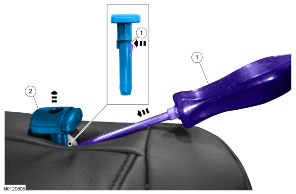
- Discard the head restraint guide sleeve.
Installation
NOTICE: Always install new head restraint guide sleeves. Reusing old head restraint guide sleeves may result in head restraint rattles.
NOTICE: Front seats only: The head restraint guide sleeves are not interchangeable. Failure to install the head restraint guide sleeves into the correct locations may result in the inability to adjust the head restraint.
- Make sure the holes in the backrest foam pad and backrest trim cover are aligned to the holes in the backrest frame.
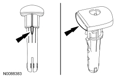
- For front seats, install the head restraint guide sleeve with the wide key and large button on the LH side of the seat.
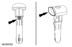
- For front seats, install the head restraint guide sleeve with the thin key and small button on the RH side and at all locations for the rear seats.
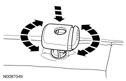
- NOTICE: To allow the head restraint guide sleeve to slide
freely through the backrest foam pad and backrest trim cover, twist the head
restraint guide sleeve while pushing it into the backrest frame hole as far
as it will go, using hand pressure.
By hand, press the head restraint guide sleeve downward into the backrest frame hole.
- Inspect the head restraint guide sleeve.
- By hand, pull upward on the head restraint guide sleeve and make sure it is correctly locked into the backrest frame hole. If the head restraint guide sleeve can be removed by hand, repeat the installation procedure. If the head restraint guide sleeve can be removed again after installing a second time, install a new head restraint guide sleeve.
- Repeat these steps for the head restraint guide sleeve on the opposite side.
- After installing the new head restraint guide sleeves, install the head
restraint in the following sequence:
- Position the head restraint rods to the head restraint guide sleeve holes.
- Guiding the head restraint rods into the head restraint guide sleeve holes, push the head restraint downward until it locks in place.
- NOTE: The rear head restraints are not adjustable.
Verify that the front head restraints can be adjusted without excessive effort.
Seat Backrest - Front
Removal
NOTE: For component identification and locations, refer to Seat - Exploded View, Front.
- Remove the seat. Refer to Seat - Front.
- Detach the carpet flap toe-kick retainers from under the seat.

- Remove the recliner cover.
- Remove the screw.
- Remove the scrivet.
- Lift and release the hook.
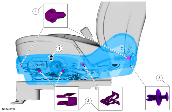
- Remove the side shield retainers and manual lumbar and recline handles
(if equipped).
- Remove the screw.
- Remove the scrivet.
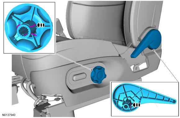
- Remove the clip and the lumbar handle (if equipped).
- Remove the clip and the recliner handle (if equipped).

- If equipped with a lumbar Active Motion massage adjuster, disconnect the seat control switch electrical connectors and wire harness from the front of the seat.
- If equipped with a manual seat, remove the cushion side shield cover and
the cushion side shield screw.
- Remove the cushion side shield cover.
- Remove the cushion side shield cover screw.

- Release the cushion side shield retainers from the seat cushion.

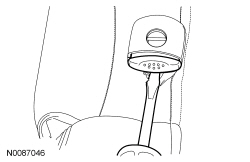
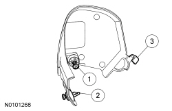
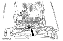
- NOTE: Other seat control switches similar to switch shown.
Remove the cushion side shield from the seat cushion.
- If equipped, disconnect the wire harness connector from the seat control switch.

- Detach the cushion cover from the recliner cover.
- If equipped, separate the manual lumbar cable cover.
- Detach the cushion cover outboard J-clips and position the cushion cover flap up.
- Separate the cable retainer.
- Pull the cable cover out of the adjuster.
- If equipped, remove the manual lumbar cable from the adjuster.
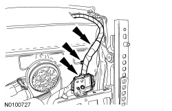
- NOTE: Wire harness routing for installation.
Release the side air bag module electrical connector and wire harness retainers under the seat.
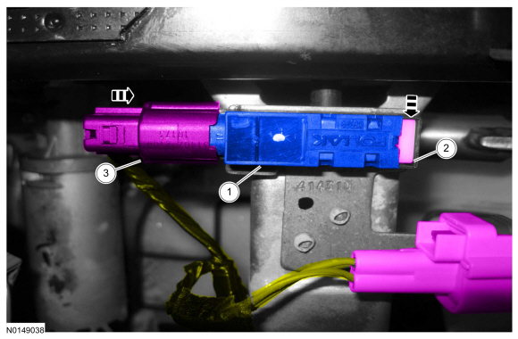
- Disconnect the side air bag module electrical connector.
- Slide the locking clip back.
- Push the tab in and disconnect the electrical connector.
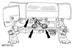
- NOTE: Wire harness routing for installation.
If equipped, disconnect the backrest electrical connector and release the wire harness retainers under the seat.

- If equipped, separate the lumbar Active Motion massage adjuster
assembly hoses.
- Push the 4 release buttons and disconnect the 4 hoses.
- WARNING:
Use care when the seat back frame is removed and when releasing the
recliners from a backrest upright position. The recliners are spring-loaded,
which may cause the recliner upper arms to fold with significant
speed/force. Failure to follow this instruction may result in serious
personal injury.
Remove the 4 recliner-to-seat track bolts and remove the backrest assembly.
- Route the wire harness(es) and air hoses (if equipped) out of the hole(s) in the carpet flap toe-kick.
Installation
All seats
- If equipped, route the wire harness(es) and air hoses through the hole(s) in the carpet flap toe-kick.
- Position the backrest assembly to the seat track and manually tighten
the 4 recliner-to-seat track bolts by hand.
- If equipped, route the manual lumbar cable between the backrest and cushion and to the inside of the recliner.
Driver seat
- Tighten the 4 recliner-to-seat track bolts.
- Tighten the rear outboard bolt to 48 Nm (35 lb-ft).
- Tighten the rear inboard bolt to 48 Nm (35 lb-ft).
- Tighten the front inboard bolt to 48 Nm (35 lb-ft).
- Tighten the front outboard bolt to 48 Nm (35 lb-ft).
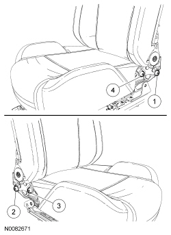
Passenger seat
- Tighten the 4 recliner-to-seat track bolts.
- Tighten the rear outboard bolt to 48 Nm (35 lb-ft).
- Tighten the rear inboard bolt to 48 Nm (35 lb-ft).
- Tighten the front inboard bolt to 48 Nm (35 lb-ft).
- Tighten the front outboard bolt to 48 Nm (35 lb-ft).
All seats
- If equipped, match the lumbar Active Motion massage adjuster assembly color-coded hoses and connect together.
- If equipped, connect the backrest electrical connector and attach the wire harness retainers under the seat.
- Connect the side air bag module electrical connector and slide the locking clip to the lock position.
- Attach the side air bag module electrical connector and wire harness retainers under the seat.
- If equipped, install the manual lumbar cable in the following sequence.
- Position the manual lumbar cable into the adjuster.
- Position the manual lumbar cable cover into the adjuster.
- Install the manual lumbar cable retainer.
- Position the cushion cover flap back around the side of the seat and attach the outboard J-clips.
- Attach the cushion cover around the recliner.

- NOTE: Other seat control switches similar to switch shown.
Align the cushion side shield to the cushion.
- If equipped, connect the seat control switch to the seat wire harness connector.
- Align and engage the cushion side shield retainers to the cushion.
- Install the cushion side shield to the seat.
- Install the screw at the front of the cushion side shield.
- Install the pushpin located at the rear of the cushion side shield.
- If equipped, attach the manual recline handle and clip.
- If equipped, attach the manual lumbar handle and clip.
- If equipped with a manual seat, install the cushion side shield cover
and the cushion side shield screw.
- Install cushion side shield cover screw.
- Attach the cushion side shield cover.
- Install the recliner cover in the following sequence.
- Attach the hook at the front of the recliner cover.
- Install the screw.
- Install the scrivet.

- Attach the carpet flap toe-kick retainers under the seat.

- Install the seat. If a passenger seat with an OCS bladder system (without Active Motion massage) has been serviced, do not prove out the SRS within the seat installation procedure. Refer to Seat - Front.
Passenger seat without Active Motion massage
- Carry out the Occupant Classification System (OCS) Reset. Refer Section 501-20B.
Seat Backrest Cover - Front
Removal
WARNING: Front seat backrest trim covers installed on seats equipped with seat side airbags cannot be repaired. A new trim cover must be installed. Cleaning is permissible. Failure to follow these instructions may result in the seat side airbag deploying incorrectly and increase the risk of serious personal injury or death in a crash.
NOTE: If a side air bag deployment occurs, a new seat backrest foam pad, backrest cover, deployment chute and side air bag module and nuts must be installed. A new seat backrest frame should be installed, if necessary.
NOTE: For component identification and locations, refer to Seat - Exploded View, Front.
- Remove the seat backrest. Refer to Seat Backrest - Front.
- Remove the 2 head restraint guides sleeves. Refer to Head Restraint Guide Sleeve - Front.
- NOTE: Note wire harness and hose routing for installation.
Detach the backrest cover lower J-clip and route the wire harness(es) and air hoses (if equipped) out of the hole(s) in the backrest cover.

- On each side, separate the backrest cover clip and hook-and-loop strips.

- If equipped with police package, access the stab shield.
- Release seat backrest seat cover J-clip.
- Release hook-and-loop strip to the stab shield pocket cover.
- Open the backrest stab shield pocket cover to release the stab shield.
- If equipped with police package, remove the stab shield from the backrest stab shield pocket.
- NOTICE: Use care when separating the backrest cover from the
hook-and-loop strip, or the hook-and-loop strip can be torn from the
backrest foam pad.
Separate the hook-and-loop strips, invert the backrest cover up and remove the 3 first row hog rings.

- Separate the hook-and-loop strips, invert the backrest cover up and remove the 3 second row hog rings.
- From the rear of the backrest, detach the backrest cover J-clip attached to the backrest frame wire.

- Invert the backrest cover up, separate the hook-and-loop strips and remove the backrest cover.
Installation
- WARNING:
If the seat side air bag module deployment chute is not correctly
positioned, the seat side air bag may not deploy correctly. Failure to
follow this instruction may result in the seat side air bag deploying
incorrectly, which increases the risk of serious personal injury or death in
a crash.
WARNING: Inspect the seat side air bag module cavity in the seat backrest foam pad for any foreign material. If any foreign material is found, remove it. Failure to follow these instructions may result in the seat side air bag module deploying incorrectly and increases the risk of serious personal injury or death in a crash.
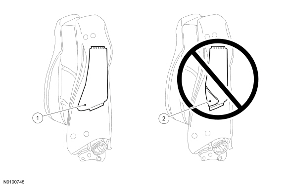
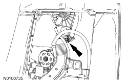
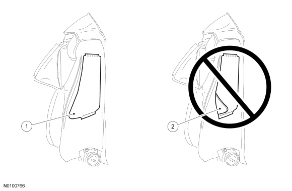
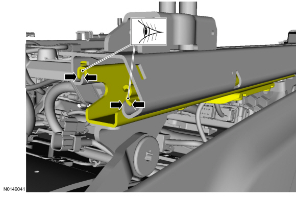
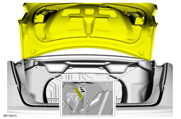
NOTE: The seat side air bag module must have a clear exit path from the front of the deployment chute. Both deployment chute front edges must be positioned to lay flat when positioned between the backrest foam pad and backrest frame.
NOTE: Illustration shown looking through the side of the backrest foam pad and at the side air bag module deployment chute.
Check the position of the deployment chute.- Position both deployment chute front edges to lay flat, from top to bottom, between the backrest foam pad and backrest frame.
- Do not allow the deployment chute front edges to fold over at any point between the backrest foam pad and backrest frame.
- With the backrest cover inside out, position it to the backrest foam pad
and frame assembly.
- Align the head restraint holes in the backrest cover to the holes in the backrest foam pad and frame.
- Roll the backrest cover down, attach the hook-and-loop strips and engage the J-clip at the rear to the backrest frame wire.
- Roll the backrest cover down, attach the hook-and-loop strips and
install the 3 second row hog rings.
- If equipped with heated seats, make sure the backrest heater mat windows are trapped between the backrest cover wire and backrest foam pad wire.
- Roll the backrest cover down, attach the hook-and-loop strips and
install the 3 first row hog rings.
- If equipped with heated seats, make sure the backrest heater mat windows are trapped between the backrest cover wire and backrest foam pad wire.
- If equipped with police package, install the stab shield
- Insert the stab shield into the seat backrest stab shield pocket opening.
- Attach the stab shield pocket opening cover hook-and-loop strips.
- Roll the backrest cover down and attach the hook-and-loop strips.
- Route the wire harness(es) and air hoses (if equipped) through the
hole(s) in the backrest cover.
- Make sure the manual lumbar cable is routed out from the outboard side of the backrest before engaging the lower J-clip (if equipped).
- Engage the seat backrest lower J-clip.
- On each side, wrap the backrest cover around the recliner and attach the hook-and-loop strips and clip.
- Install the 2 head restraint guides sleeves. Refer to Head Restraint Guide Sleeve - Front.
- Install the seat backrest. Refer to Seat Backrest - Front.
Seat Backrest Heater Mat - Front
Removal
NOTICE: The heater mat is not designed to be separated from the foam pad. Doing so will damage the foam pad. Install a new foam pad and heater mat. Failure to follow this instruction can result in seat component damage and system failure.
NOTE: For parts identification and location, refer to Seat - Exploded View, Front in this section.
- Remove the seat backrest cover. For additional information, refer to Seat Backrest Cover - Front in this section.
- Disconnect the backrest heater mat electrical connector and separate the pin-type retainer.
- Remove 2 pin-type retainers.

- Remove the backrest foam pad from the backrest frame. Discard the
backrest foam pad with heater mat.
- Do not remove the old backrest heater mat from the old backrest foam pad and reuse any of these parts.
Installation
- Install a new backrest heater mat onto a new backrest foam pad.
- Position the heater mat wire harness through the backrest foam pad.
- Position the backrest heater mat onto the backrest foam pad and tuck
the heater mat into the foam pad trenches.
- Make sure the openings in the backrest heater mat align to the wires in the backrest foam pad.
- Make sure the backrest heater mat stays in place, remove the paper strips from under the backrest heater mat and adhere to the backrest foam pad, laying it flat with no wrinkles.
- WARNING:
Inspect the seat side air bag module cavity in the seat backrest foam pad
for any foreign material. If any foreign material is found, remove it.
Failure to follow these instructions may result in the seat side air bag
module deploying incorrectly and increases the risk of serious personal
injury or death in a crash.
Position the backrest frame assembly into the backrest foam pad. Install the 2 pin-type retainers.
- Connect the backrest heater mat electrical connector and attach the pin-type retainer.
- Install the seat backrest cover. For additional information, refer to Seat Backrest Cover - Front in this section.
Seat Backrest Thermo-Electric Device
Removal
NOTE: For parts identification and location, refer to Seat - Exploded View, Front in this section.
- Remove the seat backrest. For additional information, refer to Seat Backrest - Front in this section.
- NOTE: Note wire harness routing for installation.
Disengage the backrest cover lower J-clips and route the wire harness(es) and air hoses (if equipped) out of the hole(s) in the backrest cover.

- On each side, separate the backrest cover clip and hook-and-loop strips.
- NOTICE: Use care when separating the backrest cover from the
hook-and-loop strip, or the hook-and-loop strip can be torn from the
backrest foam pad.
Separate the hook-and-loop strips, invert the backrest cover up and remove the 3 first row hog rings.
- Separate the hook-and-loop strips, invert the backrest cover up and remove the 3 second row hog rings.

- From the rear of the backrest, disengage the backrest cover J-clip attached to the backrest frame wire.

- Invert the backrest cover up enough to access the backrest Thermo-Electric Device (TED) upper retainers.
- Remove the backrest TED.
- Disconnect the electrical connector and separate the pin-type retainer.
- Disengage the TED from the backrest frame wire.
- Disengage the backrest TED from the backrest foam pad wire.
- Slide the TED out from between the power lumbar and cable.
Installation
- Install the backrest TED.
- Position the TED through the power lumbar cable.
- Attach the TED to the backrest foam pad wire.
- Engage the TED upper retainers to the backrest frame wire.
- Connect the electrical connector and attach the pin-type retainer.
- Roll the backrest cover down, attach the hook-and-loop strips and engage the J-clip at the rear to the backrest frame wire.
- Roll the backrest cover down, attach the hook-and-loop strips and install the 3 second row hog rings.
- Roll the backrest cover down, attach the hook-and-loop strips and install the 3 first row hog rings.
- Roll the backrest cover down and attach the hook-and-loop strips.
- Route the wire harness(es) and air hoses (if equipped) through the hole(s) in the backrest cover and engage the lower J-clips.
- On each side, wrap the backrest cover around the recliner and attach the hook-and-loop strips and clip.
- Install the seat backrest. For additional information, refer to Seat Backrest - Front in this section.
Lumbar Assembly - Manual
Removal
NOTE: For parts identification and location, refer to Seat - Exploded View, Front in this section.
- Remove the backrest. For additional information, refer to Seat Backrest - Front in this section.
- NOTE: Note wire harness routing for installation.
Disengage the backrest cover lower J-clips and route the wire harness out of the hole in the backrest cover.
- On each side, separate the backrest cover clip and hook-and-loop strips.

- NOTICE: Use care when separating the backrest cover from the
hook-and-loop strip, or the hook-and-loop strip can be torn from the
backrest foam pad.
Separate the hook-and-loop strips and invert the backrest cover up to the first backrest cover wire.
- Remove the manual lumbar.
- Disengage the cable.
- Disengage the manual lumbar retainers.
- NOTICE: Do not let metal shavings get into the seat track.
Failure to follow this instruction can result in seat track damage and
failure.
Remove the rivets and the manual lumbar control.
Installation
- Position the manual lumbar control and install new rivets.
- Engage the manual lumbar retaining clips and cable retainer.
- Roll the backrest cover down and attach the hook-and-loop strips.
- Route the wire harness through the hole in the backrest cover and engage
the lower J-clips.
- Make sure the manual lumbar cable is routed out from the outboard side of the backrest cover before engaging the lower J-clips.

- On each side, wrap the backrest cover around the recliner and attach the hook-and-loop strips and clip.

- Install the seat backrest. For additional information, refer to Seat Backrest - Front in this section.
Lumbar Assembly - Power
Removal
NOTE: For parts identification and location, refer to Seat - Exploded View, Front in this section.
- Remove the seat backrest. For additional information, refer to Seat Backrest - Front in this section.
- NOTE: Note wire harness routing for installation.
Disengage the backrest cover lower J-clips and route the wire harness(es) out of the hole(s) in the backrest cover.

- On each side, separate the backrest cover clip and hook-and-loop strips.

- NOTICE: Use care when separating the backrest cover from the
hook-and-loop strip, or the hook-and-loop strip can be torn from the
backrest foam pad.
Separate the hook-and-loop strips and invert the backrest cover up to the first row of hog rings.
- If equipped, disconnect the backrest Thermo-Electric Device (TED) electrical connector and disengage the pin-type retainer.
- Remove the power lumbar.
- Disconnect the motor and disengage the retaining clips.
Installation
- If equipped, position the TED duct between the power lumbar and cable.
- Engage the power lumbar retaining clips to the backrest frame and connect the motor.
- If equipped, connect the backrest TED electrical connector and engage the pin-type retainer.
- Roll the backrest cover down and attach the hook-and-loop strips.
- Route the wire harness(es) through the hole(s) in the backrest cover and engage the lower J-clips.
- On each side, wrap the backrest cover around the recliner and attach the hook-and-loop strips and clip.

- Install the seat backrest. For additional information, refer to Seat Backrest - Front in this section.
Active Motion Massage Adjuster
Removal and Installation
- Remove the seat. Refer to Seat - Front.
- From the front of the seat, detach the wire harness retainer and disconnect the seat control switch electrical connectors.

- NOTE: Note hose routing for correct installation.
Detach the carpet flap toe-kick retainers from under the seat.

- Remove the cushion side shield.
- Remove the scrivet at the back.
- Remove the screw at the front.
- Pull out at the side to release the retainers.
- Slide down and separate the hook.
- Disconnect the lumbar Active Motion massage adjuster hoses.
- Push the 4 release buttons to disconnect the 4 hoses.

- Detach the cushion cover J-clips at the front and outboard sides.
- Position the cushion foam pad away and detach the Active Motion adjuster pin-type retainers.

- Route the cushion Active Motion adjuster hoses through the cushion support wires and remove the assembly.

- To install, reverse the removal procedure.
Lumbar and Active Motion Massage Adjuster Assembly
Removal
NOTE: For parts identification and location, refer to Seat - Exploded View, Front.
- Remove the seat backrest. Refer to Seat Backrest - Front.
- NOTE: Note wire harness and hose routing for installation.
Disengage the backrest cover lower J-clips and route the wire harness(es) and air hoses out of the hole(s) in the backrest cover.
- On each side, separate the backrest cover clip and hook-and-loop strips.

- NOTICE: Use care when separating the backrest cover from the
hook-and-loop strip, or the hook-and-loop strip can be torn from the
backrest foam pad.
Separate the hook-and-loop strips, invert the backrest cover up and remove the 3 first row hog rings.

- Separate the hook-and-loop strips, invert the backrest cover up and remove the 3 second row hog rings.

- From the rear of the backrest, disengage the backrest cover J-clip attached to the backrest frame wire.
- Remove the 2 pin-type retainers at the rear of the backrest foam pad.

- Pry the upper retainers around the backrest frame wire.
- Disconnect the electrical connectors, detach the pin-type retainers, disengage the lower retainers and remove the assembly.
Installation
- Install the lower retainers, connect the electrical connectors and attach the pin-type retainers.
- Pry both upper retainers around the backrest frame wire.
- Install the 2 pin-type retainers at the rear of the backrest foam pad.
- Roll the backrest cover down, attach the hook-and-loop strips and engage the J-clip at the rear to the backrest frame wire.
- Roll the backrest cover down, attach the hook-and-loop strips and install the 3 second row hog rings.
- Roll the backrest cover down, attach the hook-and-loop strips and install the 3 first row hog rings.
- Roll the backrest cover down and attach the hook-and-loop strips.
- Route the wire harness(es) and air hoses through the hole(s) in the backrest cover and engage the lower J-clips.
- On each side, wrap the backrest cover around the recliner and attach the hook-and-loop strips and clip.
- Install the seat backrest. Refer to Seat Backrest - Front.
Seat Recliner Motor
Removal
NOTE: For component identification and locations, refer to Seat - Exploded View, Front in this section.
- Remove the seat backrest. For additional information, refer to Seat Backrest - Front in this section.
- NOTE: Note wire harness and hose routing for installation.
Disengage the backrest cover lower J-clips and route the wire harness(es) and air hoses (if equipped) out of the hole(s) in the backrest cover.
- On each side, separate the backrest cover clip and hook-and-loop strips.

- NOTICE: Use care when separating the backrest cover from the
hook-and-loop strip, or the hook-and-loop strip can be torn from the
backrest foam pad.
Separate the hook-and-loop strips, invert the backrest cover up and remove the 3 first row hog rings.

- Separate the hook-and-loop strips, invert the backrest cover up and remove the 3 second row hog rings.

- From the rear of the backrest, disengage the backrest cover J-clip attached to the backrest frame wire.

- If equipped, separate the backrest Thermo-Electric Device (TED) from the backrest foam pad wire.
- Remove the 2 pin-type retainers at the rear of the backrest foam pad.
- NOTICE: Do not rotate the inboard and outboard recliners
separately from each other. Doing so will cause the recliners to become out
of synchronization.
Remove the E-clip on the recliner shaft and the recliner motor bolt.
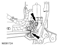
- Remove the power recliner motor.
- Slide the recliner shaft assembly out of the recliner and remove the short recliner shaft.
- Slide the long recliner shaft out of the recliner motor.
- Disconnect and remove the power recliner motor.
Installation
- NOTICE: Do not rotate the inboard and outboard recliners
separately from each other. Doing so will cause the recliners to become out
of synchronization.
Install the recliner motor in the following sequence.
- Slide the long recliner shaft into the recliner motor and recliner.
- Connect the recliner motor.
- Slide the short recliner shaft onto the long recliner shaft.
- Slide the recliner shaft assembly into the recliner on the other side.
- Position the recliner motor and install the bolt.
- Tighten to 5 Nm (44 lb-in).
- Install the E-clip on the recliner shaft recession, near the recliner motor.
- Install 2 pin-type retainers at the rear of the backrest foam pad.
- If equipped, attach the backrest TED to the backrest foam pad wire.
- WARNING:
If the seat side air bag module deployment chute is not correctly
positioned, the seat side air bag may not deploy correctly. Failure to
follow this instruction may result in the seat side air bag deploying
incorrectly, which increases the risk of serious personal injury or death in
a crash.
WARNING: Inspect the seat side air bag module cavity in the seat backrest foam pad for any foreign material. If any foreign material is found, remove it. Failure to follow these instructions may result in the seat side air bag module deploying incorrectly and increases the risk of serious personal injury or death in a crash.
NOTE: The seat side air bag module must have a clear exit path from the front of the deployment chute. Both deployment chute front edges must be positioned to lay flat when positioned between the backrest foam pad and backrest frame.
NOTE: Illustration shown looking through the side of the backrest foam pad and at the side air bag module deployment chute.
Check the position of the deployment chute.- Position both deployment chute front edges to lay flat, from top to bottom, between the backrest foam pad and backrest frame.
- Do not allow the deployment chute front edges to fold over, at any point, between the backrest foam pad and backrest frame.
- Roll the backrest cover down, attach the hook-and-loop strips and engage the J-clip at the rear to the backrest frame wire.
- Roll the backrest cover down, attach the hook-and-loop strips and install the 3 second row hog rings.
- Roll the backrest cover down, attach the hook-and-loop strips and install the 3 first row hog rings.
- Roll the backrest cover down and attach the hook-and-loop strips.
- Route the wire harness(es) through the hole(s) in the backrest cover and engage the lower J-clips.

- On each side, wrap the backrest cover around the recliner and attach the hook-and-loop strips and clip.
- Install the seat backrest. For additional information, refer to Seat Backrest - Front in this section.
- If a new seat recliner motor has been installed on a driver seat with memory, operate the seat in all directions through the full range of travel to set soft stops and avoid a premature stopping point occurrence after the vehicle is returned to the customer.
Seat Cushion Cover - Front
Special Tool(s)
Removal
NOTICE: If the passenger seat is equipped with an Occupant Classification Sensor (OCS) bladder system, to prevent system failure, it is necessary to carry out the OCS system reset when a front passenger seat cushion is disassembled, a new cushion cover is installed or an OCS system service kit is installed. A scan tool is used to carry out the OCS system reset.
NOTE: For component identification and locations, refer to Seat - Exploded View, Front in this section.
- Remove the front seat backrest. For additional information, refer to Seat Backrest - Front in this section.
- Disengage the cushion cover retainers from the cushion frame and seat track.
- NOTICE: Use care when separating the cushion cover wires from
the cushion foam pad clips or the clips can be torn from the cushion foam
pad.
Turn the cushion cover inside out, disengage the cushion cover wires from the retainers in the cushion foam pad and remove the cushion cover.
Installation
All seats
- Position the cushion cover and engage the wires into the retainers of
the cushion foam pad.
- If equipped with heated seats, make sure the cushion heater mat windows are trapped between the cushion cover wire and cushion foam pad retainers.
- Engage the cushion cover retainers to the cushion frame and seat track.
- Do not engage the outboard cushion cover retainers, if equipped with manual lumbar.
- NOTE: To identify the Occupant Classification Sensor (OCS)
system, refer to Seat - Exploded View, Front in this section.
Install the front seat backrest. If a passenger seat with a bladder OCS has been serviced, do not prove out the SRS within the seat installation procedure. Proceed to the next step here after the seat has been installed in the vehicle and repower has been done. For additional information, refer to Seat Backrest - Front in this section.
Passenger seat with a bladder OCS
- Carry out the Occupant Classification Sensor (OCS) System Reset. For additional information, refer to the General Procedures portion of Section 501-20B.
Seat Cushion Heater Mat - Front
Removal and Installation
NOTICE: Do not reinstall any heater mat after removal. The adhesive will not adhere correctly, causing it to bunch up or shift out of place. A new heater mat and new foam pad must be installed. If a new heater mat is needed for a passenger seat cushion, an Occupant Classification System (OCS) must be installed. Failure to follow these instructions can result in heated seat component damage, system failure or incorrect OCS operation.
NOTE: If the passenger seat is equipped with an Occupant Classification System (OCS) bladder system, a new OCS and a new cushion heated seat mat must be installed. Refer to Occupant Classification Sensor in Section 501-20B.
NOTE: Removal steps in this procedure may contain installation details.
NOTE: For component identification and locations, refer to Seat - Exploded View, Front.
All seats
- Remove the seat. Refer to Seat - Front.
Passenger seat without Active Motion massage
- Install a new OCS. Refer Section 501-20B.
All seats except passenger seat without Active Motion massage
- Remove the seat cushion cover. Refer to Seat Cushion Cover - Front.
- NOTE: Note wire harness routing for installation.
Disconnect the heater mat electrical connector.
- Remove the cushion foam pad from the cushion frame. Discard the cushion foam pad with heater mat.
- To install, reverse the removal procedure.
- Install a new cushion heater mat onto a new cushion foam pad.
- Position the heater mat wire harness through the cushion foam pad.
- Position the cushion heater mat onto the cushion foam pad and tuck
the heater mat into the foam pad trenches.
- Make sure the openings in the cushion heater mat align with the wires in the cushion foam pad.
- Make sure the cushion heater mat stays in place, remove the paper strips from under the cushion heater mat and adhere to the cushion foam pad, laying it flat with no wrinkles.
Seat Cushion Thermo-Electric Device
Special Tool(s)
Removal
NOTICE: If the passenger seat is equipped with an Occupant Classification Sensor (OCS) bladder system, to prevent system failure, it is necessary to carry out the OCS system reset when a front passenger seat cushion is disassembled, a new cushion cover is installed or an OCS system service kit is installed. A scan tool is used to carry out the OCS system reset.
NOTE: For component identification and locations, refer to Seat - Exploded View, Front in this section.
- Remove the seat. For additional information, refer to Seat - Front in this section.
- NOTE: Bottom view shows hidden retainers to be released from the
top.
From under the seat, separate the cushion Thermo-Electric Device (TED).
- Disconnect the electrical connector.
- Disengage the 2 rear retainers.
- Push one cushion support wire inboard while pushing the TED outboard. Repeat for the other retainer.
- Disengage the front retainers.
- Rotate and remove the cushion TED.
Installation
All seats
- Position the cushion TED to the seat.
- Attach the cushion TED.
- Engage the front retainers.
- Engage the rear retainers.
- Connect the electrical connector.
- NOTE: To identify the Occupant Classification Sensor (OCS)
system, refer to Seat - Exploded View, Front in this section.
Install the seat. If a passenger seat with an OCS bladder system has been serviced, do not prove out the Supplemental Restraint System (SRS) within the seat installation procedure. Proceed to the next step here after the seat has been installed in the vehicle and repower has been done. For additional information, refer to Seat - Front in this section.
Passenger seat with an Occupant Classification Sensor (OCS) bladder system
- Carry out the Occupant Classification Sensor (OCS) System Reset. For additional information, refer to the General Procedures portion of Section 501-20B.
Seat Control Switch - Front
Removal and Installation
NOTE: For component identification and locations, refer to Seat - Exploded View, Front.
- Remove the side shield retainers and the manual lumbar and recline
handles (if equipped).
- Remove the screw.
- Remove the scrivet.
- Remove the manual recline handle and the clip (if equipped).
- Remove the clip and recline handle and the clip (if equipped).

- At the rear of the seat, detach the carpet flap toe-kick retainers from under the seat.

- If equipped with Active Motion massage, disconnect the seat control switch electrical connector and wire harness retainer from the front of the seat.

- Detach cushion side shield retainers from the seat cushion.
- Remove the cushion side shield from the cushion.
- If equipped without Active Motion massage, disconnect the seat control switch.
- Remove the cushion side shield from the cushion.
- If not equipped with Active Motion massage, remove the buttons, release the 4 tabs and remove the seat control switch.
- If equipped with Active Motion massage, remove the 4 screws, cover and the seat control switch.
- To install, reverse the removal procedure.
Memory Set Switch
Removal and Installation
Seats without Active Motion massage
- Pry the bezel up from the cushion side shield, disconnect the electrical connector, release the tabs and remove the memory SET switch.
Seats with Active Motion massage
- At the rear of the seat, detach the carpet flap toe-kick retainers from under the seat.
- From the front of the seat, detach the wire harness retainer and disconnect the seat control switch electrical connectors.

- Remove the cushion side shield from the cushion.
- Remove the screw from the front of the cushion side shield.
- Remove the scrivet from the rear of the cushion side shield.
- Detach the cushion side shield retainers from the cushion.
- Detach the clips and remove the memory SET switch.
All seats
- To install, reverse the removal procedure.
Driver Seat Module (DSM)
Removal and Installation
- NOTE: This step is only necessary if a new Driver Seat Module
(DSM) is being installed.
NOTE: Prior to installing a new DSM, it is necessary to upload the DSM configuration information to the scan tool. This information must be downloaded into the new module after installation. For additional information, refer to Section 418-01.
Upload the DSM configuration information into the scan tool from the DSM. Refer to Section 418-01.
- Remove the driver seat. Refer to Seat - Front.
- To install, reverse the removal procedure.
- If installing a new DSM, download the module configuration information from the scan tool into the new DSM.
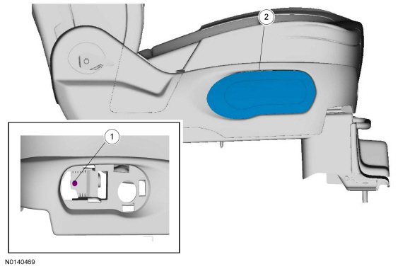
Dual Climate Controlled Seat Module (DCSM)
Special Tool(s)
Removal and Installation
NOTE: For component identification and locations, refer to Seat - Exploded View, Front in this section.
- When installing a new Dual Climate Controlled Seat Module (DCSM), carry out the appropriate steps in Programmable Module Installation (PMI). For additional information, refer to Section 418-01.
- WARNING:
Turn the ignition OFF and wait one minute to deplete the backup power
supply. Failure to follow this instruction may result in serious personal
injury or death in the event of an accidental deployment.
Turn the ignition OFF and wait at least one minute.
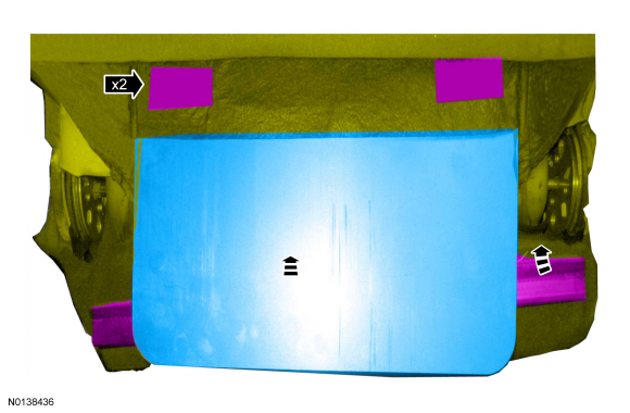
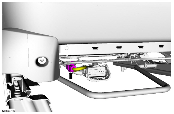
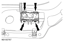
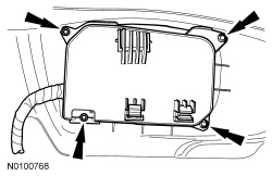
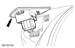
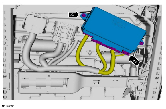
- From under the front passenger seat, remove the DCSM in the following
sequence.
- Remove the screws.
- Release the locking wedges on the 2 DCSM electrical connectors.
- Disconnect the electrical connectors.
- Remove the DCSM.
- To install, reverse the removal procedure.
- If a new DCSM has been installed, carry out the appropriate steps in Programmable Module Installation (PMI). For additional information, refer to Section 418-01.
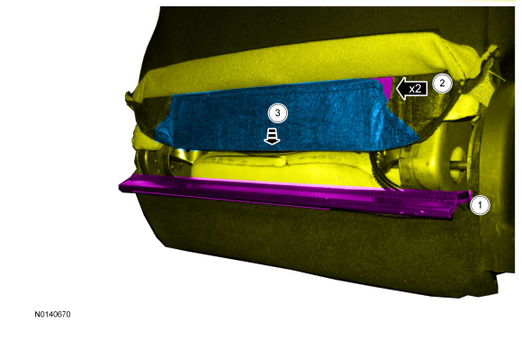
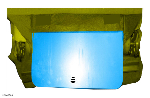
Seat Track - Front
Removal and Installation
NOTICE: If the passenger seat is equipped with an occupant classification sensor bladder system, to prevent system failure, it is necessary to carry out the occupant classification sensor system reset when a front passenger seat cushion is disassembled, a new cushion cover is installed or an OCS is installed. A scan tool is used to carry out the OCS system reset.
NOTE: For component identification and locations, refer to Seat - Exploded View, Front.
All seats
- Remove the seat backrest. Refer to Seat Backrest - Front.
- Detach the cushion cover retainers and remove the cushion cover and foam pad from the cushion frame.
Passenger seat without Active Motion massage adjuster
- If equipped with heated seats, disconnect the cushion heater mat electrical connector and separate the wire harness retainer from the front of the seat.
- Separate the OCSM.
- Bend the locking tab down using a screwdriver.
- Slide the OCSM off of the bracket.
- Disconnect the OCSM connector.
- Detach the OCS bladder pin-type retainers and access the underside.
- NOTICE: Failure to correctly route the OCS (id=245)Occupant
Classification System (OCS) components may cause component failure and
incorrect operation of the OCS (id=245)OCS.
Route the OCS bladder hoses through the seat cushion frame.
Seats with Active Motion massage adjuster
- Detach the Active Motion massage adjuster hose retainers.
- Detach the Active Motion massage adjuster pin-type retainers.
- Route the Active Motion massage adjuster hoses through the cushion support wires and remove the assembly.
All seats
- Remove the seat position sensor. Refer to Section 501-20B.
- Remove the safety belt buckle. Refer to Section 501-20A.
- If equipped, remove the Driver Seat Module (DSM). Refer to Driver Seat Module (DSM).
- If equipped, remove the Dual Climate Controlled Seat Module (DCSM). Refer to Dual Climate Controlled Seat Module (DCSM).
- For a passenger seat equipped with Active Motion massage adjuster, remove the OCSM. Refer to Section 501-20B.
- If equipped with climate controlled seats, remove the TED. Refer to Seat Cushion Thermo-Electric Device.
- To install, reverse the removal procedure.
Seat Track Motor - Front
General Equipment
- Drill(s)
Material
Removal
WARNING: Wear protective gloves when handling components or parts that have pointed or sharp edges. Failure to follow this instruction may result in serious personal injury.
NOTE: Typical driver seat shown, others similar.
- Remove the front seat. Refer to Seat - Front.
- If equipped.

- If equipped with Active Motion massage.

-
- -
- -
- -
- If equipped with Active Motion massage.
- NOTE: Connectors and location may vary due to vehicle configuration.
- If equipped.

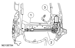
- NOTE: Seat cushion wire harness take-outs will vary with seat option content. Note the wire harness routing, attachment points and connections to the horizontal seat motor and bracket for installation.

Installation
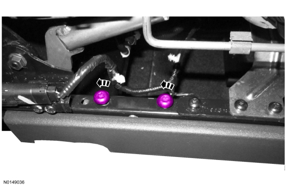
- NOTE: Applying pressure to the lower seat track rail forward or
backward can aid in bolt hole alignment.
On both sides.
- NOTICE: When using a drill to move the seat track, do not move
the seat track to its forward or rearward end of travel stops. Doing so can
result in damage to the seat track requiring its replacement.
NOTE: Be sure to drive the seat track evenly or the track will bind during movement.
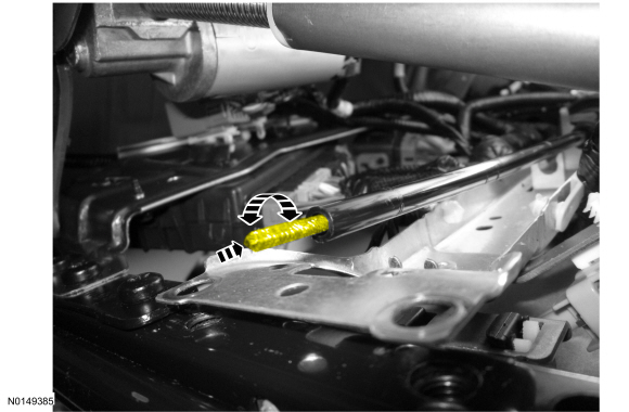
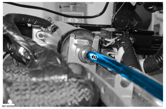
NOTE: Rotate the cables using 2 drills operating at similar speeds to most efficiently position the seat track.
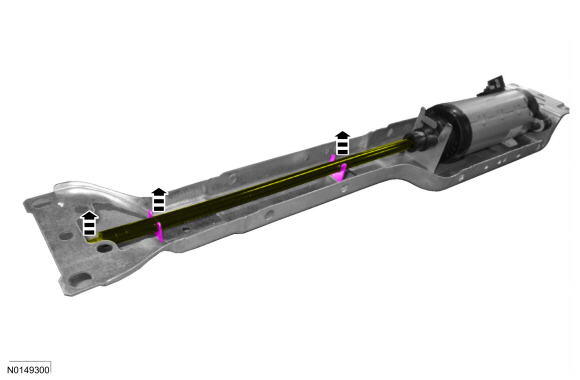
Align the seat track on both sides.
General Equipment: Drill(s).- Insert the original seat track motor cables into the inboard and outboard gearbox and seat track rails.
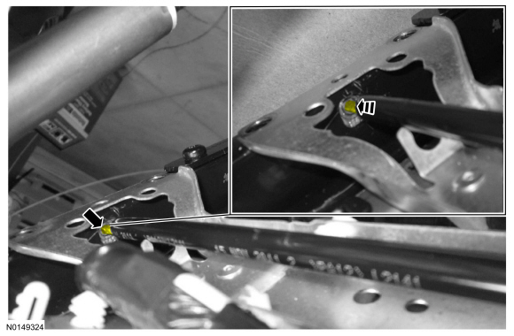
- Drive each gearbox and seat track uniformly until the rear edge of the upper and lower seat tracks are flush.
- The rear edges of the upper and lower seat track rails must align with each other on both sides.
- On both sides.
- NOTE: Applying pressure to either the upper or lower seat track
rail can aid in bolt hole alignment.
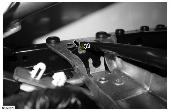
- Install the horizontal motor and bracket assembly onto the seat track making sure the bracket is positioned between the seat belt anchor bracket and the upper seat track rail.
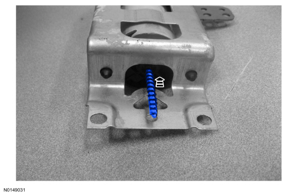
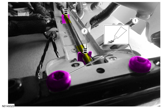
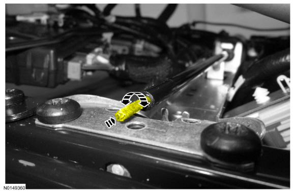
- Insert the small cable through the seat track rail and into the gearbox hole.
- Apply Threadlock and Sealer to the 2 bolts and tighten to 24 Nm (18 lb-ft).
- NOTE: The cable felt should not be visible when the cable is
correctly engaged to the horizontal motor square drive.
- Push the cable into the horizontal motor square drive twisting back and forth to engage the cable.
- NOTE: Applying pressure to either the upper or lower seat track
rail can aid in bolt hole alignment.
- Apply Threadlock and Sealer to the 2 bolts and tighten to 24 Nm (18 lb-ft).
- -
- From beneath the seat, route, attach and connect the seat cushion wire harness as noted during removal.
- If equipped.
- NOTE: Connectors and location may vary due to vehicle configuration.

-
- If equipped with Active Motion massage.
- -
- -
- -
- If equipped with Active Motion massage.

- If equipped.

- Install the front seat. Refer to Seat - Front.
- On vehicles with memory seat, operate the horizontal motor in both directions through the full range of travel to allow the DSM to correctly register stop positions and prevent premature stopping points after the repair is complete.
Front Seat Motor Cable
Removal
WARNING: Wear protective gloves when handling components or parts that have pointed or sharp edges. Failure to follow this instruction may result in serious personal injury.
- Remove the seat. Refer to Seat - Front.
- If equipped.
- If equipped with Active Motion massage.
-
- -
- -
- -
- If equipped with Active Motion massage.

- NOTE: Connectors and location may vary due to vehicle configuration.


Installation
NOTE: The front seat motor cable service part for the driver seat is different than the service part for passenger seat. Make sure to install the correct service part required for the seat.
- NOTE: The cable felt covering should not be visible when the
cable is correctly engaged to the horizontal motor square drive.
- Push the cable into the horizontal motor square drive twisting back and forth to engage the cable.
- NOTE: Connectors and location may vary due to vehicle configuration.
-
- If equipped with Active Motion massage.
- -
- -
- -

- If equipped with Active Motion massage.

- If equipped.

- Install the front seat. Refer to Seat - Front.
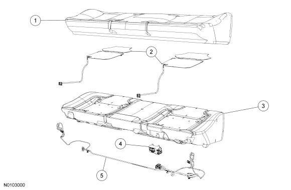
Seat Cushion - Rear
Removal and Installation
- From under the front of the cushion assembly, push the 2 cushion floor latch release levers toward the driver side, while lifting up to disengage the front of the cushion assembly.
- NOTE: RH electrical connectors on top, LH on bottom.
Remove the cushion assembly in the following sequence.
- Push the cushion back as far as possible.
- Lift up and pull forward at the rear outboard ends of the cushion, disengaging the wires from the retainer hooks.
- Disconnect the heated seat electrical connector(s) (if equipped).
- Remove the cushion.
- To install, reverse the removal procedure.
- Before installation, make sure the safety belts and buckles are accessible to the occupants.
Seat Backrest - Rear
40 Percent Backrest
60 Percent Backrest
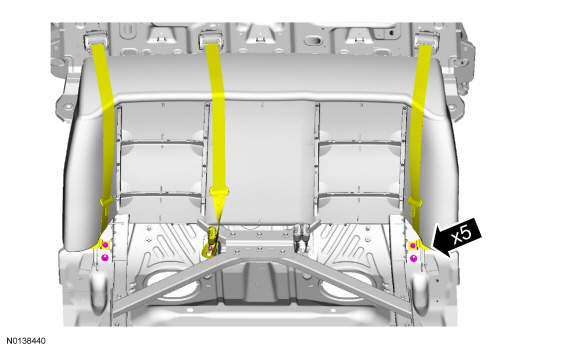
Removal and Installation
- Remove the rear seat cushion. For additional information, refer to Seat Cushion - Rear in this section.
- Remove the backrest-to-floor nut(s).
- For 60 percent seat, remove the 3 backrest-to-floor nuts.
- To install, tighten to 48 Nm (35 lb-ft).
- For 40 percent seat, remove the backrest-to-floor nut.
- To install, tighten to 48 Nm (35 lb-ft).
- For 60 percent seat, remove the 3 backrest-to-floor nuts.
- Remove the affected backrest in the following sequence.
- Pull the release strap at the upper outboard end of the affected backrest and fold the backrest forward.
- Lift the backrest bracket(s) off the floor stud(s).
- Slide the pivot out of the seat and remove the backrest.
- To install, reverse the removal procedure.
- Before installation, make sure the safety belts are accessible to the occupants.
Seat Backrest - Rear, Police Package
Removal and Installation
NOTE: Removal steps in this procedure may contain installation details.
- Remove the rear seat cushion. Refer to Seat Cushion - Rear.
-
- To install, tighten to 48 Nm (35 lb-ft).
- NOTE: Make sure the rear seat back has been released from the latches on both sides of the seat back.
- NOTE: Move safety belts aside to ease the removal of the rear seat back.
- To install, reverse the removal procedure.
- After installation, make sure the safety belts are accessible.
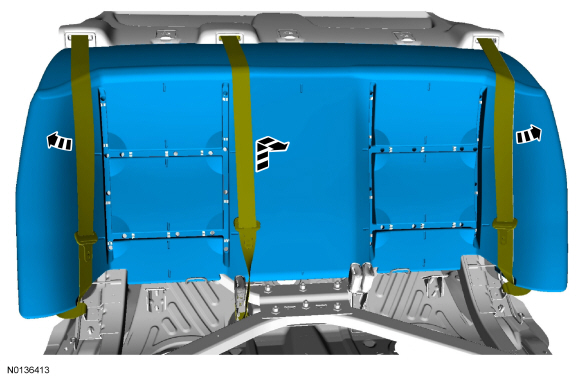
Seat Bolster - Rear
Removal and Installation
NOTE: LH shown, RH similar.
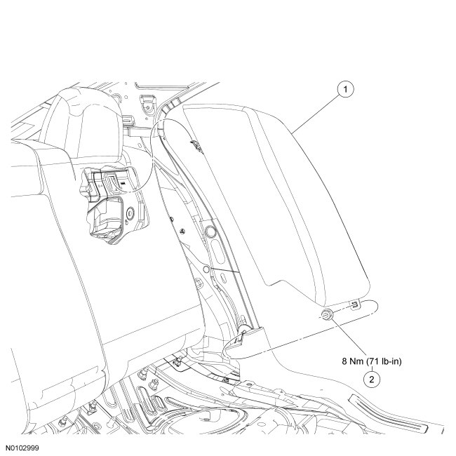
Bolsters having been previously removed
- Remove the nut from the lower retainer stud.
- To install, tighten to 8 Nm (71 lb-in).
All bolsters
- Pull the rear door scuff plate up at the front and separate from the B-pillar trim panel.
- At the same time, separate the seat bolster at the bottom and rear door scuff plate at the rear from the stud. Remove the scuff plate.
- Slide the seat bolster down and remove.
- To install, reverse the removal procedure.
- When installing the seat bolster, install a M6 x 1.0 nut on the
lower retainer stud.
- To install, tighten to 8 Nm (71 lb-in).
- When installing the seat bolster, install a M6 x 1.0 nut on the
lower retainer stud.
Seat - Exploded View, Second Row
40 Percent Backrest
60 Percent Backrest
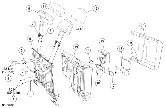
- For additional information, refer to the procedures in this section.
Seat Backrest Cover - Rear, 40 Percent
Removal
NOTE: For parts identification and location, refer to Seat - Exploded View, Second Row in this section.
- Remove the rear seat backrest. For additional information, refer to Seat Backrest - Rear in this section.
- Remove the 2 head restraint guide sleeves. For additional information, refer to Head Restraint Guide Sleeve - Front in this section.
- Release the tabs and remove the pivot grommet.
- If equipped, separate the heater mat electrical connector.
- Disengage the backrest cover J-clip at the bottom, separate the hook-and-loop strips and disengage the retainers on each side.
- NOTICE: Use care when separating the backrest cover wires from
the backrest foam pad clips, or the clips can be torn from the backrest foam
pad.
NOTICE: Use care when separating the backrest cover from the hook-and-loop strip, or the hook-and-loop strip may be torn from the backrest foam pad.
Release the hook-and-loop strips, disengage the wires from the clips and remove the backrest cover.- Route the heated seat mat pigtail and connector out of the backrest cover (if equipped).
Installation
- Position the backrest cover to the backrest foam pad. Attach the wires
to the clips and the hook-and-loop strips.
- Route the heated seat mat wire harness and connector through the backrest cover (if equipped).

- Route the latch release strap through the backrest cover.

- Attach the backrest cover hook-and-loop strips and engage the retainers on each side.
- Engage the backrest cover J-clips and hook-and-loop strips at the
bottom.
- Attach the heater mat electrical connector (if equipped).
- Install the pivot grommet.
- Install the 2 head restraint guide sleeves. For additional information, refer to Head Restraint Guide Sleeve - Front in this section.
- Install the rear seat backrest. For additional information, refer to Seat Backrest - Rear in this section.
Seat Backrest Cover - Rear, 60 Percent
Removal and Installation
NOTE: For parts identification and location, refer to Seat - Exploded View, Second Row in this section.
- Remove the rear seat backrest. For additional information, refer to Seat Backrest - Rear in this section.
- Remove the 4 head restraint guide sleeves. For additional information, refer to Head Restraint Guide Sleeve - Front in this section.
- If equipped, separate the heater mat electrical connector.
- Disengage the backrest cover J-clip at the bottom, separate the hook-and-loop strips and disengage the retainers on each side.
- Remove 2 bolts and armrest with bracket.
- Remove the 2 pin-type retainers at the armrest pocket.
- NOTICE: Use care when separating the backrest cover wires from
the backrest foam pad clips, or the clips can be torn from the backrest foam
pad.
NOTICE: Use care when separating the backrest cover from the hook-and-loop strip, or the hook-and-loop strip may be torn from the backrest foam pad.
Release the hook-and-loop strips, disengage the wires from the clips and remove the backrest cover.- Route the heated seat mat wire harness and connector out of the backrest cover (if equipped).
Installation
- Position the backrest cover to the backrest foam pad. Attach the wires
to the clips and the hook-and-loop strips.
- Route the heated seat mat wire harness and connector through the backrest cover (if equipped).
- Route the latch release strap through the backrest cover.
- Install the 2 pin-type retainers at the armrest pocket.
- Position the armrest with bracket and install the 2 bolts.
- Tighten to 10 Nm (89 lb-in).
- Attach the backrest cover hook-and-loop strips and engage the retainers on each side.
- Engage the backrest cover J-clips and hook-and-loop strips at the
bottom.
- Attach the heater mat electrical connector (if equipped).
- Install the 4 head restraint guide sleeves. For additional information, refer to Head Restraint Guide Sleeve - Front in this section.
- Install the rear seat backrest. For additional information, refer to Seat Backrest - Rear in this section.
Seat Backrest Cover - Rear, Police Package
Removal and Installation
- Remove the rear seat backrest. Refer to Seat Backrest - Rear, Police Package.
- On both sides.
- NOTICE: Use care when separating the backrest cover clips from the backrest foam pad slots, or the slots can be torn from the backrest foam pad.
- To install, reverse the removal procedures.
Seat Cushion Cover - Rear
Removal and Installation
NOTE: For parts identification and location, refer to Seat - Exploded View, Second Row in this section.
- Remove the rear seat cushion. For additional information, refer to Seat Cushion - Rear in this section.
- If equipped, route the heated seat jumper harness out of the cushion cover retainers on each side.
- From underneath the cushion assembly, remove the hog rings retaining the
cushion trim cover wires and draw strings to the cushion foam pad wires.
- At installation, route the heated seat mat wire harness under the draw string.
- NOTICE: Use care when separating the cushion cover wires from
the cushion foam pad clips, or the clips can be torn from the cushion foam
pad.
Separate the cushion cover wires from the foam pad clips and remove the cover.
- To install, reverse the removal procedure.
Seat Backrest Heater Mat - Rear
Removal
NOTICE: The heater mat is not designed to be separated from the foam pad. Doing so will damage the foam pad. Install a new foam pad and heater mat. Failure to follow this instruction can result in seat component damage and system failure.
NOTE: For parts identification and location, refer to Seat - Exploded View, Second Row in this section.
- Remove the backrest cover. For additional information, refer to Seat Backrest Cover - Rear, 40 Percent or Seat Backrest Cover - Rear, 60 Percent in this section.
- Remove the backrest foam pad from the frame. Discard the foam pad with heater mat.
Installation
- NOTE: 40 percent shown, 60 percent similar.
Install a new backrest heater mat onto the new backrest foam pad.
- Route the backrest heater mat pigtail and electrical connector through the backrest foam pad to the other side.
- Position the backrest heater mat onto the backrest foam pad so the
opening aligns to the clips in the backrest foam pad.
- Tuck the backrest heater mat into the backrest foam pad trench.
- Make sure the backrest heater mat stays in place, remove the paper strips from under the backrest heater mat and adhere to the backrest foam pad, laying it flat with no wrinkles.
- Route the heater mat wire harness in the foam pad trench.
- Install the backrest cover. For additional information, refer to Seat Backrest Cover - Rear, 40 Percent or Seat Backrest Cover - Rear, 60 Percent in this section.
Seat Armrest - Rear
Removal and Installation
NOTE: For parts identification and location, refer to Seat - Exploded View, Second Row in this section.
- Using the latch release strap at the upper outboard side of the 60 percent backrest, lower the backrest.
- Disengage the backrest cover retainer at the bottom, separate the hook and loop strips and disengage the retainer on the side.
- Remove 2 bolts and armrest with bracket.
- To install, tighten to 10 Nm (89 lb-in).
- Remove the screw at each armrest side cover, slide up and remove.
- To install, reverse the removal procedure.
Seat Cushion Heater Mat - Rear
Removal
NOTICE: The heater mat is not designed to be separated from the foam pad. Doing so will damage the foam pad. Install a new foam pad and heater mat. Failure to follow this instruction can result in seat component damage and system failure.
NOTE: For parts identification and location, refer to Seat - Exploded View, Second Row in this section.
- Remove the rear seat cushion cover. For additional information, refer to Seat Cushion Cover - Rear in this section.
- Disconnect and remove the heated seat module and cushion wire harness.
- Remove the cushion foam pad from the frame. Discard the cushion foam pad with heater mat.
Installation
- Install new cushion heater mats onto a new cushion foam pad.
- Position a cushion heater mat onto the cushion foam pad so the opening aligns to the clips in the cushion foam pad.
- Tuck the cushion heater mat into the cushion foam pad trenches.
- Make sure the cushion heater mat stays in place, remove the paper strips from under the cushion heater mat and adhere to the cushion foam pad, laying it flat with no wrinkles.
- Route the cushion heater mat wire harness and electrical connector through the cushion foam pad to the other side.
- Install and connect the cushion wire harness and heated seat module.
- Install the rear seat cushion cover. For additional information, refer to Seat Cushion Cover - Rear in this section.
Heated Seat Module - Rear
Removal and Installation
NOTE: For parts identification and location, refer to Seat - Exploded View, Second Row in this section.
- Remove the rear seat cushion. For additional information, refer to Seat Cushion - Rear in this section.
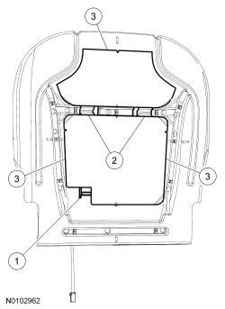
- At the right rear of the seat cushion, remove the hog rings necessary to access the heated seat module.
- Remove the tie strap, disconnect the 2 electrical connectors and remove the heated seat module.
- To install, reverse the removal procedure.
- Carry out module auto-configuration:
- Start the vehicle and push the low button on either heated seat switch.
- Operate the heated seats, monitor the indicators and verify the system is operating correctly in high and low.
Heated Seat Switch - Rear
Removal and Installation
- Remove the rear panel from the floor console in the following sequence.
- Pull to disengage the retainers and separate the rear panel.
- Disconnect the LH and RH heated seat switch electrical connectors.
- Disconnect the power point electrical connector (if equipped).
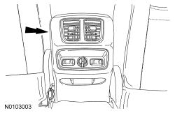
- Release the clips and remove the heated seat switch(es).
- To install, reverse the removal procedure.
 General Procedures
Accessing Mounting Bolts On an Inoperative Power Seat
General Equipment
Drill(s)
WARNING: Wear protective gloves when handling components or parts that
have pointed or sharp edges. Failure to foll ...
 Disassembly and Assembly
Seat Backrest - Front
Disassembly
Seat Backrest - Trim Parts
Seat Backrest - Frame Parts With Manual Lumbar and Static Lumbar
Seat Backrest - Frame Parts With Power Lumbar
Seat Cushion - With Ac ...
Other materials:
Installation
Engine
Special Tool(s)
Material
Lubricate the torque converter pilot hub with Multi-Purpose Grease.
Remove the Torque Converter Retainer and bolt.
NOTE: Align the torque converter stud marked during removal with
the flexplate.Using the Floor Crane and Spreader Bar, assemble t ...
Remote control
Integrated Keyhead Transmitters (IKTs) (If Equipped)
Use the key blade to start your
vehicle and unlock or lock the
driver door from outside your
vehicle. The transmitter portion
functions as the remote control.
Note: Your vehicle’s keys came
with a security label that provides
importa ...
Diagnosis and Testing
Handles, Locks, Latches and Entry Systems
Special Tool(s)
Material
DTC Charts
Diagnostics in this manual assume a certain skill level and knowledge of
Ford-specific diagnostic practices. Refer to Diagnostic Methods in Section
100-00 for information about these practices.
DDM DTC C ...
