Valve Clearance Check
- Remove the RH fender splash shield. For additional information, refer to Section 501-02.
- Remove the valve cover. For additional information, refer to Valve Cover in this section.
- NOTE: Turn the engine clockwise only, and only use the crankshaft
bolt.
NOTE: Before removing the camshafts, measure the clearance of each valve at base circle, with the lobe pointed away from the tappet. Failure to measure all clearances prior to removing the camshafts will necessitate repeated removal and installation and wasted labor time.
Use a feeler gauge to measure the clearance of each valve and record its location.
- NOTE: The number on the valve tappet only reflects the digits
that follow the decimal. For example, a tappet with the number 0.650 has the
thickness of 3.650 mm.
NOTE: The nominal clearance is:
- intake: 0.25 mm (0.0095 in).
- exhaust: 0.36 mm (0.0142 in).
NOTE: The acceptable clearances after being fully installed are:
- intake: 0.19-0.31 mm (0.007-0.012 in).
- exhaust: 0.30-0.42 mm (0.012-0.017 in).
Select the closest tappet size to the ideal tappet thickness available and mark the installation location.
- If any tappets do not measure within specifications, install new tappets in these locations. For additional information, refer to Valve Tappets in this section.
Balance Shaft Backlash
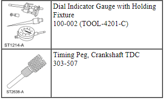
Special Tool(s)
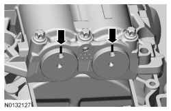
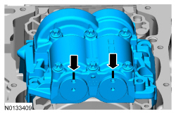
- Install the Crankshaft TDC Timing Peg and rotate the crankshaft slowly clockwise until the crankshaft balance weight is up against the Crankshaft TDC Timing Peg. The engine is now at TDC.

- Mark the balancer unit and shafts on the top for reference that the balancer unit is at TDC.
- NOTE: Due to the precision interior construction of the balancer
unit, it should not be disassembled.
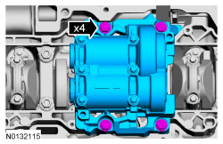
Remove the 4 bolts and the balancer unit.
- Remove the adjustment shims from the seat faces of the balancer unit.
- NOTICE: Visually inspect the balancer unit gear for damage and
verify that the shaft turns smoothly. If there is any damage or malfunction,
replace the balancer unit.
Install the master adjustment shims (No. 50) on the seat faces of the balancer unit.
- With the balancer unit shaft marks at the TDC position, slowly install the balancer unit to the cylinder block to avoid interference between the crankshaft drive gear and the balancer unit driven gear.

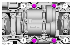
- Install the balancer unit bolts.
- Tighten in the sequence shown in 2 stages.
- Stage 1: Tighten to 25 Nm (18 lb-ft).
- Stage 2: Tighten to 42 Nm (31 lb-ft).
- Tighten in the sequence shown in 2 stages.
- Remove the Crankshaft TDC Timing Peg.
- Rotate the crankshaft to confirm that there are no meshing problems between the balancer unit gear and the crankshaft gear.
- Install the Crankshaft TDC Timing Peg and rotate the crankshaft slowly
clockwise until the crankshaft balance weight is up against the
Crankshaft TDC Timing Peg.
- Remove the Crankshaft TDC Timing Peg.
- NOTE: Measure the backlash and verify that it is within specified
range at all of the following 6 positions: 10 degrees, 30 degrees, 100
degrees, 190 degrees, 210 degrees and 280 degrees. It will be necessary to
reset the measuring equipment between measurements.
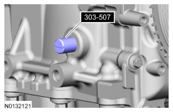
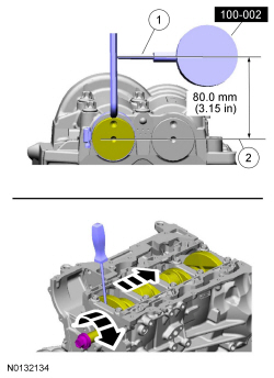
NOTE: The measurement must be taken with the Dial Indicator Gauge with Holding Fixture, a 5-mm Allen wrench and worm clamp set up as shown. Mark the Allen wrench with a file 80 mm (3.149 in) above the driven gear shaft center. Make sure the worm clamp and Allen wrench are not touching the balance shaft housing.
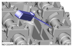
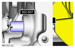
NOTE: For an accurate measurement while measuring the gear backlash, insert a screwdriver as shown into the crankshaft No. 1 crankweight area and set both the rotation and the thrust direction with the screwdriver, using a prying action as shown.
Position the Dial Indicator Gauge with Holding Fixture as shown. Measure the gear backlash.- Position the Dial Indicator Gauge with Holding Fixture (1) on the Allen wrench 80 mm (3.149 in) above the driven gear shaft center (2) on the balancer unit.
- Rotate the crankshaft clockwise and measure the backlash at all of the following 6 positions: 10 degrees, 30 degrees, 100 degrees, 190 degrees, 210 degrees and 280 degrees.

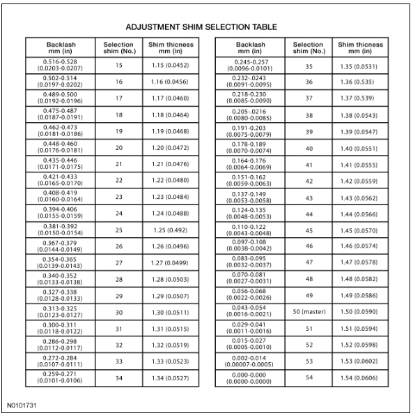
- NOTE: If maximum backlash exceeds 0.120 mm (0.0047 in), install a
new balancer unit.
Using the backlash measurement, select the proper shims from the Adjustment Shim Selection Table.
- Remove the balancer unit from the cylinder block.
- Install the selected adjustment shims on the seat faces of the balancer unit.
- Install the Crankshaft TDC Timing Peg and rotate the crankshaft slowly clockwise until the crankshaft balance weight is up against the Crankshaft TDC Timing Peg. The engine is now at TDC.

- With the balancer unit shaft marks in the TDC position, slowly install the balancer unit to the cylinder block to avoid interference between the crankshaft drive gear and the balancer unit driven gear.
- Install the balancer unit bolts.
- Tighten in the sequence shown in 2 stages.
- Stage 1: Tighten to 25 Nm (18 lb-ft).
- Stage 2: Tighten to 42 Nm (31 lb-ft).
- Tighten in the sequence shown in 2 stages.

- Remove the Crankshaft TDC Timing Peg.

- NOTE: Remeasure the backlash and verify that it is within
specified range at all of the following 6 positions: 10 degrees, 30 degrees,
100 degrees, 190 degrees, 210 degrees and 280 degrees. It will be necessary
to reset the measuring equipment between measurements.
NOTE: The measurement must be taken with the Dial Indicator Gauge with Holding Fixture, a 5-mm Allen wrench and worm clamp set up as shown. Mark the Allen wrench with a file 80 mm (3.149 in) above the driven gear shaft center. Make sure the worm clamp and Allen wrench are not touching the balance shaft housing.
NOTE: For an accurate measurement while measuring the gear backlash, insert a screwdriver as shown into the crankshaft No. 1 crankweight area and set both the rotation and the thrust direction with the screwdriver, using a prying action as shown.
Position the Dial Indicator Gauge with Holding Fixture as shown. Measure the gear backlash.- Position the Dial Indicator Gauge with Holding Fixture (1) on the Allen wrench 80 mm (3.149 in) above the driven gear shaft center (2) on the balancer unit.
- Rotate the crankshaft clockwise and measure the backlash at all of the following 6 positions: 10 degrees, 30 degrees, 100 degrees, 190 degrees, 210 degrees and 280 degrees.
- If the backlash exceeds the specified range of 0.020 to 0.120 mm (0.0008 to 0.0047 in), install a new balancer unit and repeat the procedure.
 Specifications, Description and Operation, Diagnosis and Testing
SPECIFICATIONS
Material
General Specifications
Torque Specifications
a Refer to the procedure in this section.
b 15 Nm plus an additional 60 degrees
c 8 Nm plus an additional ...
 In-Vehicle Repair
Intake Manifold
Removal
With vehicle in NEUTRAL, position it on a hoist. For additional
information, refer to Section 100-02.
Loosen the 4 retainers and remove the underbody shield.
...
Other materials:
Changing a fuse
Fuses
WARNING: Always replace a fuse with one that has the
specified amperage rating. Using a fuse with a higher amperage
rating can cause severe wire damage and could start a fire.
If electrical components in your
vehicle are not working, a fuse may
have blown. Blown fuses are
identified b ...
Audible warnings and indicators
Key In Ignition Warning Chime
Sounds when the key is left in the ignition in the off or accessory
position and the driver’s door is opened.
Keyless Warning Alert (If Equipped)
Sounds the horn twice when you exit your vehicle with the intelligent
access key, after the last door is closed and y ...
In-Vehicle Repair
Intake Manifold
Removal
NOTICE: During engine repair procedures, cleanliness is extremely
important. Any foreign material, including any material created while cleaning
gasket surfaces that enters the oil passages, coolant passages or the oil pan,
may cause engine failure.
NOTICE: Whene ...
