Intake Manifold
Removal
- With vehicle in NEUTRAL, position it on a hoist. For additional information, refer to Section 100-02.
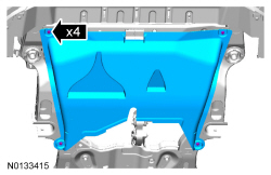
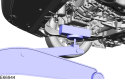
- Loosen the 4 retainers and remove the underbody shield.

- Disconnect the battery ground cable. For additional information, refer to Section 414-01.
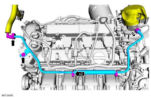
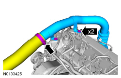
- Disconnect the EVAP tube from the CAC outlet tube. For additional
information, refer to the quick connect coupling procedure in Section
310-00.
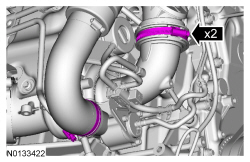
- Loosen the clamp and disconnect the CAC outlet tube from the TB.

- Disconnect the FRP sensor and MAP sensor electrical connectors.
- Detach the 2 EVAP tube retainers from the intake manifold.
- Detach the heater hose retaining clip.
- Disconnect the EVAP tube from the intake manifold. For additional information, refer to the quick connect coupling procedure in Section 310-00.
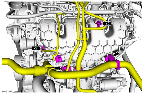
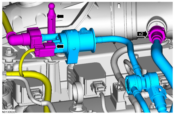
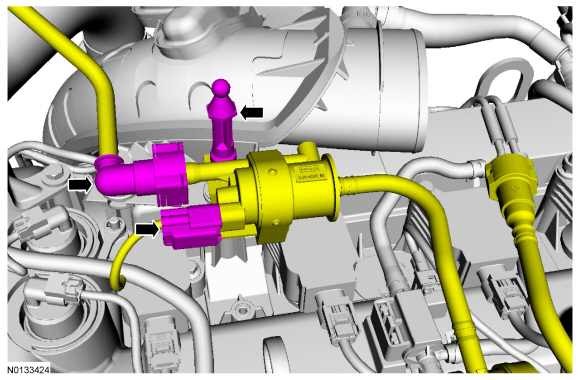
- Disconnect the EVAP tube from the EVAP canister purge valve and
the ACL outlet pipe. For additional information, refer to the quick connect
coupling procedure in Section 310-00.
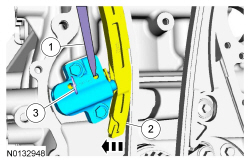
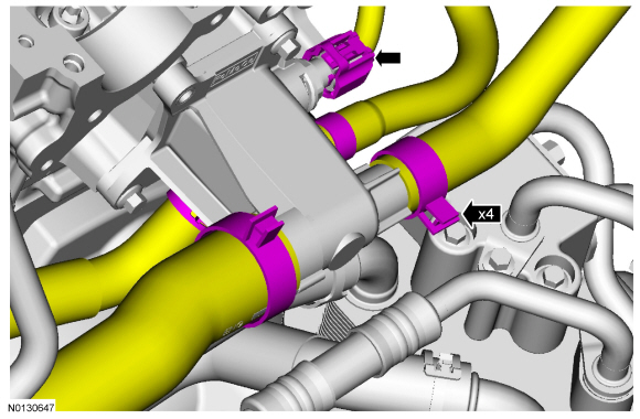
- Disconnect the EVAP canister purge valve electrical connector.
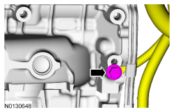
- Remove the engine cover mounting pin.
- Remove the EVAP canister purge valve and EVAP tube assembly.

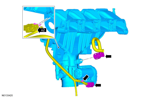
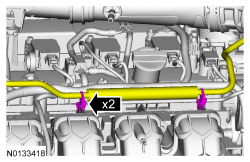
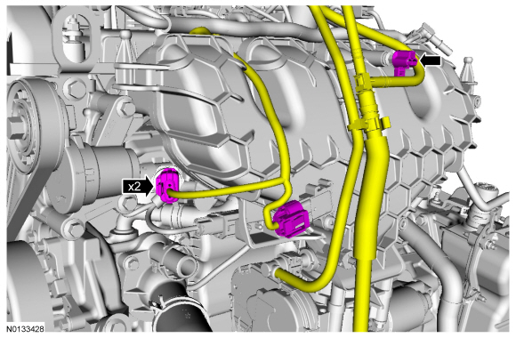
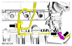
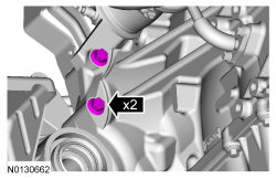
- Detach the 2 fuel tube retainers from the intake manifold.

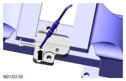
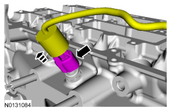
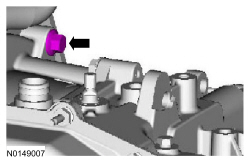
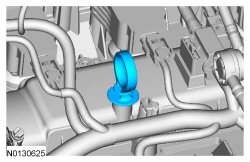
- Depress the red quick connect locking ring and pull the vacuum tube out
of the quick connect fitting.
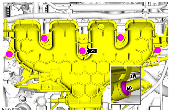
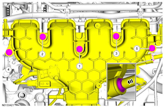
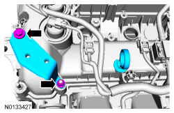
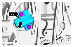
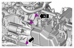
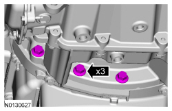
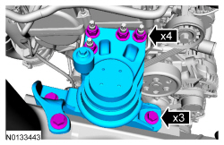
- Remove the 5 intake manifold bolts and position the intake manifold forward.
- Disconnect the TB electrical connector and detach the wiring harness
retainer from the TB.
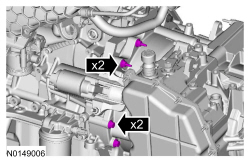
- Detach the 2 KS wiring harness retainers from the intake manifold.
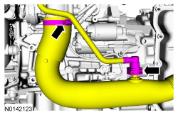
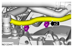
- Disconnect the crankcase ventilation oil separator tube and remove the intake manifold.

Installation
NOTICE: If the engine is repaired or replaced because of upper engine failure, typically including valve or piston damage, check the intake manifold for metal debris. If metal debris is found, install a new intake manifold. Failure to follow these instructions can result in engine damage.
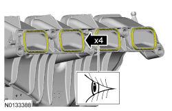
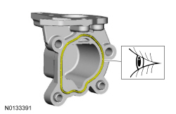
- Visually inspect the intake manifold gaskets for nicks, cuts and abrasions. If these conditions are not present, the gaskets may be re-used.
- Position the intake manifold and connect the crankcase ventilation oil
separator tube.
- Attach the 2 KS wiring harness retainers to the intake manifold.
- Connect the TB electrical connector and attach the wiring harness retainer to the TB.
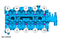
- Install the intake manifold and the 5 bolts.
- Tighten in the sequence shown to 20 Nm (177 lb-in).
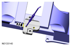
- Install the vacuum tube into the quick connect coupling.
- Attach the 2 fuel tube retainers to the intake manifold.
- Install the EVAP canister purge valve and EVAP tube assembly.
- Install the engine cover mounting pin.
- Tighten to 5 Nm (44 lb-in).
- Connect the EVAP canister purge valve electrical connector.
- Connect the EVAP tube to the EVAP canister purge valve and the ACL outlet pipe. For additional information, refer to the quick connect coupling procedure in Section 310-00.
- Install the engine cover mounting pin.
- Connect the FRP sensor and MAP sensor electrical connectors.
- Connect the EVAP tube to the intake manifold. For additional information, refer to the quick connect coupling procedure in Section 310-00.
- Attach the 2 EVAP tube retainers to the intake manifold.
- Attach the heater hose retaining clip.

- Connect the CAC outlet tube to the TB.
- Tighten the clamp to 5 Nm (44 lb-in).
- Connect the EVAP tube to the CAC outlet tube. For additional information, refer to the quick connect coupling procedure in Section 310-00.
- Install the underbody shield and the 4 retainers.

- Connect the battery ground cable. For additional information, refer to Section 414-01.
Valve Cover
Material
Removal
NOTICE: During engine repair procedures, cleanliness is extremely important. Any foreign material, including any material created while cleaning gasket surfaces, that enters the oil passages, coolant passages or the oil pan can cause engine failure.
- With the vehicle in NEUTRAL, position it on a hoist. For additional information, refer to Section 100-02.
- Release the fuel system pressure. For additional information, refer to Section 310-00.
- Disconnect the battery ground cable. For additional information, refer to Section 414-01.
- Loosen the 4 retainers and remove the underbody shield.

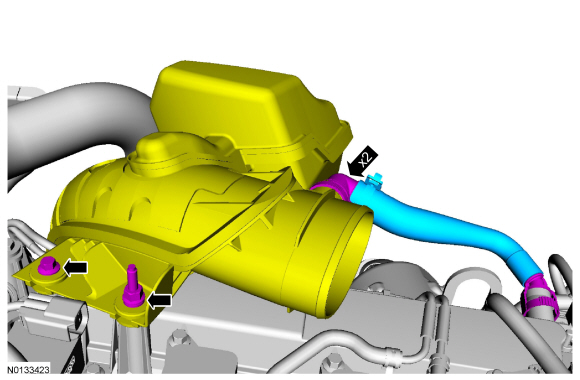
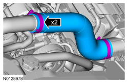
- Loosen the turbocharger inlet and outlet pipe clamps.
- Remove the ACL outlet pipe. For additional information, refer to Section 303-12.
- Remove the engine appearance cover mounting stud.
- Disconnect the EVAP canister purge valve electrical connector and vapor tube. For additional information, refer to the quick connect coupling procedure in Section 310-00.
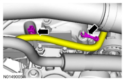
- Disconnect the 2 quick connect couplings and remove the crankcase
ventilation hose. For additional information, refer to the quick connect
coupling procedure in Section 310-00.
- Remove the bolt, the stud bolt and position the turbocharger inlet pipe aside.

- Loosen the CAC inlet tube clamp.
- Remove the 2 bolts and the CAC inlet/intermediate inlet tube assembly.

- Disconnect the fuel supply tube from the fuel jumper tube and the fuel
jumper tube from the fuel injection pump. For additional information, refer
to the quick connect coupling procedure in Section 310-00.
- Detach the 2 fuel tube retainers from the intake manifold.
- Remove the bolt and the fuel jumper tube.

- Remove the coil-on-plug assemblies. For additional information, refer to Section 303-07C.
- Remove the nut, the bolt and the CAC intermediate tube mounting bracket.
- Remove the oil level indicator.

- Disconnect the FRP sensor and the MAP sensor electrical connectors.
- Detach the EVAP tube retainer from the intake manifold.
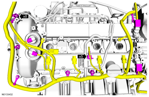
- Disconnect the 5 engine wiring harness electrical connectors.
- Detach the 8 wiring harness retainers.

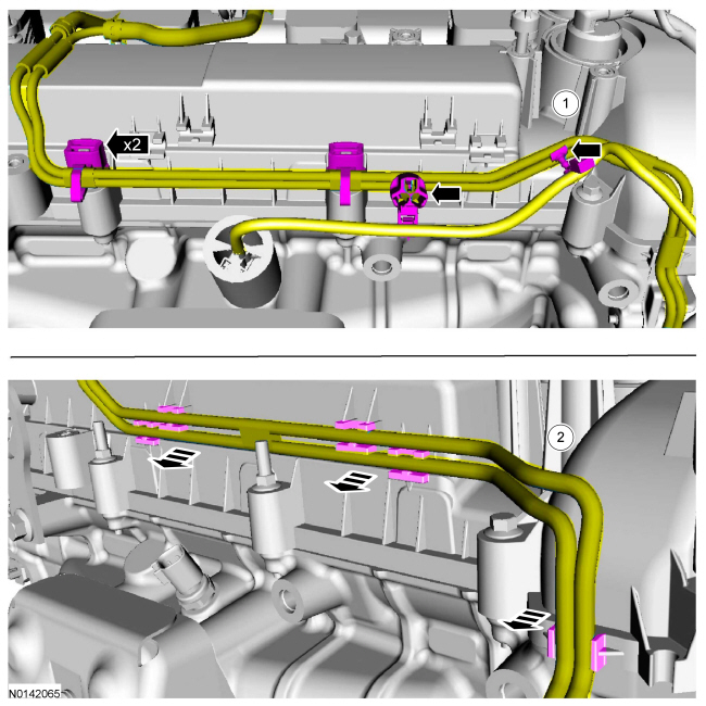
- Disconnect the brake booster vacuum tube and the turbocharger control
vacuum tube quick connect couplings. For additional information, refer to
the quick connect coupling procedure in Section 310-00.
- Detach the vacuum tube from the valve cover retaining tab.
- If equipped, disconnect the wiring harness retainers. Detach the vacuum
tubes from the valve cover and position the tubes aside.
- Early build vehicles equipped with metal vacuum tubes.
- Late build vehicles equipped with nylon vacuum tubes.
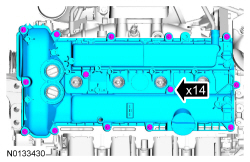
- Loosen the 14 valve cover retainers and remove the valve cover.
- Discard the valve cover gasket.
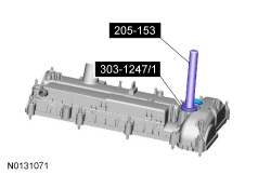
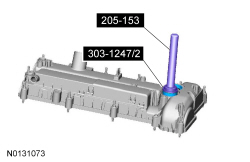
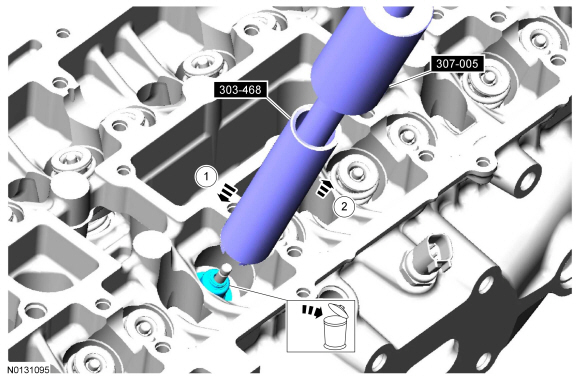
- NOTE: The VCT solenoid seals should only be replaced if they are
damaged.
Remove any damaged VCT solenoid seals using the VCT Spark Plug Tube Seal Remover and Handle.
Installation
- NOTICE: Do not use metal scrapers, wire brushes, power
abrasive discs or other abrasive means to clean the sealing surfaces. These
tools cause scratches and gouges which make leak paths.
Clean and inspect the sealing surfaces.
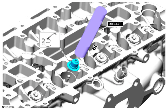
- NOTE: Installation of new seals is only required if damaged seals
were removed during disassembly of the engine.
Using the VCT Spark Plug Tube Seal Installer and Handle, install new VCT solenoid seals.
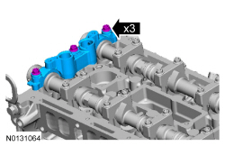
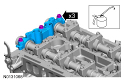
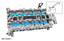
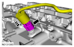
- Apply a 5.5 mm (0.216 in) drop of silicone gasket and sealant to the 6 locations shown.
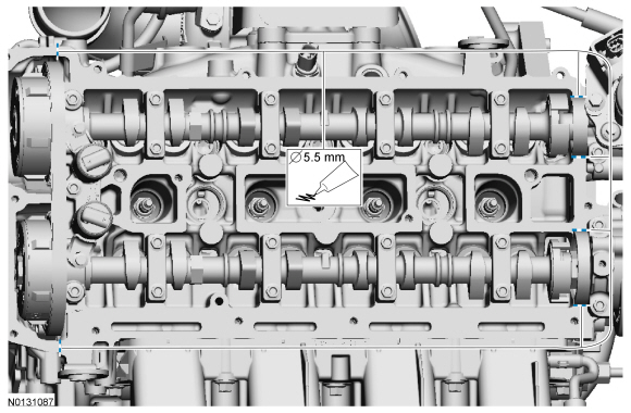
- NOTE: The valve cover must be secured within 10 minutes of
silicone gasket application. If the valve cover is not secured within 10
minutes, the sealant must be removed and the sealing area cleaned with metal
surface prep.
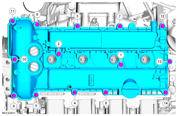
Using a new gasket install the valve cover.
- Tighten in the sequence shown to 10 Nm (89 lb-in).
- Attach the vacuum tubes to the valve cover. If equipped, connect the
wiring harness retainers.
- Early build vehicles equipped with metal vacuum tubes.
- Late build vehicles equipped with nylon vacuum tubes.

- Connect the brake booster vacuum tube and the turbocharger control
vacuum tube quick connect couplings. For additional information, refer to
the quick connect coupling procedure in Section 310-00.
- Attach the vacuum tube to the valve cover retaining tab.

- Connect the 5 engine wiring harness electrical connectors.
- Attach the 8 wiring harness retainers.
- Connect the FRP sensor and the MAP sensor electrical connectors.
- Attach the EVAP tube retainer to the intake manifold.

- Install the CAC intermediate tube mounting bracket, the nut and the
bolt.
- Tighten to 6 Nm (53 lb-in).
- Install the oil level indicator.
- Install the coil-on-plug assemblies. For additional information, refer to Section 303-07C.
- Install the fuel jumper tube and the bolt.
- Tighten to 8 Nm (71 lb-in).
- Connect the fuel supply tube to the fuel jumper tube and the fuel jumper tube to the fuel injection pump. For additional information, refer to the quick connect coupling procedure in Section 310-00.
- Attach the 2 fuel tube retainers to the intake manifold.
- Install the CAC inlet/intermediate inlet tube assembly and the 2 bolts.
- Tighten the bolts to 6 Nm (53 lb-in).
- Tighten the CAC inlet tube clamp to 8 Nm (71 lb-in).
- Position the turbocharger inlet pipe and install the bolt and stud bolt.
- Tighten to 5 Nm (44 lb-in).
- Position the crankcase ventilation hose and connect the 2 quick connect couplings. For additional information, refer to the quick connect coupling procedure in Section 310-00.
- Connect the EVAP canister purge valve electrical connector and vapor
tube. For additional information, refer to the quick connect coupling
procedure in Section 310-00.
- Install the engine appearance cover mounting stud.
- Tighten to 5 Nm (44 lb-in).
- Install the engine appearance cover mounting stud.

- Install the ACL outlet pipe. For additional information, refer to Section 303-12.
- Tighten the turbocharger inlet and outlet pipe clamps.
- Tighten to 5 Nm (44 lb-in).

- Install the underbody shield and the 4 retainers.
- Connect the battery ground cable. For additional information, refer to Section 414-01.
Crankshaft Pulley
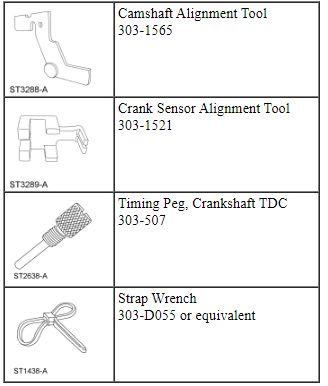
Special Tool(s)
Material
Removal
NOTICE: Do not loosen or remove the crankshaft pulley bolt without first installing the special tools as instructed in this procedure. The crankshaft pulley and the crankshaft timing sprocket are not keyed to the crankshaft. The crankshaft, the crankshaft sprocket and the pulley are fitted together by friction, using diamond washers between the flange faces on each part. For that reason, the crankshaft sprocket is also unfastened if the pulley bolt is loosened. Before any repair requiring loosening or removal of the crankshaft pulley bolt, the crankshaft and camshafts must be locked in place by the special service tools, otherwise severe engine damage can occur.
NOTICE: During engine repair procedures, cleanliness is extremely important. Any foreign material, including any material created while cleaning gasket surfaces, that enters the oil passages, coolant passages or the oil pan can cause engine failure.
- Release the fuel system pressure. For additional information, refer to Section 310-00.
- Remove the RH fender splash shield. For additional information, refer to Section 501-02.
- Loosen the 4 retainers and remove the underbody shield.

- Remove the accessory drive belt. For additional information, refer to Section 303-05.
- Remove the brake vacuum pump. For additional information, refer to Section 206-07.
- Remove the valve cover. For additional information, refer to Valve Cover in this section.
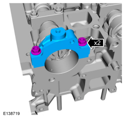
- Remove the 2 bolts and the rear intake camshaft cap.

- Using a wrench on the flats of the intake camshaft to prevent cam rotation, remove the brake vacuum pump adapter.

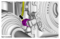
- Disconnect the CKP sensor electrical connector.
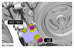
- Remove the 2 bolts and the CKP sensor.
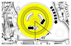
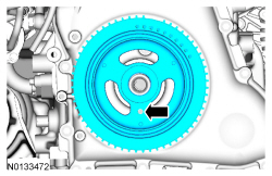
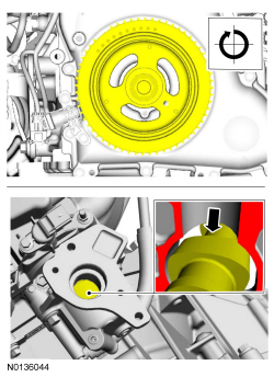
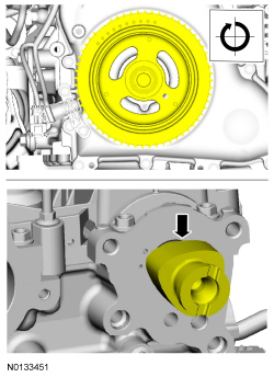
- Turn the crankshaft clockwise until the No.1 piston is 45 degrees BTDC using the guide holes on the engine front cover and the crankshaft pulley.
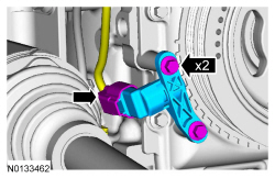
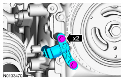
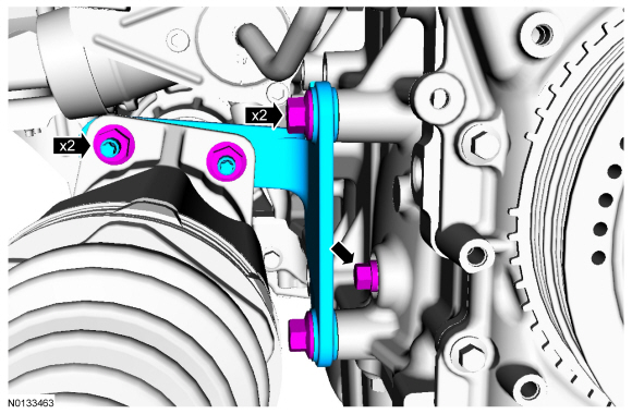
- Remove the 2 bolts, the 2 nuts and the RH halfshaft bracket.
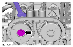
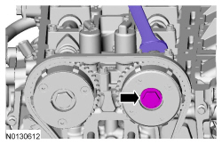
- Remove the engine plug bolt.

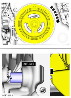
- Install the Crankshaft TDC Timing Peg.

- NOTE: The Crankshaft TDC Timing Peg will contact the crankshaft
and prevent it from turning past TDC. However, the crankshaft can still be
rotated in the counterclockwise direction. The crankshaft must remain at
the TDC position during the crankshaft pulley removal and installation.
NOTE: The engine front cover is shown removed in graphic for clarity.
Rotate the crankshaft slowly clockwise until the crankshaft contacts the Crankshaft TDC Timing Peg.
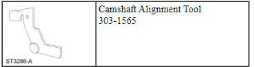
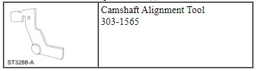
- NOTICE: The Camshaft Alignment Tool is for camshaft alignment
only. Using this tool to prevent engine rotation can result in engine
damage.
NOTE: The camshaft timing slots are offset. If the Camshaft Alignment Tool cannot be installed, remove the TDC Timing Peg and rotate the crankshaft three-fourths of a revolution clockwise and repeat the previous 2 steps of this procedure.
Install the Camshaft Alignment Tool into the rear of the intake camshaft slot as shown.

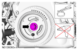
- NOTICE: The crankshaft must remain in the TDC position during
removal of the pulley bolt or damage to the engine can occur. Therefore, the
crankshaft pulley must be held in place with the Strap Wrench and the bolt
should be removed using an air impact wrench (1/2-in drive minimum).
NOTE: The crankshaft sprocket diamond washer may come off with the crankshaft pulley.
Use a Strap Wrench to hold the crankshaft pulley. Use an air impact wrench to remove the crankshaft pulley bolt.- Remove and discard the crankshaft pulley bolt and washer.
- Remove the crankshaft pulley.
- If the diamond washer did not come off with the crankshaft pulley, remove the diamond washer.

Installation
- NOTICE: Before installation, clean and inspect the diamond
washer for any damage. If damaged is evident, replace the diamond washer. If
no damage, the diamond washer is to be reused. If the diamond washer is not
installed, engine damage may occur.
Install the diamond washer.
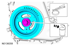
- NOTE: Apply clean engine oil on the seal contact area before
installing.
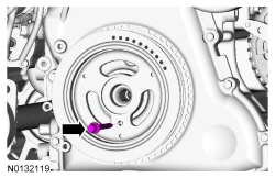
Position the crankshaft pulley onto the crankshaft and align the TDC guide hole at the 6 o'clock position.
- NOTE: This step will correctly align the crankshaft pulley to the
crankshaft.
Install a standard bolt through the crankshaft pulley TDC guide hole and into the engine front cover guide hole.
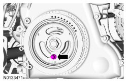
- NOTICE: The crankshaft must remain in the TDC position during
installation of the pulley bolt or damage to the engine can occur.
Therefore, the crankshaft pulley must be held in place with the Strap Wrench
and the bolt should be installed using hand tools only.
Install a new crankshaft pulley bolt. Use a Strap Wrench to hold the crankshaft pulley and tighten the crankshaft pulley bolt in 2 stages:
- Stage 1: Tighten to 100 Nm (74 lb-ft).
- Stage 2: Tighten an additional 90 degrees.
- Remove the bolt.
- NOTE: Do not tighten the CKP sensor bolts at this time.
Install the CKP sensor and the 2 bolts.
- Install the Crankshaft Sensor Alignment Tool onto the CKP sensor and the
tooth of the crankshaft pulley trigger wheel.
- Tighten the 2 bolts to 7 Nm (62 lb-in).
- Connect the CKP sensor electrical connector.
- Remove the Crankshaft TDC Timing Peg.
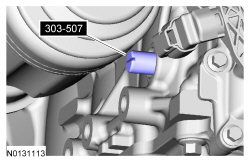
- Install the engine plug bolt and tighten to 20 Nm (177 lb-in).
- Install the RH halfshaft bracket, the 2 bolts and the 2 nuts.
- Tighten to 25 Nm (18 lb-ft).
- Install the RH halfshaft bracket, the 2 bolts and the 2 nuts.
- Remove the Camshaft Alignment Tool.
- Using a wrench on the flats of the intake camshaft to prevent cam
rotation, install the brake vacuum pump adapter.
- Tighten to 63 Nm (46 lb-ft).
- NOTE: The intake camshaft rear bearing cap must be secured within
10 minutes of Gasket Maker application. If the bearing cap is not secured
within 10 minutes, the sealant must be removed and the sealing area cleaned
with Motorcraft Metal Surface Prep.
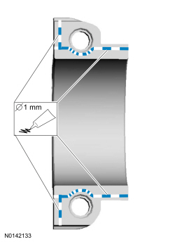
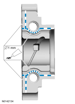
Apply 1 mm (0.039 in) beads of Gasket Maker to the intake rear camshaft bearing cap mating surface as shown.
- NOTICE: Wipe off any excess sealer from the vacuum pump
sealing surface of the cylinder head and camshaft cap.
Install the rear intake camshaft cap and the 2 bolts. Tighten the bolts in 2 stages:
- Stage 1: Tighten the bolts to 7 Nm (62 lb-in).
- Stage 2: Tighten the bolts to 16 Nm (142 lb-in).
- Install the valve cover. For additional information, refer to Valve Cover in this section.
- Install the brake vacuum pump. For additional information, refer to Section 206-07.
- Install the accessory drive belt. For additional information, refer to Section 303-05.
- Install the underbody shield and tighten the 4 retainers.

- Install the RH fender splash shield. For additional information, refer to Section 501-02.
- After completing the repairs, use the scan tool to perform the Misfire Monitor Neutral Profile Correction procedure, following the on-screen instructions.
Crankshaft Front Seal
Special Tool(s)
Material
Removal
NOTICE: Do not loosen or remove the crankshaft pulley bolt without first installing the special tools as instructed in this procedure. The crankshaft pulley and the crankshaft timing sprocket are not keyed to the crankshaft. The crankshaft, the crankshaft sprocket and the pulley are fitted together by friction, using diamond washers between the flange faces on each part. For that reason, the crankshaft sprocket is also unfastened if the pulley bolt is loosened. Before any repair requiring loosening or removal of the crankshaft pulley bolt, the crankshaft and camshafts must be locked in place by the special service tools, otherwise severe engine damage can occur.
NOTICE: During engine repair procedures, cleanliness is extremely important. Any foreign material, including any material created while cleaning gasket surfaces, that enters the oil passages, coolant passages or the oil pan can cause engine failure.
- Remove the crankshaft pulley. For additional information, refer to Crankshaft Pulley in this section.
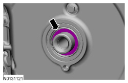
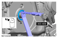
- NOTICE: Use care not to damage the engine front cover or the
crankshaft when removing the seal.
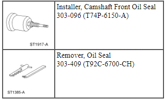
Using the Oil Seal Remover, remove the crankshaft front oil seal.
Installation
- NOTE: Remove the through-bolt from the Camshaft Front Oil Seal
Installer.
NOTE: Lubricate the oil seal with clean engine oil.
Using the Camshaft Front Oil Seal Installer, install the crankshaft front oil seal.
- Install the crankshaft pulley. For additional information, refer to Crankshaft Pulley in this section.
Engine Front Cover
Material
Removal
NOTICE: Do not loosen or remove the crankshaft pulley bolt without first installing the special tools as instructed in this procedure. The crankshaft pulley and the crankshaft timing sprocket are not keyed to the crankshaft. The crankshaft, the crankshaft sprocket and the pulley are fitted together by friction, using diamond washers between the flange faces on each part. For that reason, the crankshaft sprocket is also unfastened if the pulley bolt is loosened. Before any repair requiring loosening or removal of the crankshaft pulley bolt, the crankshaft and camshafts must be locked in place by the special service tools, otherwise severe engine damage can occur.
NOTICE: During engine repair procedures, cleanliness is extremely important. Any foreign material, including any material created while cleaning gasket surfaces, that enters the oil passages, coolant passages or the oil pan can cause engine failure.
- With the vehicle in NEUTRAL, position it on a hoist. For additional information, refer to Section 100-02.
- Release the fuel system pressure. For additional information, refer to Section 310-00.
- Remove the CAC inlet tube.

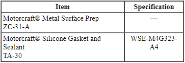
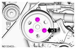
- Loosen the 3 coolant pump pulley bolts.

- Remove the accessory drive belt and tensioner. For additional information, refer to Section 303-05.
- Remove the crankshaft front seal. For additional information, refer to Crankshaft Front Seal in this section.
- Remove the engine mount. For additional information, refer to Engine Mount.
- Remove the 3 bolts and the coolant pump pulley.
- Remove the nut and the ground strap.
- Detach the 2 wiring harness retainers from the engine front cover.

- NOTICE: Do not use metal scrapers, wire brushes, power
abrasive disks or other abrasive means to clean sealing surfaces. These
tools cause scratches and gouges which make leak paths.
Remove the 21 bolts, the stud bolt and the engine front cover.
- Clean and inspect the mounting surfaces of the engine and the front cover.
Installation
- NOTE: The engine front cover must be secured within 10 minutes of
Silicone Gasket and Sealant application. If the valve cover is not secured
within 10 minutes, the sealant must be removed and the sealing area cleaned
with Motorcraft Metal Surface Prep.
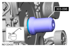
Apply a 3 mm (0.118 in) bead of Silicone Gasket and Sealant to the sealing surface of the front cover.
- Apply a 2 mm (0.078 in) bead of Silicone Gasket and Sealant to the 5 center sealing surfaces of the front cover.
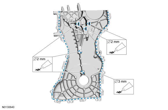
- NOTE: The engine front cover must be secured within 10 minutes of
Silicone Gasket and Sealant application. If the valve cover is not secured
within 10 minutes, the sealant must be removed and the sealing area cleaned
with Motorcraft Metal Surface Prep.
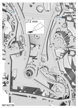
Apply beads of silicone gasket and sealant that are 2 mm (0.078 in) in diameter and 5 mm (0.19 in) in length across the cylinder head and cylinder block joint areas.
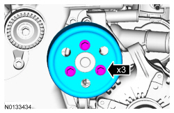
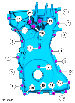
- Install the engine front cover, the 21 bolts and the stud bolt.
- Tighten in the sequence shown as follows:
- Tighten 1 through 19 to 10 Nm (89 lb-in).
- Tighten 20 through 22 to 48 Nm (35 lb-ft).
- Tighten in the sequence shown as follows:
- Attach the 2 wiring harness retainers to the engine front cover.
- Install the ground strap and nut.
- Tighten to 9 Nm (80 lb-in).
- Install the ground strap and nut.

- Install the coolant pump pulley and the 3 bolts.

- Install the engine mount. For additional information, refer to Engine Mount.
- Install the crankshaft front seal. For additional information, refer to Crankshaft Front Seal in this section.
- Install the accessory drive belt and tensioner. For additional information, refer to Section 303-05.
- Tighten the 3 coolant pump pulley bolts to 20 Nm (177 lb-in).
- Install the CAC inlet tube.
Timing Drive Components
Special Tool(s)
Removal
NOTICE: Do not loosen or remove the crankshaft pulley bolt without first installing the special tools as instructed in this procedure. The crankshaft pulley and the crankshaft timing sprocket are not keyed to the crankshaft. The crankshaft, the crankshaft sprocket and the pulley are fitted together by friction, using diamond washers between the flange faces on each part. For that reason, the crankshaft sprocket is also unfastened if the pulley bolt is loosened. Before any repair requiring loosening or removal of the crankshaft pulley bolt, the crankshaft and camshafts must be locked in place by the special service tools, otherwise severe engine damage can occur.
NOTICE: During engine repair procedures, cleanliness is extremely important. Any foreign material, including any material created while cleaning gasket surfaces, that enters the oil passages, coolant passages or the oil pan can cause engine failure.
- With the vehicle in NEUTRAL, position it on a hoist. For additional information, refer to Section 100-02.
- Remove the RH fender splash shield. For additional information, refer to Section 501-02.
- Remove the fuel injection pump and tappet. For additional information, refer to Section 303-04C.
- Using the crankshaft pulley bolt, rotate the engine clockwise until the fuel injection cam lobe is at zero lift.
- Remove the 4 stud bolts and the fuel injection pump housing.

- Remove the engine front cover. For additional information, refer to Engine Front Cover in this section.
- NOTICE: The Camshaft Alignment Tool is for camshaft alignment
only. Using this tool to prevent engine rotation can result in engine
damage.
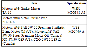
Install the Camshaft Alignment Tool into the rear of both of the camshaft slots as shown.
- Tighten the retainer.

- NOTICE: Do not rely on the Camshaft Alignment Tool to prevent
camshaft rotation. Damage to the tool or the camshaft can occur.
Using a wrench on the flats of the exhaust camshaft to prevent camshaft rotation, loosen the exhaust camshaft phaser and sprocket bolt.
- NOTICE: The Camshaft Alignment Tool is for camshaft alignment
only. Using this tool to prevent engine rotation can result in engine
damage.
Using a wrench on the flats of the intake camshaft to prevent camshaft rotation, loosen the intake camshaft phaser and sprocket bolt.

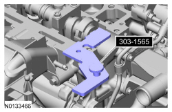
- Compress the timing chain tensioner in the following sequence.
- Using a small pick, release and hold the ratchet mechanism.
- While holding the ratchet mechanism in the released position, compress the tensioner by pushing the timing chain arm toward the tensioner.
- Insert a paper clip into the hole to retain the tensioner.
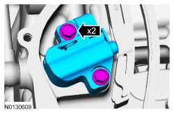
- Remove the 2 bolts and the timing chain tensioner.
- Remove the timing chain tensioner arm.
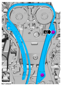
- Remove the 2 bolts and the timing chain guide.
- Remove the timing chain.
Installation
- Install the timing chain onto the 2 camshaft phaser and sprockets and
the crankshaft sprocket.
- Install the timing chain guide and the 2 bolts.
- Tighten to 10 Nm (89 lb-in).
- Install the timing chain arm.
- Install the timing chain guide and the 2 bolts.

NOTE: If the timing chain tensioner plunger and ratchet assembly are not pinned in the compressed position, follow the next 4 steps.
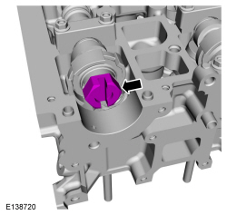
- NOTICE: Do not compress the ratchet assembly. This will damage
the ratchet assembly.
Using the edge of a vise, compress the timing chain tensioner plunger.
- Using a small pick, push back and hold the ratchet mechanism.
- While holding the ratchet mechanism, push the ratchet arm back into the tensioner housing.
- Install a paper clip into the hole in the tensioner housing to hold the ratchet assembly and the plunger in during installation.
- Install the timing chain tensioner and the 2 bolts.
- Tighten to 10 Nm (89 lb-in).
- Remove the paper clip to release the piston.
- NOTICE: Do not rely on the Camshaft Alignment Tool to prevent
camshaft rotation. Damage to the tool or the camshaft can occur.
Using a wrench on the flats of the exhaust camshaft to prevent camshaft rotation, tighten the exhaust camshaft phaser and sprocket bolt.
- Stage 1: Tighten to 40 Nm (30 lb-ft).
- Stage 2: Tighten an additional 60 degrees.

- NOTICE: The Camshaft Alignment Tool is for camshaft alignment
only. Using this tool to prevent engine rotation can result in engine
damage.
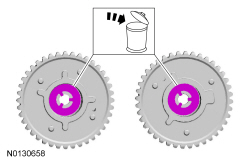
Using a wrench on the flats of the intake camshaft to prevent camshaft rotation, tighten the intake camshaft phaser and sprocket bolt.
- Stage 1: Tighten to 40 Nm (30 lb-ft).
- Stage 2: Tighten an additional 60 degrees.
- Install the front cover. For additional information, refer to Engine Front Cover in this section.
- Using the crankshaft pulley bolt, rotate the engine clockwise until the fuel injection cam lobe is at zero lift.
- Inspect the fuel injection pump housing gasket and replace as necessary.
- Install the fuel injection pump housing and the 4 bolts.
- Tighten to 15 Nm (133 lb-in) plus an additional 60 degrees.
- Install the tappet and fuel injection pump. For additional information, refer to Section 303-04C.
- Install the RH fender splash shield. For additional information, refer to Section 501-02.
Camshafts
Special Tool(s)
Material
Removal
NOTICE: During engine repair procedures, cleanliness is extremely important. Any foreign material (including any material created while cleaning gasket surfaces) that enters the oil passages, coolant passages or the oil pan can cause engine failure.
NOTICE: Do not rotate the camshafts unless instructed to in this procedure. Rotating the camshafts or crankshaft with timing components loosened or removed can cause serious damage to the valves and pistons.
- With the vehicle in NEUTRAL, position it on a hoist. For additional information, refer to Section 100-02.
- Check the valve clearance. For additional information, refer to Valve Clearance Check in this section.
- Remove the camshaft phaser and sprockets. For additional information, refer to Camshaft Phaser and Sprocket in this section.
- NOTICE: The Camshaft Alignment Tool is for camshaft alignment
only. Using this tool to prevent engine rotation can result in engine
damage.
Remove the Camshaft Alignment Tool from the rear of both of the camshaft slots.
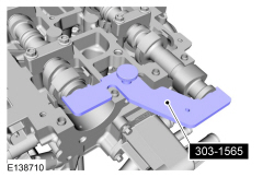
- Remove the 2 bolts and the 2 VCT solenoids.
- Remove the 3 bolts and the front camshaft bearing cap.
- NOTICE: Failure to follow the camshaft loosening procedure can
result in damage to the camshafts.
NOTE: Note the position of the camshaft lobes on the No. 1 cylinder for installation reference.
NOTE: Mark the location and orientation of each camshaft bearing cap.
Remove the camshafts from the engine.- Loosen the camshaft bearing caps in sequence 2 turns at a time until all tension is released from the camshaft bearing caps.
- Remove the camshaft bearing caps.
- Remove the camshafts.

Installation
- NOTE: The exhaust camshaft rear bearing cap must be secured
within 10 minutes of Gasket Maker application. If the bearing cap is not
secured within 10 minutes, the sealant must be removed and the sealing area
cleaned with Motorcraft Metal Surface Prep.
NOTE: Do not allow Gasket Maker to enter the camshaft bearing journal. If Gasket Maker is applied to the camshaft bearing journal, the journal and sealing area must be cleaned with Motorcraft Metal Surface Prep.
Apply 1 mm (0.039 in) beads of Gasket Maker to the exhaust rear camshaft bearing cap as shown.
- NOTICE: Install the camshafts with the alignment slots in the
camshafts lined up so the Camshaft Alignment Plate can be installed without
rotating the camshafts. Make sure the lobes on the No. 1 cylinder are in the
same position as noted in the removal procedure. Rotating the camshafts when
the timing chain is removed, or installing the camshafts 180 degrees out of
position can cause severe damage to the valves and pistons.
NOTICE: Failure to follow the camshaft tightening procedure can result in damage to the camshafts.
NOTICE: Wipe off any excess sealer from the fuel injection pump housing sealing surface of the cylinder head and rear camshaft cap.
NOTE: Lubricate the camshaft journals and camshaft bearing caps with clean engine oil.
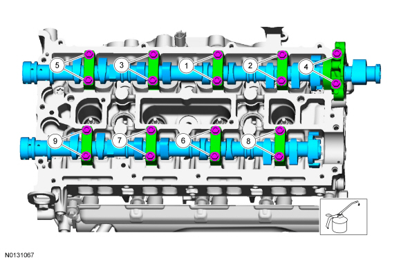
Install the camshafts and bearing caps in their original location and orientation. Tighten the camshaft bearing caps 2 turns at a time in the sequence shown in 2 stages:- Stage 1: Tighten to 7 Nm (62 lb-in).
- Stage 2: Tighten to 16 Nm (142 lb-in).
- NOTE: Lubricate the camshaft journals and the front camshaft
bearing cap with clean engine oil.
Install the front camshaft bearing cap and the 3 bolts. Tighten in the sequence shown in 2 stages:
- Stage 1: Tighten to 7 Nm (62 lb-in).
- Stage 2: Tighten to 16 Nm (142 lb-in).
- Install the 2 VCT solenoids and the 2 bolts.
- Tighten to 10 Nm (89 lb-in).

- NOTICE: The Camshaft Alignment Tool is for camshaft alignment
only. Using this tool to prevent engine rotation can result in engine
damage.
Install the Camshaft Alignment Tool into the rear of both of the camshaft slots as shown.
- Tighten the retainer.

- Install the camshaft phaser and sprockets. For additional information, refer to Camshaft Phaser and Sprocket in this section.
Camshaft Phaser and Sprocket
Removal
NOTICE: During engine repair procedures, cleanliness is extremely important. Any foreign material, including any material created while cleaning gasket surfaces, that enters the oil passages, coolant passages or the oil pan can cause engine failure.
- Remove the timing drive components. For additional information, refer to Timing Drive Components.
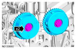
- Remove the 2 bolts and the intake and exhaust camshaft phaser and sprockets.

- NOTE: Washers are not required for installation of the VCT units.
If equipped, discard the washers.
Installation
- NOTE: Do not tighten the camshaft phaser and sprocket bolts at
this time. The bolts will be tightened during the timing drive component
installation procedure.
Install the intake and exhaust camshaft phaser and sprockets.
- Install the 2 bolts finger-tight.
- Install the timing drive components. For additional information, refer to Timing Drive Components.
Valve Tappets
Material
Removal and Installation
NOTICE: During engine repair procedures, cleanliness is extremely important. Any foreign material, including any material created while cleaning gasket surfaces, that enters the oil passages, coolant passages or the oil pan can cause engine failure.
NOTE: Removal steps in this procedure may contain installation details.
- With the vehicle in NEUTRAL, position it on a hoist. For additional information, refer to Section 100-02.
- Remove the camshafts. For additional information, refer to Camshafts in this section.
- NOTE: If the camshafts and valve tappets are to be reused, mark
the location of the valve tappets to make sure they are assembled in their
original positions.
NOTE: Lubricate the valve tappets with clean engine oil prior to installing.
Remove the 16 valve tappets.
- NOTE: The number on the valve tappets only reflects the digits
that follow the decimal. For example, a tappet with the number 0.650 has the
thickness of 3.650 mm.
Inspect the valve tappets. For additional information, refer to Section 303-00.
- To install, reverse the removal procedure.
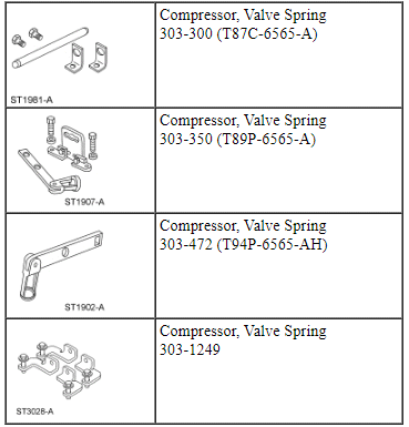
Valve Springs
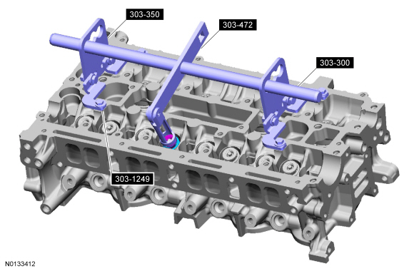
Special Tool(s)
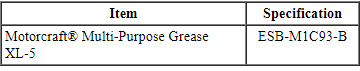
Material
Removal
NOTICE: During engine repair procedures, cleanliness is extremely important. Any foreign material, including any material created while cleaning gasket surfaces, that enters the oil passages, coolant passages or the oil pan can cause engine failure.
NOTE: If the parts are to be reused, mark the location to make sure they are assembled in their original positions.
- With the vehicle in NEUTRAL, position it on a hoist. For additional information, refer to Section 100-02.
- Remove the valve tappets. For additional information, refer to Valve Tappets in this section.
- Remove the spark plugs. For additional information, refer to Section 303-07C.
- NOTICE: Use compressed air at 7 to 10 bars (100-150 psi). Do
not disconnect the compressed air from the cylinder until the valve spring,
valve spring retainer and valve collet is installed. Any loss of air
pressure will allow the valve to fall into the cylinder.
Connect a compressed air supply to the cylinder that is being serviced.
- Using the Valve Spring Compressors, compress the valve spring and remove the valve collet, using some multi-purpose grease and a small screwdriver.
- Remove the valve spring retainer and the valve spring.

Installation
- NOTE: Check the seating of the valve collet.
Install the valve spring and the valve spring retainer.
- Compress the valve spring and install the valve collet using some grease and a small screwdriver.
- Disconnect the compressed air supply.
- Repeat the appropriate removal and installation steps for all of the other cylinders requiring service.
- Install the spark plugs. For additional information, refer to Section 303-07C.
- Install the valve tappets. For additional information, refer to Valve Tappets in this section.
Valve Seals
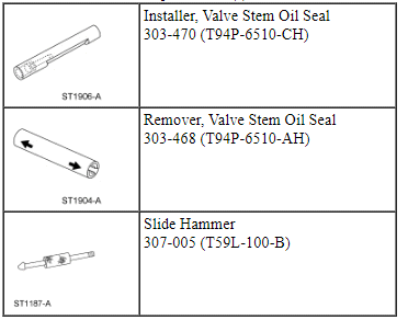
Special Tool(s)
Material
Removal
NOTICE: During engine repair procedures, cleanliness is extremely important. Any foreign material, including any material created while cleaning gasket surfaces, that enters the oil passages, coolant passages or the oil pan can cause engine failure.
- Remove the valve spring. For additional information, refer to Valve Springs in this section.
- Remove and discard the valve seal.
- Position the Valve Stem Oil Seal Remover and Slide Hammer over the seal.
- Pull up on the Slide Hammer and Valve Stem Oil Seal Remover and remove the seal.
Installation
- NOTE: Lubricate the valve seal with clean engine oil prior to
installing.
Using the Valve Stem Oil Seal Installer, install the valve seal.
- Install the valve spring. For additional information, refer to Valve Springs in this section.
Cylinder Head
Material
Removal
NOTICE: Do not loosen or remove the crankshaft pulley bolt without first installing the special tools as instructed in this procedure. The crankshaft pulley and the crankshaft timing sprocket are not keyed to the crankshaft. The crankshaft, the crankshaft sprocket and the pulley are fitted together by friction, using diamond washers between the flange faces on each part. For that reason, the crankshaft sprocket is also unfastened if the pulley bolt is loosened. Before any repair requiring loosening or removal of the crankshaft pulley bolt, the crankshaft and camshafts must be locked in place by the special service tools, otherwise severe engine damage can occur.
NOTICE: During engine repair procedures, cleanliness is extremely important. Any foreign material, including any material created while cleaning gasket surfaces, that enters the oil passages, coolant passages or the oil pan can cause engine failure.
- With the vehicle in NEUTRAL, position it on a hoist. For additional information, refer to Section 100-02.
- Release the fuel system pressure. For additional information, refer to Section 310-00.
- Remove the turbocharger. For additional information, refer to Section 303-04E.
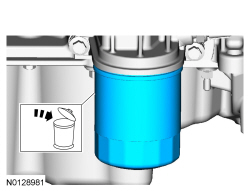
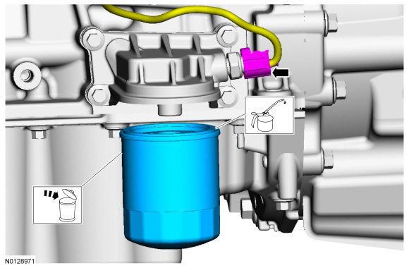
- Remove and discard the engine oil filter.
- Remove the fuel injectors. For additional information, refer to Section 303-04C.
- Remove the camshafts. For additional information, refer to Camshafts in this section.
- Remove the bolt and ground wire from the cylinder head.
- Disconnect the 4 coolant hoses from the coolant outlet.
- Disconnect the ECT sensor electrical connector.
- Slide the insulator up and disconnect the CHT electrical connector.
- NOTE: If the camshafts and valve tappets are to be reused, mark
the location of the valve tappets to make sure they are assembled in their
original positions.
Remove the 16 valve tappets.
- NOTE: The number on the valve tappets only reflects the digits
that follow the decimal. For example, a tappet with the number 0.650 has the
thickness of 3.650 mm.
Inspect the valve tappets. For additional information, refer to Section 303-00.
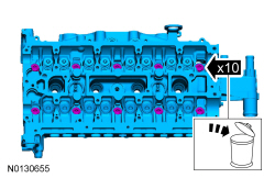
- Remove the 10 bolts and the cylinder head.
- Discard the bolts.
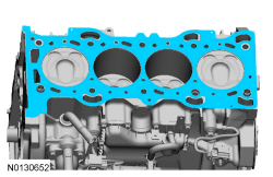
- Remove and discard the head gasket.
Installation
- NOTICE: Do not use metal scrapers, wire brushes, power
abrasive discs or other abrasive means to clean the sealing surfaces. These
tools cause scratches and gouges that make leak paths. Use a plastic
scraping tool to remove all traces of the head gasket.
NOTE: Observe all warnings or cautions and follow all application directions contained on the packaging of the silicone gasket remover and the metal surface prep.
NOTE: Clean the cylinder head bolt holes in the cylinder block. Make sure all coolant, oil or other foreign material is removed.
NOTE: If there is no residual gasket material present, metal surface prep can be used to clean and prepare the surfaces.
Clean the cylinder head and the cylinder block in the following sequence.- Remove any large deposits of silicone or gasket material with a plastic scraper.
- Apply silicone gasket remover, following package directions, and allow to set for several minutes.
- Remove the silicone gasket remover with a plastic scraper. A second application of silicone gasket remover may be required if residual traces of silicone or gasket material remain.
- Apply metal surface prep, following package directions, to remove any traces of oil or coolant, and to prepare the surfaces to bond with the new gasket. Do not attempt to make the metal shiny. Some staining of the metal surfaces is normal.
- Check the cylinder head distortion and the cylinder block distortion. For additional information, refer to Section 303-00.
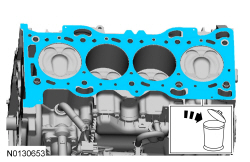
- Install a new cylinder head gasket.
- NOTE: The cylinder head bolts are torque-to-yield and must not be
reused. New cylinder head bolts must be installed.
Install the cylinder head and the 10 new bolts. Tighten the bolts in the sequence shown in 5 stages.
- Stage 1: Tighten to 7 Nm (62 lb-in).
- Stage 2: Tighten to 15 Nm (133 lb-in).
- Stage 3: Tighten to 55 Nm (41 lb-ft).
- Stage 4: Tighten 90 degrees.
- Stage 5: Tighten an additional 90 degrees.
- NOTE: Lubricate the valve tappets with clean engine oil prior to
installing.
Install the 16 valve tappets in their original positions.

- Connect the CHT electrical connector and slide the insulator down.
- Connect the 4 coolant hoses to the coolant outlet.
- Connect the ECT sensor electrical connector.

- Install the ground wire and bolt on the cylinder head.
- Tighten to 20 Nm (177 lb-in).

- Install the camshafts. For additional information, refer to Camshafts in this section.
- Install the fuel injectors. For additional information, refer to Section 303-04C.
- Remove the drain plug and drain the engine oil.
- Install the drain plug and tighten to 27 Nm (20 lb-ft).

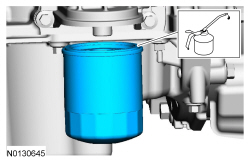
- NOTE: Lubricate the engine oil filter gasket with clean engine
oil prior to installing the oil filter.
Install a new engine oil filter.
- Tighten to 8 Nm (71 lb-in) plus an additional 180 degrees.
- Install the turbocharger. For additional information, refer to Section 303-04E.
- Fill the engine with clean engine oil.
Oil Pan
Material
Removal
- With the vehicle in NEUTRAL, position it on a hoist. For additional information, refer to Section 100-02.
- Remove the oil level indicator.

- Remove the engine ACL and ACL outlet pipe assembly. For additional information, refer to Section 303-12.
- Detach the 2 wiring harness retainers.
- NOTICE: To prevent damage to the transmission, do not loosen
the transmission-to-engine fasteners more than 5 mm (0.19 in).
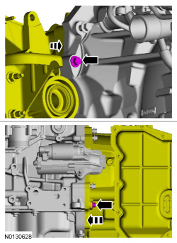
Loosen the 2 bolts and the 2 stud bolts 5 mm (0.19 in).
- Remove the engine roll restrictor. For additional information, refer to Section 307-01B.
- Remove the catalytic converter. For additional information, refer to Section 309-00.
- Remove the A/C drive belt. For additional information, refer to Section 303-05.
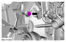
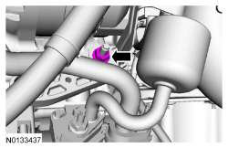
- Remove the A/C tube bracket nut.

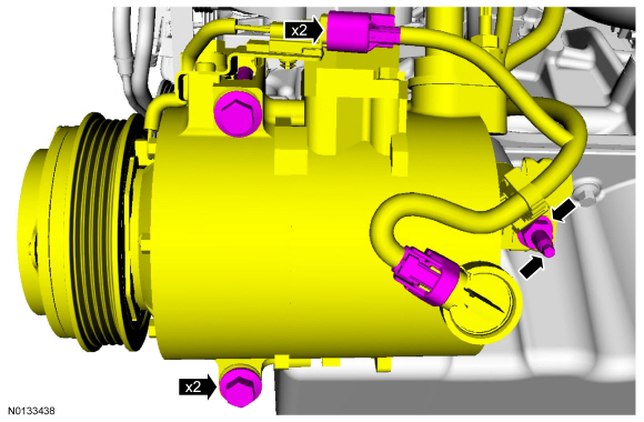
- Disconnect the 2 A/C compressor electrical connectors.
- Detach the wiring harness retainer from the A/C tube stud bolt.
- Remove the A/C compressor nut, stud and the 2 bolts.
- Position the A/C compressor aside and support with a length of mechanics wire.

- Loosen the 2 engine-to-bellhousing bolts 5 mm (0.19 in).
- Loosen the engine-to-bellhousing bolt 5 mm (0.19 in).
- Remove the 3 bellhousing-to-oil pan bolts.

- Remove the oil pan-to-bellhousing bolt.

- Separate the engine and transaxle 5 mm (0.19 in).
- Remove the drain plug and drain the engine oil.
- Install the drain plug and tighten to 27 Nm (20 lb-ft).
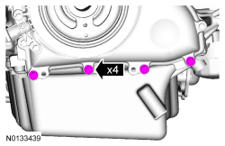
- Remove the 4 engine front cover-to-oil pan fasteners.

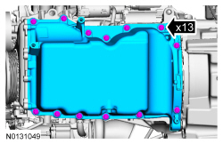
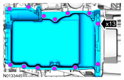
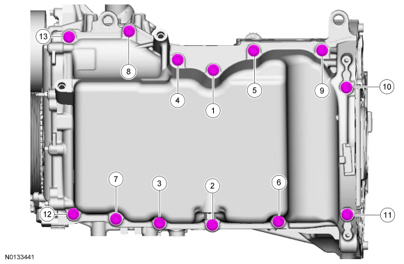
- Remove the 13 bolts and the oil pan.

Installation
- NOTICE: Do not use metal scrapers, wire brushes, power
abrasive discs or other abrasive means to clean the sealing surfaces. These
tools cause scratches and gouges, which make leak paths. Use a plastic
scraping tool to remove traces of sealant.
Clean and inspect all mating surfaces.
- NOTE: If the oil pan is not secured within 10 minutes of sealant
application, the sealant must be removed and the sealing area cleaned with
metal surface prep. Allow to dry until there is no sign of wetness, or 10
minutes, whichever is longer. Failure to follow this procedure can cause
future oil leakage.
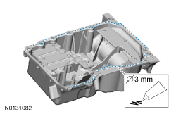
Apply a 3 mm (0.118 in) bead of silicone gasket and sealant to the oil pan-to-engine block and to the oil pan-to-engine front cover mating surface.

- Position the oil pan onto the engine and install the 13 oil pan bolts finger-tight.
- NOTE: The engine front cover-to-oil pan fasteners must be
tightened first to align the front surface of the oil pan flush with the
front surface of the engine block.
Install the 4 engine front cover-to-oil pan fasteners.
- Tighten to 10 Nm (89 lb-in).

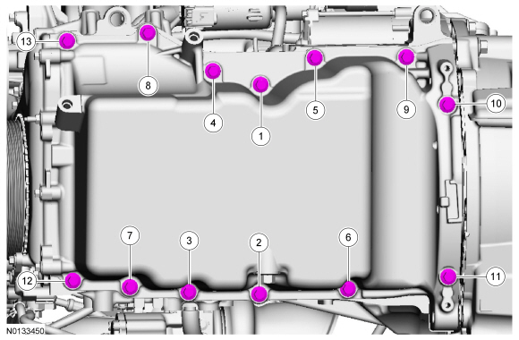
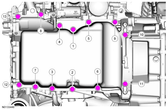
- Tighten the 13 oil pan bolts in the sequence shown.
- Tighten to 20 Nm (177 lb-in).
- Alternate tightening the LH bellhousing-to-engine and RH
engine-to-bellhousing lower bolts to draw the transaxle and engine together.
- Tighten to 48 Nm (35 lb-ft).
- Install the oil pan-to-bellhousing bolt.
- Tighten to 48 Nm (35 lb-ft).

- Tighten the engine-to-transaxle bolt to 48 Nm (35 lb-ft).
- Tighten the engine-to-transaxle bolt to 48 Nm (35 lb-ft).

- Install the 3 bellhousing-to-oil pan bolts.
- Tighten to 48 Nm (35 lb-ft).

- Install the A/C compressor, the 2 bolts and the stud.
- Tighten the bolts to 25 Nm (18 lb-ft) and the stud to 9 Nm (80 lb-in).
- Install the nut and tighten to 25 Nm (18 lb-ft).
- Connect the 2 A/C compressor electrical connectors.
- Install the A/C tube bracket nut.
- Tighten to 15 Nm (133 lb-in).
- Install the A/C drive belt. For additional information, refer to Section 303-05.
- Install the catalytic converter. For additional information, refer to Section 309-00.
- Install the engine roll restrictor. For additional information, refer to Section 307-01B.
- Tighten the bolt and the 2 stud bolts to 48 Nm (35 lb-ft).
- Attach the 2 wiring harness retainers.

- Install the engine ACL and ACL outlet pipe assembly. For additional information, refer to Section 303-12.
- Install the oil level indicator.
- Fill the engine with clean engine oil.
Oil Pump
Special Tool(s)
Material
Removal
- With the engine in NEUTRAL, position it on a hoist. For additional information, refer to Section 100-02.
- Remove the engine front cover. For additional information, refer to Engine Front Cover in this section.
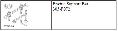
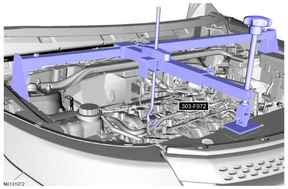
- Install the Engine Support Bar.
- Remove the A/C tube bracket nut.

- Disconnect the 2 A/C compressor electrical connectors.
- Detach the wiring harness retainer from the A/C tube stud bolt.
- Remove the A/C compressor nut, stud and the 2 bolts.
- Position the A/C compressor aside and support with a length of mechanics wire.

- Remove the drain plug and drain the engine oil.
- Install the drain plug and tighten to 27 Nm (20 lb-ft).

- Remove the 3 bellhousing-to-oil pan bolts.

- Remove the oil pan-to-bellhousing bolt.
- Remove the 13 bolts and the oil pan.

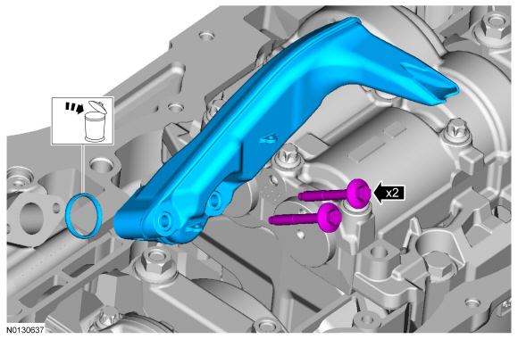
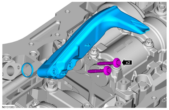
- Remove the 2 bolts and the oil pump screen and pickup tube.
- Discard the gasket.
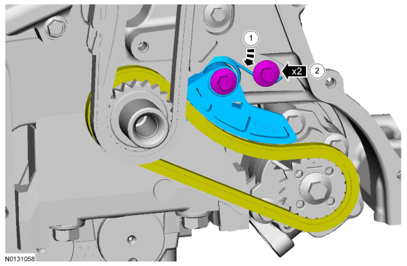
- Remove the oil pump drive chain tensioner.
- Push the tensioner spring down and release the spring from under the shoulder bolt.
- Remove the 2 shoulder bolts and the tensioner.
- Remove the chain from the oil pump sprocket.
- Remove the bolt and oil pump sprocket.
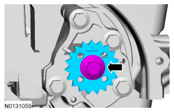
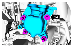
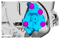
- Remove the 4 bolts and the oil pump.
Installation
- NOTE: Clean the oil pump and cylinder block mating surfaces with
metal surface prep.
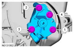
Install the oil pump assembly. Tighten the 4 bolts in the sequence shown in 2 stages:
- Stage 1: Tighten to 10 Nm (89 lb-in).
- Stage 2: Tighten to 20 Nm (177 lb-in).
- Install the oil pump sprocket and bolt.
- Tighten to 25 Nm (18 lb-ft).

- Install the chain on the oil pump sprocket.
- Install the tensioner and the 2 shoulder bolts.
- Tighten to 10 Nm (89 lb-in).
- Push the tensioner spring down and position the spring under the shoulder bolt.
- Install the tensioner and the 2 shoulder bolts.

- Install the oil pump screen and pickup tube and the 2 bolts.
- Tighten to 10 Nm (89 lb-in).
- NOTICE: Do not use metal scrapers, wire brushes, power
abrasive discs or other abrasive means to clean the sealing surfaces. These
tools cause scratches and gouges, which make leak paths. Use a plastic
scraping tool to remove traces to sealant.
Clean all the oil pan and cylinder block mating surfaces with metal surface prep.
- NOTE: If the oil pan is not secured within 10 minutes of sealant
application, the sealant must be removed and the sealing area cleaned with
metal surface prep. Allow to dry until there is no sign of wetness, or 10
minutes, whichever is longer. Failure to follow this procedure can cause
future oil leakage.
Apply a 3 mm (0.118 in) bead of silicone gasket and sealant to the oil pan-to-engine block mating surface.
- NOTE: Do not tighten the oil pan bolts at this time.
Position the oil pan onto the engine and install the 13 bolts finger-tight.
- Using a suitable straight edge, align the front surface of the oil pan flush with the front surface of the engine block.
- Tighten in the sequence shown to 20 Nm (177 lb-in).
- Install the oil pan-to-bellhousing bolt.
- Tighten to 48 Nm (35 lb-ft).

- Install the 3 bellhousing-to-oil pan bolts.
- Tighten to 48 Nm (35 lb-ft).
- Install the A/C compressor, the 2 bolts and the stud.
- Tighten the bolts to 25 Nm (18 lb-ft) and the stud to 9 Nm (80 lb-in).
- Install the nut and tighten to 25 Nm (18 lb-ft).
- Connect the 2 A/C compressor electrical connectors.

- Install the A/C tube bracket nut.
- Tighten to 15 Nm (133 lb-in).

- Using a floor jack and a wooden block, support the engine.
- Remove Engine Support Bar.
- Install the engine front cover. For additional information, refer to Engine Front Cover in this section.
- Fill the engine with clean engine oil.
Oil Pump Screen and Pickup Tube
Removal and Installation
NOTE: Removal steps in this procedure may contain installation details.
- With the vehicle in NEUTRAL, position it on a hoist. For additional information, refer to Section 100-02.
- Remove the oil pan. For additional information, refer to Oil Pan in this section.
- NOTE: A new gasket must be installed.
Remove the 2 bolts and the oil pump screen and pickup tube.
- Discard the gasket.
- To install, tighten to 10 Nm (89 lb-in).

- To install, reverse the removal procedure.
Oil Filter Adapter
Material
Removal and Installation
NOTE: Removal steps in this procedure may contain installation details.
- With the vehicle in NEUTRAL, position it on a hoist. For additional information, refer to Section 100-02.
- Disconnect the battery ground cable. For additional information, refer to Section 414-01.
- Loosen the 4 retainers and remove the underbody shield.

- NOTE: Lubricate the new engine oil filter gasket with clean
engine oil prior to installing the new oil filter.
Remove and discard the oil filter and gasket.
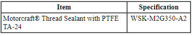
- Disconnect the EOP switch electrical connector.
- To install, tighten the new oil filter to 8 Nm (71 lb-in) plus an additional 180 degrees.
- NOTE: Install a new oil filter adapter gasket.
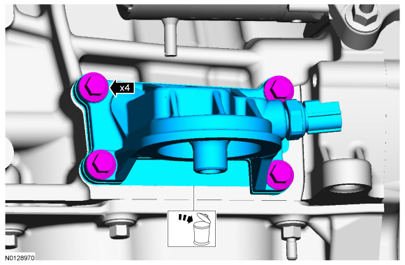
Remove the 4 bolts and the oil filter adapter.
- Discard the gasket.
- To install, tighten the oil filter adapter bolts to 25 Nm (18 lb-ft).
- To install, reverse the removal procedure.
Engine Oil Pressure (EOP) Switch
Material
Removal and Installation
NOTE: Removal steps in this procedure may contain installation details.
- With the vehicle in NEUTRAL, position it on a hoist. For additional information, refer to Section 100-02.
- Loosen the 4 retainers and remove the underbody shield.

- NOTE: Apply thread sealant to the EOP switch threads.
Disconnect the EOP switch electrical connector.
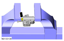
- Remove the EOP switch.
- To install, tighten to 15 Nm (133 lb-in).
- To install, reverse the removal procedure.
Flexplate
Special Tool(s)
Removal
- With the vehicle in NEUTRAL, position it on a hoist. For additional information, refer to Section 100-02.
- Remove the transaxle. For additional information, refer to Section 307-01B.
- NOTE: Do not reuse the flexplate bolts.
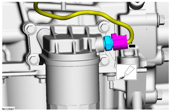
Install the Flywheel Holding Tool and remove the 6 bolts and the flexplate.
- Discard the bolts.
Installation
- NOTE: Special bolts are used for installation. Do not use
standard bolts.
Install the flexplate, the 6 new bolts and the Flywheel Holding Tool.
- Tighten in the sequence shown in 3 stages:
- Stage 1: Tighten to 50 Nm (37 lb-ft).
- Stage 2: Tighten to 80 Nm (50 lb-ft).
- Stage 3: Tighten to 112 Nm (83 lb-ft).
- Tighten in the sequence shown in 3 stages:
- Install the transaxle. For additional information, refer to Section 307-01B.
- After completing the repairs, use the scan tool to perform the Misfire Monitor Neutral Profile Correction procedure, following the on-screen instructions.
Crankshaft Rear Seal with Retainer Plate
Special Tool(s)
Material
Removal
- With the vehicle in NEUTRAL, position it on a hoist. For additional information, refer to Section 100-02.
- Remove the oil level indicator.

- Remove the A/C drive belt. For additional information, refer to Section 303-05.
- Remove the flexplate. For additional information, refer to Flexplate in this section.
- Remove the A/C tube bracket nut.

- Disconnect the 2 A/C compressor electrical connectors.
- Detach the wiring harness retainer from the A/C tube stud bolt.
- Remove the A/C compressor nut, stud and the 2 bolts.
- Position the A/C compressor aside and support with a length of mechanics wire.

- Remove the drain plug and drain the engine oil.
- Install the drain plug and tighten to 27 Nm (20 lb-ft).

- Remove the 4 engine front cover-to-oil pan fasteners.

- Remove the 13 bolts and the oil pan.

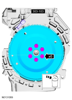
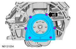
- Remove the 6 bolts and the crankshaft rear seal with retainer plate.
Installation
- NOTICE: Do not use metal scrapers, wire brushes, power
abrasive discs or other abrasive means to clean the sealing surfaces. These
tools cause scratches and gouges, which make leak paths. Use a plastic
scraping tool to remove traces of sealant.
Clean and inspect all the oil pan, cylinder block and front cover flange mating surfaces.
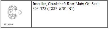
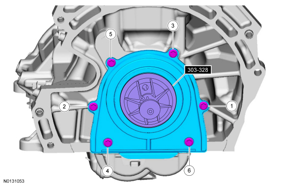
- Using the Crankshaft Rear Main Oil Seal Installer, position the
crankshaft rear oil seal with retainer plate onto the crankshaft.
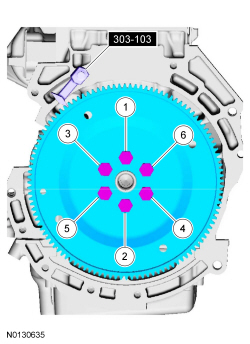
- Install the 6 bolts and tighten in the sequence shown to 10 Nm (89 lb-in).
- Remove the Crankshaft Rear Main Oil Seal Installer.
- NOTE: If the oil pan is not secured within 10 minutes of sealant
application, the sealant must be removed and the sealing area cleaned with
metal surface prep. Allow to dry until there is no sign of wetness, or 10
minutes, whichever is longer. Failure to follow this procedure can cause
future oil leakage.
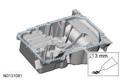
Apply a 3 mm (0.118 in) bead of silicone gasket and sealant to the oil pan-to-engine block and to the oil pan-to-engine front cover mating surface.
- Position the oil pan onto the engine and install the 13 oil pan bolts finger-tight.
- NOTE: The engine front cover-to-oil pan fasteners must be
tightened first to align the front surface of the oil pan flush with the
front surface of the engine block.
Install the 4 engine front cover-to-oil pan fasteners.
- Tighten to 10 Nm (89 lb-in).
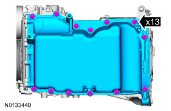
- Tighten the 13 oil pan bolts in the sequence shown.
- Tighten to 20 Nm (177 lb-in).
- Install the A/C compressor, the 2 bolts and the stud.
- Tighten the bolts to 25 Nm (18 lb-ft) and the stud to 9 Nm (80 lb-in).
- Install the nut and tighten to 25 Nm (18 lb-ft).
- Connect the 2 A/C compressor electrical connectors.

- Install the A/C tube bracket nut.
- Tighten to 15 Nm (133 lb-in).

- Install the flexplate. For additional information, refer to Flexplate in this section.
- Install the A/C drive belt. For additional information, refer to Section 303-05.
- Install the oil level indicator.

- Fill the engine with clean engine oil.
Engine Mount
Removal and Installation
NOTE: Removal steps in this procedure may contain installation details.
- With the vehicle in NEUTRAL, position it on a hoist. For additional information, refer to Section 100-02.
- Loosen the 4 retainers and remove the underbody shield.

- Detach the 2 wiring harness retainers from the valve cover stud bolts.
- Detach the CAC inlet pipe.
- Using a floor jack and a wooden block, support the engine.

- Remove the 4 nuts, the 3 bolts and the engine mount.
- To install, tighten the bolts to 90 Nm (66 lb-ft) and the nuts to 125 Nm (92 lb-ft).
- To install, reverse the removal procedure.
 General Procedures
Valve Clearance Check
Remove the RH fender splash shield. For additional information, refer
to Section 501-02.
Remove the valve cover. For additional information, refer to Valve
Cov ...
 Removal
Engine
Special Tool(s)
WARNING: Do not smoke, carry lighted tobacco or have an open flame of any
type when working on or near any fuel-related component. Highly flammable
mixtures are always prese ...
Other materials:
Disassembly and Assembly of Subassemblies
Cylinder Head
Special Tool(s)
Material
Disassembly
NOTICE: During engine repair procedures, cleanliness is extremely
important. Any foreign material, including any material created while cleaning
gasket surfaces, that enters the oil passages, coolant passages or the oil pan
can cause en ...
Diagnosis and Testing
Climate Control System
Special Tool(s)
Principles of Operation
For additional refrigerant system and component information, refer to Section
412-01.
Climate Control System Network Communication
The controls for the climate control system are in one or more locations
depending on vehicle opt ...
Trunk release
From Inside Your Vehicle
Press the button located on the instrument panel.
Vehicles with Intelligent Access
1. Unlock the trunk with the remote
control or power door lock control.
The trunk unlocks when you press the
release button if the intelligent access
transmitter is within 3 feet ...
