SPECIFICATIONS
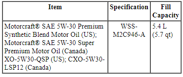
Material
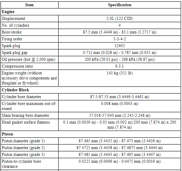
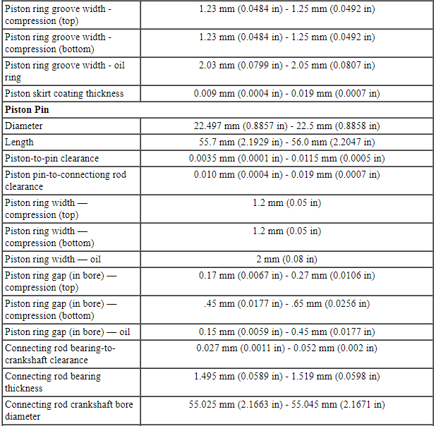
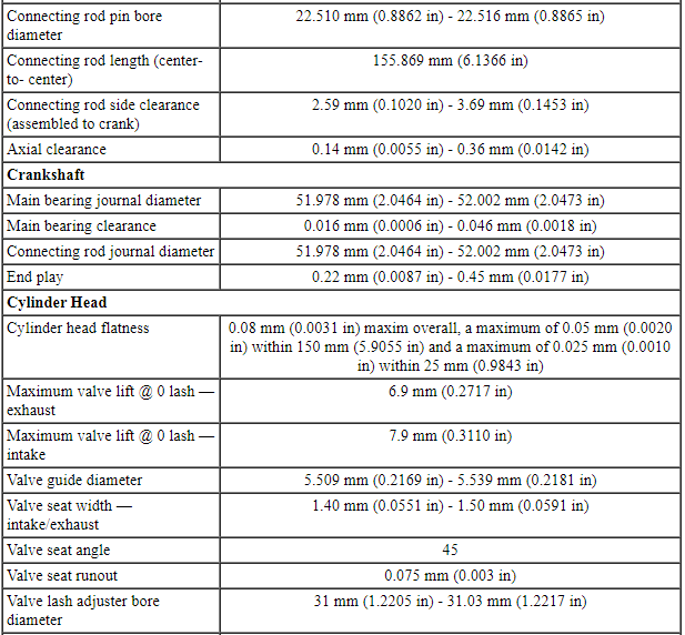
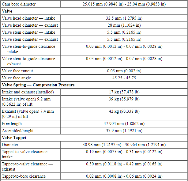
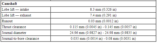
General Specifications
Torque Specifications
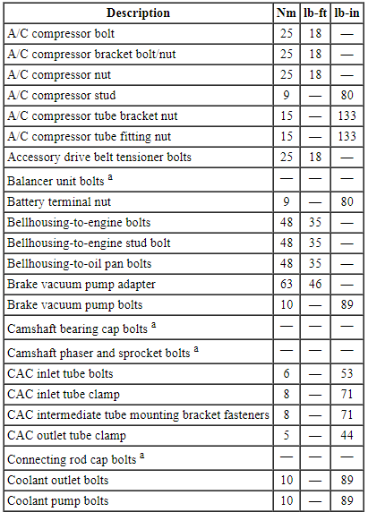
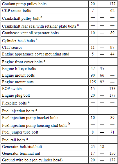
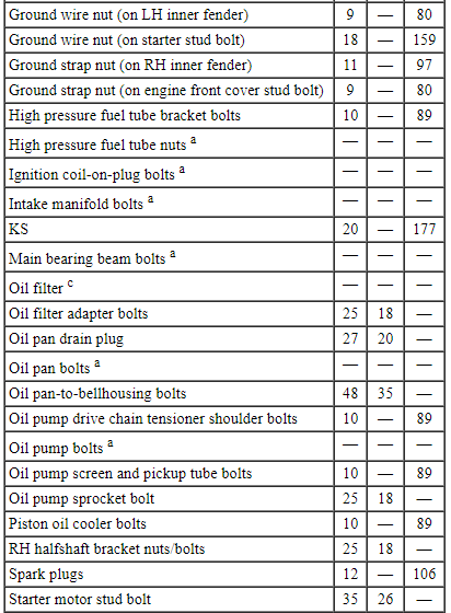
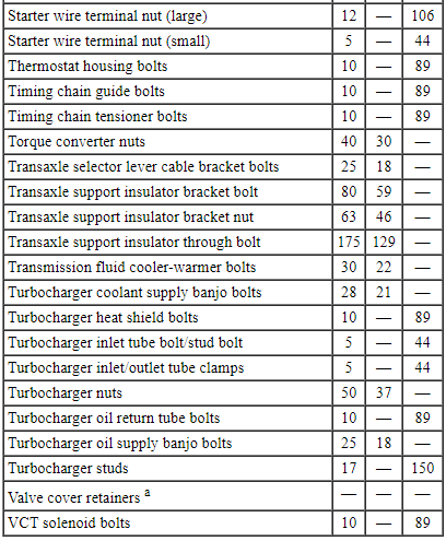
a Refer to the procedure in this section.
b 15 Nm plus an additional 60 degrees
c 8 Nm plus an additional 180 degrees
DESCRIPTION AND OPERATION
Engine
Overview
The 2.0L GTDI 4-cylinder engine has the following features:
- Dual overhead camshafts
- Four valves per cylinder
- Composite intake manifold
- Aluminum cylinder head
- Aluminum cylinder block
- GTDI
- Ti-VCT
- Electronic ignition system with coil-on-plug 4 ignition coils
Engine Identification
Always refer to these labels when installation of new parts is necessary or when checking engine calibrations. The engine parts often differ within a CID family. Verification of the identification codes will make sure the correct parts are obtained. These codes contain all the pertinent information relating to the dates, optional equipment and revisions.
Engine Code Information Label
The engine code information label, located on the front side of the valve cover, contains the following:
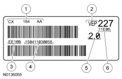
- Engine part numb
- Valencia Engine Plant
- Plant code
- Engine serial number
- Engine displacement
- Engine build date YYM(A-L)DD
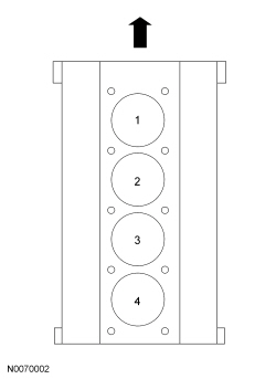
Engine Cylinder Identification
System Operation
Engine Oil Flow Illustration
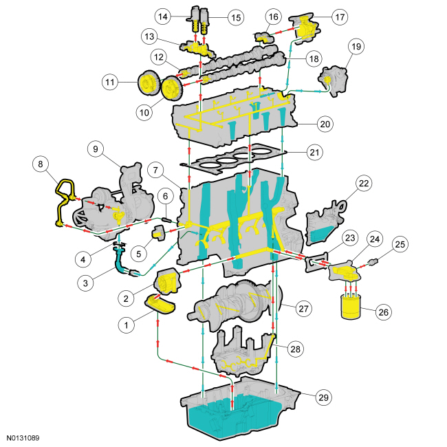
Lubrication System
The engine lubrication system is of the force-feed type in which oil is supplied under full pressure to the crankshaft, connecting rod bearings, timing chain tensioners, camshaft bearing caps and VCT solenoids. The flow of oil to the valve tappets and valve train is controlled by a restricting orifice located in the cylinder head gasket.
The lubrication system is designed to provide optimum oil flow to critical components of the engine through its entire operating range.
The heart of the system is a positive displacement internal gear oil pump.
Generically, this design is known as a gerotor pump, which operates as follows:
- The oil pump is chain driven off of the crankshaft.
- System pressure is limited by an integral, internally-vented relief valve which directs the bypassed oil back to the inlet side of the oil pump.
- Oil pump displacement has been selected to provide adequate volume to make sure of correct oil pressure both at hot idle and maximum speed.
- The relief valve calibration protects the system from excessive pressure during high-viscosity conditions.
- The relief valve is designed to provide adequate connecting rod bearing lubrication under high temperature and high-speed conditions.
Valve Train
The valve train uses DAMB. The camshaft lobes are positioned directly above mechanical buckets which are positioned on top of the valves.
Ti-VCT
The Ti-VCT system allows variable control of the valves which optimizes combustion at full load providing improved power and low speed torque (broadening the torque curve) which enables variable valve overlap which provides better fuel economy and emissions and provides optimized cold start operation with improved exhaust emissions.
DIAGNOSIS AND TESTING
Engine
Refer to Section 303-00 for basic mechanical concerns or refer to the Powertrain Control/Emissions Diagnosis (PC/ED) manual for driveability concerns.

 General Procedures
Valve Clearance Check
Remove the RH fender splash shield. For additional information, refer
to Section 501-02.
Remove the valve cover. For additional information, refer to Valve
Cov ...
Other materials:
Description and Operation
Instrument Panel Cluster (IPC)
Overview
Base IPC
Tachometer
Main menu navigation
Main menu text display
LH turn indicator
TPMS warning indicator
MIL
Stability-traction control indicator (sliding car icon)
Stability-traction control disabled indicator (sliding car OFF icon)
Air b ...
Head restraints
WARNING: To minimize the risk of neck injury in the event of a
crash, the driver and passenger occupants should not sit in or
operate the vehicle, until the head restraint is placed in its proper
position. The driver should never adjust the head restraint while the
vehicle is in motion.
WARNING ...
Removal and Installation
Antenna - Satellite Radio
Removal and Installation
NOTE: This procedure applies to both the stand-alone satellite radio
antenna and the combination satellite radio/Global Positioning System (GPS)
antenna.
Lower the headliner. For additional information, refer to Section
501-05.
...
