SPECIFICATIONS
Material
Torque Specifications
a Refer to the procedure in this section.
DESCRIPTION AND OPERATION
Fuel Charging and Controls
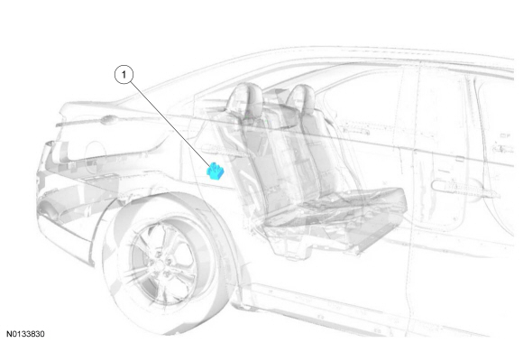
Component Locations
WARNING: Do not smoke, carry lighted tobacco or have an open flame of any type when working on or near any fuel-related component. Highly flammable mixtures are always present and may be ignited. Failure to follow these instructions may result in serious personal injury.
NOTICE: Handle the fuel injectors and fuel rail with extreme care to prevent damage to the fuel inlet of the fuel rail, fuel injector sealing areas, and sensitive fuel-metering orifices.
2.0L GTDI
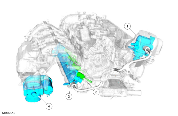
FPCM
System Operation
REFER to the PC/ED manual section 1 Description and Operation.
Component Description
REFER to the PC/ED manual section 1 Description and Operation.
DIAGNOSIS AND TESTING
Fuel Charging and Controls
For PCM DTCs, REFER to Section 303-14, PCM DTC Chart. For driveability symptoms without DTCs, refer to the Powertrain Control/Emissions Diagnosis (PC/ED) manual, section 3 Symptom Charts.
GENERAL PROCEDURES
Fuel Injection Pump Tappet Inspection
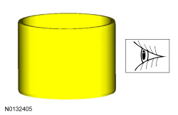
- Inspect the fuel injection pump tappet for flat spots or scoring, especially in the indicated areas. Visual check.
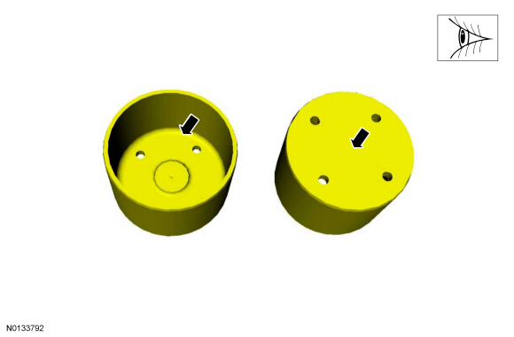
- If any damage is found, inspect the fuel injection pump and the fuel injection pump tappet drive lobe. Install new components as necessary.
REMOVAL AND INSTALLATION
Fuel Injectors
Removal and Installation
- The fuel injectors are serviced with the fuel rail, refer to Fuel Rail.
Fuel Rail
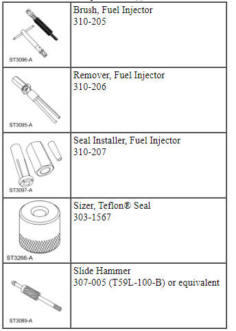
Special Tool(s)
Material
Removal
WARNING: Before beginning any service procedure in this section, refer to Safety Warnings in Section 100-00. Failure to follow this instruction may result in serious personal injury.
WARNING: Clean all fuel residue from the engine compartment. If not removed, fuel residue may ignite when the engine is returned to operation. Failure to follow this instruction may result in serious personal injury.
WARNING: Do not work on the fuel system until the pressure has been released and the engine has cooled. Fuel in the high-pressure fuel system is hot and under very high pressure. High-pressure fuel may cause cuts and contact with hot fuel may cause burns. Failure to follow these instructions may result in serious personal injury.
NOTE: A clean working environment is essential to prevent dirt or foreign material contamination.
- Release the fuel system pressure, refer to Section 310-00.
- Disconnect the battery ground cable, refer to Section 414-01.
- Remove the intake manifold, refer to Section 303-01C.
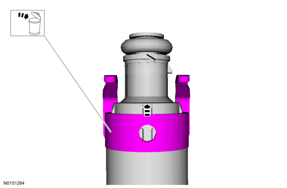
- NOTE: When removing or installing the fuel injection pump noise insulator, spreading the openings will reduce the risk of damage.

- NOTE: To release the fuel pressure in the high pressure fuel tube, wrap the fuel injection pump flare nut with a shop towel to absorb any residual fuel pressure during the loosening of the fuel injection pump flare nut.


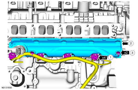
- NOTICE: Pull out the fuel rails in the direction of the fuel
injector axis or damage may occur to the fuel injectors.
NOTE: Use compressed air and remove any dirt or foreign material from the cylinder head, block and general surrounding area of the fuel rail and injectors.
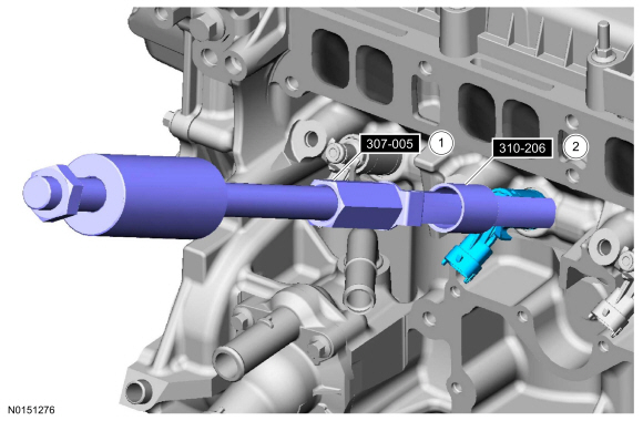
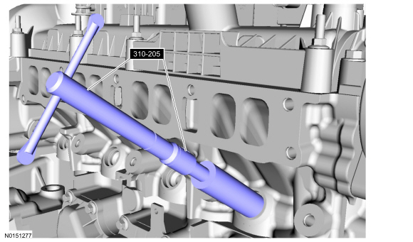
NOTE: When removing the fuel rails, the fuel injectors may remain in the cylinder head and require the use of a Fuel Injector Remover tool to extract.
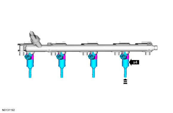
- Remove any of the fuel injectors that remained in the fuel rail.

- Using the Slide Hammer and the Fuel Injector Remover, remove the fuel
injectors that remained in the cylinder head.
- 307-005 (T59L-100-B) or equivalent.
- 310-206.
- NOTE: Make sure to thoroughly clean any residual fuel or foreign
material from the cylinder head, block and the general surrounding area of
the fuel rails and injectors.
NOTE: Do not use compressed air to clean the tip of the fuel injector.
NOTE: Do not use a brush to clean the tip of the fuel injector.
- 310-205.
Installation
NOTE: A clean working environment is essential to prevent dirt or foreign material contamination.
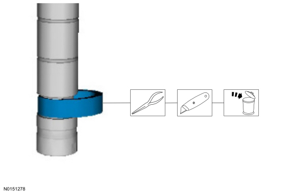
- NOTICE: Do not attempt to cut the lower Teflon seal without
first pulling it away from the fuel injector or damage to the injector may
occur.
NOTE: Use care when removing the lower Teflon seals, not to scratch, nick or gouge the fuel injectors.
- Pull the lower Teflon seal away from the injector.
- Carefully cut and discard the lower fuel injector Teflon seals.
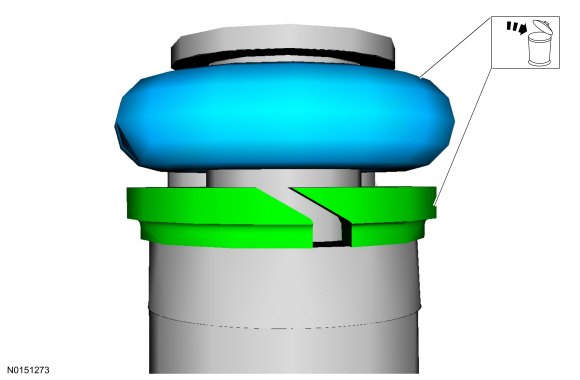
- NOTE: Do not lubricate the new lower Teflon fuel injector seals.
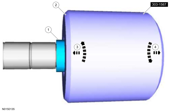
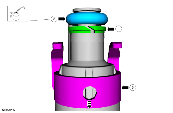
- Position the Teflon seal guide 310-207 (part of the Fuel Injector Seal Installer) on the tip of the fuel injector.
- NOTICE: Once the Teflon seal is installed on the Arbor,
it should immediately be installed onto the fuel injector to avoid
excessive expansion of the Teflon seal.
NOTE: Make sure that new lower fuel injector Teflon seals are installed.
- Using the Pusher Tool 310-207 (part of the Fuel Injector Seal Installer), slide the Teflon seals off of the Arbor and into the groove on the fuel injectors.
- NOTICE: Install the fuel injectors into the cylinder head
within 15 minutes of sizing the seals due to Teflon seal expansion.
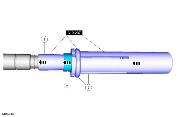
- NOTE: Make sure the Teflon seal is fully seated in the
groove on the fuel injector before sizing the Teflon seal.
Some Teflon seal massaging with your fingers before the Teflon seal sizer tool is installed will aid in installing the Teflon seal sizer tool.
- Position the Teflon seal sizer tool 303-1567 with the larger opening towards the Teflon seal. Push while turning the Teflon seal sizer tool 180 degrees. Special Tool(s): 303-1567.
- Once the Teflon seal sizer tool 303-1567 is installed, check and make sure the Teflon seal is in the sizing portion of the Teflon seal sizer tool. After one minute, turn the Teflon seal sizer tool back 180 degrees and remove.
- NOTE: Make sure the Teflon seal is fully seated in the
groove on the fuel injector before sizing the Teflon seal.
- NOTICE: Use new fuel injector O-ring seals that are made of
special fuel-resistant material. The use of ordinary O-ring seals may cause
the fuel system to leak. Do not reuse the O-ring seals.
NOTE: Do not lubricate the new lower Teflon fuel injector seals.
NOTE: Make sure that new upper fuel injector O-ring seals, new upper fuel injector O-ring seal support rings and new fuel injector retainer clips are installed.
Material: Motorcraft SAE 5W-30 Premium Synthetic Blend Motor Oil (US).
- NOTE: The anti-rotation finger of the fuel injector clip must
slip into the groove of the fuel rail cup.
NOTE: The fuel rail pressure sensor must be replaced if it is removed from the fuel rail, refer to Section 303-14.
- NOTE: Do not lubricate the new lower Teflon fuel injector seals.
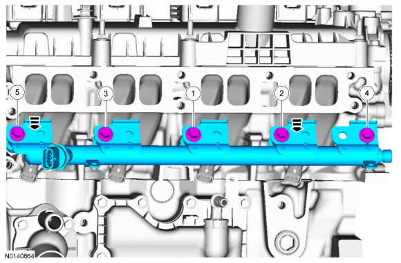
NOTE: Make sure that new fuel rail bolts are installed.
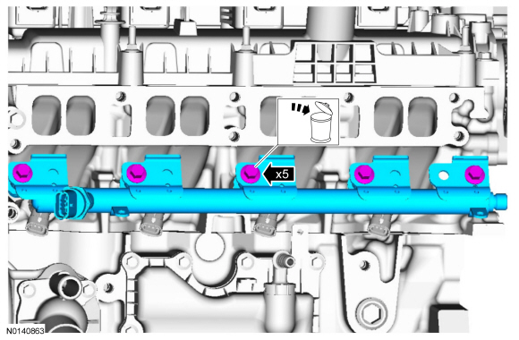
NOTE: Push down on the fuel rail face above the injectors.
Tighten the 5 fuel rail bolts in the following 2 stages.- Stage 1: Tighten to 8 Nm (71 lb-in) in the sequence shown.
- Stage 2: Tighten an additional 26 degrees in the sequence shown.
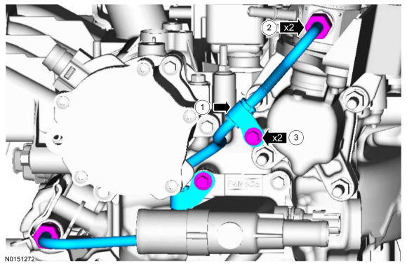
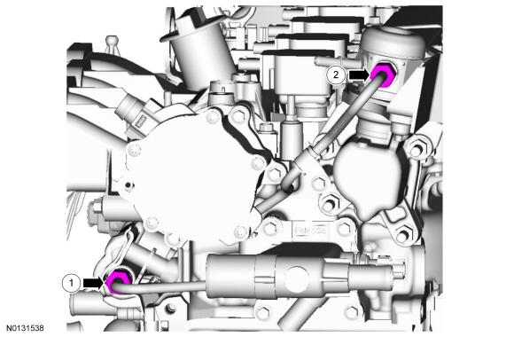
- NOTE: Only tighten the 2 high pressure fuel tube flare nuts
finger tight at this stage.
NOTE: Only tighten the 2 high pressure fuel tube bracket bolts finger tight at this stage.
- NOTE: Make sure that a new high pressure fuel tube is installed.
- NOTE: Calculate the correct torque wrench setting for the
following torque. Refer to the Torque Wrench Adapter Formulas in the
Appendix.
- Stage 1: Using a torque adapter, tighten to 15 Nm (133 lb-in).
- Stage 2: Tighten an additional 30 degrees.
- Tighten to 10 Nm (89 lb-in).
- NOTE: When removing or installing the fuel injection pump noise insulator, spreading the openings will reduce the risk of damage.

- Install the intake manifold, refer to Section 303-01C.
- Connect the battery ground cable, refer to Section 414-01.
- Pressurize the fuel system, refer to Section 310-00.
Fuel Injection Pump
Material
Removal
WARNING: Do not smoke, carry lighted tobacco or have an open flame of any type when working on or near any fuel-related component. Highly flammable mixtures are always present and may be ignited. Failure to follow these instructions may result in serious personal injury.
WARNING: Before working on or disconnecting any of the fuel tubes or fuel system components, relieve the fuel system pressure to prevent accidental spraying of fuel. Fuel in the fuel system remains under high pressure, even when the engine is not running. Failure to follow this instruction may result in serious personal injury.
WARNING: Clean all fuel residue from the engine compartment. If not removed, fuel residue may ignite when the engine is returned to operation. Failure to follow this instruction may result in serious personal injury.
WARNING: Always disconnect the battery ground cable at the battery when working on an evaporative emission (EVAP) system or fuel-related component. Highly flammable mixtures are always present and may be ignited. Failure to follow these instructions may result in serious personal injury.
NOTICE: Do not loosen any fittings or plugs on the fuel injection pump.
- Release the fuel system pressure, for additional information, refer to Section 310-00.
- Disconnect the battery ground cable, for additional information, refer to Section 414-01.
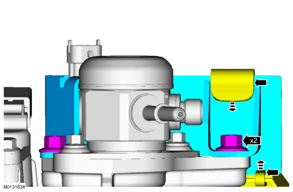
- NOTE: Use care when removing the fuel injection pump noise insulator. Spreading the openings will aid in removing the fuel injection pump noise insulator and reduce the risk of damage.

- Remove the ACL outlet pipe, for additional information, refer to Section 303-12.
- For additional information, refer to Section 310-00.
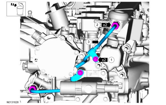
- NOTE: To release the fuel pressure in the high-pressure fuel
tube, wrap the fuel injection pump flare nut with a shop towel to absorb any
residual fuel pressure during the loosening of the fuel injection pump flare
nut.
NOTE: Make sure that a new high pressure fuel tube is installed.
Discard the specified component. Follow local disposal regulations.

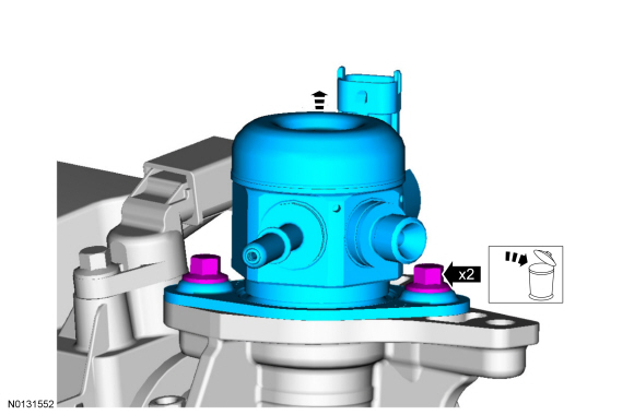
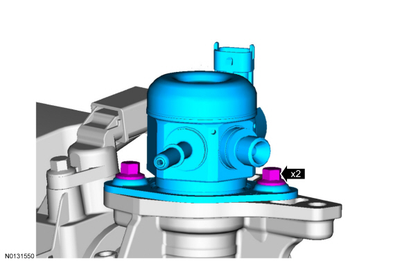
- NOTE: Make sure that new fuel injection pump bolts are installed.
Alternately loosen the 2 fuel injection pump bolts one complete revolution at a time. Discard the specified component. Follow local disposal regulations.
- Discard the specified component. Follow local disposal regulations.
Installation
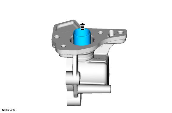
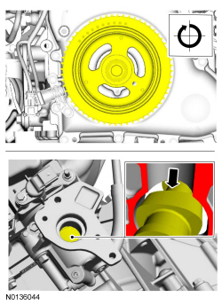
- Inspect the fuel injection pump tappet, for additional information, refer to Fuel Injection Pump Tappet Inspection in this section. Visual check.
- NOTICE: Only rotate the crankshaft clockwise or damage to the
engine may occur.
NOTE: The cam lobe for the fuel injection pump must be at Bottom Dead Center (BDC) for the fuel injection pump installation.
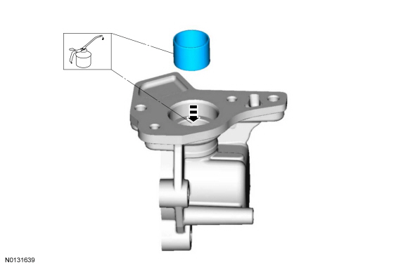
- NOTE: Apply clean engine oil to the fuel injection pump tappet
and to the fuel injection pump cover bore.
Apply the specified lubricant to the specified component.
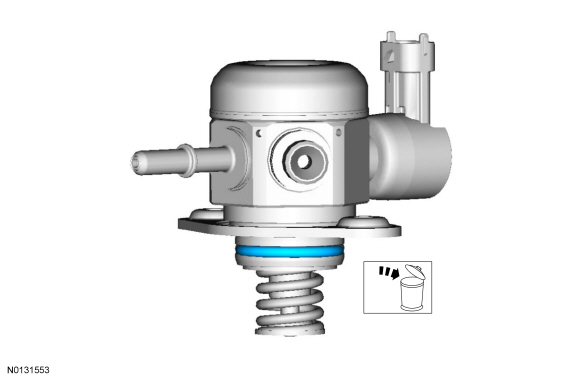
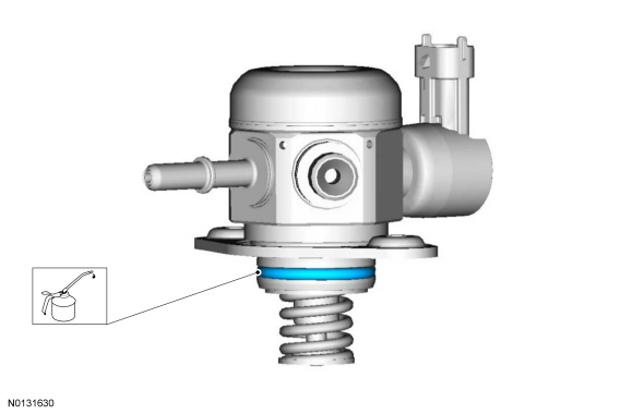
- NOTE: Make sure that a new fuel injection pump O-ring seal is
installed.
NOTE: Apply clean engine oil to the fuel injection pump O-ring seal.
Apply the specified lubricant to the specified component.
- NOTE: Make sure that new fuel injection pump bolts are installed.
Install the fuel injection pump and loosely install 2 new fuel injection pump bolts, alternately tighten each bolt one complete revolution until seated. Tighten the 2 fuel injection pump bolts in the following 2 stages.
- Stage 1: Tighten each bolt to 5 Nm (44 lb-in).
- Stage 2: Tighten each bolt an additional 55 degrees.
- Tighten to 17 Nm (150 lb-in).
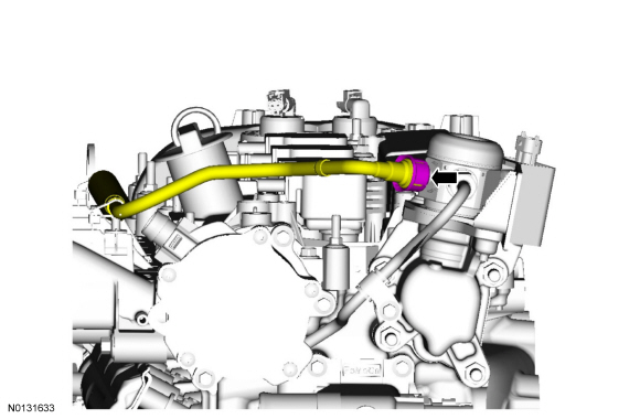
- NOTE: Make sure that a new high pressure fuel tube is installed.
- Hand tighten the high pressure fuel tube-to-fuel rail flare nut.
- Hand tighten the high pressure fuel tube-to-fuel injection pump flare nut.
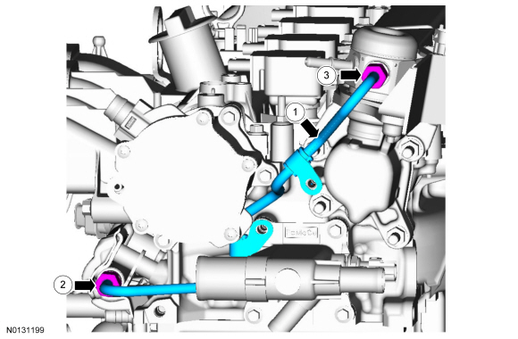
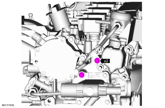
- Loosely install the 2 high pressure fuel tube bracket bolts.
- Tighten the 2 high pressure fuel tube flare nuts in the following 2
stages.
NOTE: Calculate the correct torque wrench setting for the following torque. Refer to the Torque Wrench Adapter Formulas in the Appendix.
- Stage 1: Using a torque adapter, tighten to 15 Nm (133 lb-in).
- Stage 2: Tighten an additional 30 degrees.
- Tighten to 10 Nm (89 lb-in).

- For more information, refer to Section 310-00.

- NOTE: Use care when installing the fuel injection pump noise insulator. Spreading the openings will aid in installing the fuel injection pump noise insulator and reduce the risk of damage.

- Connect the battery ground cable. For additional information, refer to Section 414-01.
- Pressurize the fuel system, For additional information, refer to Section 310-00.
- Install the ACL outlet pipe, for additional information, refer to Section 303-12.
Fuel Pump Control Module
Removal and Installation
NOTE: Removal steps in this procedure may contain installation details.
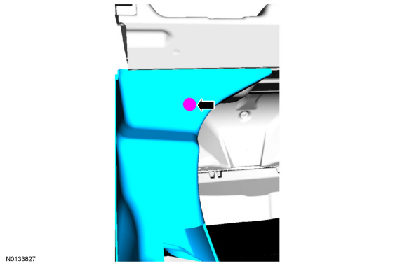
- Fold the RR seat backrest down.
- NOTICE: Do not overtighten the fasteners or damage to the
module will occur.
Tighten to 5 Nm (44 lb-in).
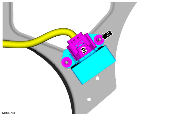
- To install, reverse the removal procedure.
Throttle Body
Removal and Installation
NOTE: Removal steps in this procedure may contain installation details.
- With the vehicle in NEUTRAL, position it on a hoist. For additional information, refer to Section 100-02.
- Remove the intermediate Charge Air Cooler (CAC) outlet tube and the upperCharge Air Cooler (CAC) outlet tube. For additional information, refer to Section 303-12.
- Tighten to 10 Nm (89 lb-in) in the sequence shown.
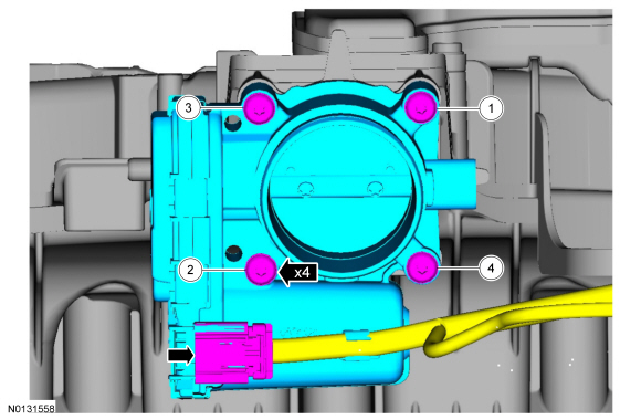
- Discard the specified component. Follow local disposal regulations.
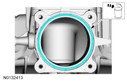
- NOTE: Make sure that a new TB gasket is installed.
To install, reverse the removal procedure.
 Fuel Charging and Controls - 3.5L GTDI
SPECIFICATIONS
Material
Torque Specifications
a Refer to the procedure in this section.
DESCRIPTION AND OPERATION
Fuel Charging and Controls
3.5L Gasoline Turbocharged Direct Injection (GTDI)
W ...
 Fuel Charging and Controls - Turbocharger, 3.5L GTDI
SPECIFICATIONS
Material
Torque Specifications
a Refer to the procedure in this section.
DESCRIPTION AND OPERATION
Turbocharger
NOTICE: Whenever turbocharger air intake system components ar ...
Other materials:
Rear Drive Halfshafts
SPECIFICATIONS
Torque Specifications
a Refer to the procedure in this section.
DESCRIPTION AND OPERATION
Rear Drive Halfshafts
The halfshafts consist of the following components:
Inner CV joints
Outer CV joints
Interconnecting shafts
The halfshafts are splined on the outboard stub s ...
Transmission fluid check
6F35 TRANSMISSION (if equipped)
Note: Transmission fluid should be checked by an authorized dealer.
If required, fluid should be added by an authorized dealer.
The automatic transmission does not have a transmission fluid dipstick.
Refer to your scheduled maintenance information for schedu ...
Description and Operation
Instrument Panel Cluster (IPC)
Overview
Base IPC
Tachometer
Main menu navigation
Main menu text display
LH turn indicator
TPMS warning indicator
MIL
Stability-traction control indicator (sliding car icon)
Stability-traction control disabled indicator (sliding car OFF icon)
Air b ...
