SPECIFICATIONS
Torque Specifications
a Refer to the procedure in this section.
DESCRIPTION AND OPERATION
Rear Drive Halfshafts
The halfshafts consist of the following components:
- Inner CV joints
- Outer CV joints
- Interconnecting shafts
The halfshafts are splined on the outboard stub shaft to drive the wheel hubs. They are retained in the wheel hubs by special wheel hub nuts which also control the wheel bearing preload. The halfshafts are splined on the inboard stub shaft and are retained by circlips. New circlips must be installed whenever the old circlips are removed.
Halfshaft Joint
CV joints consist of the following components:
- CV joint boot clamps
- Convoluted CV joint boots
- Tripod joint housings
- Ball and cage housings
- Retainer circlips
- Special CV high-temperature grease
The CV joints mate the interconnecting shaft with the stub shaft. The joints allow for smooth rotation of the interconnecting shaft and the stub shafts. They also adjust for length variances and angle requirements as the vehicle goes through jounce and rebound.
The halfshaft joints are not repairable and are serviced as assemblies only.
Halfshaft Handling
Handle all halfshaft components carefully during removal and installation and during various component disassembly and assembly procedures.
- Never pick up or hold the halfshaft only by the inboard or outboard CV joint.
- Do not overangle the CV joints.
- Damage will occur to an assembled inboard CV joint if it is overplunged outward from the joint housing.
- Never use a hammer to remove or install the halfshafts from the rear hub.
- Never use the halfshaft assembly as a lever to position other components. Always support the free end of the halfshaft.
- Do not allow the boots to contact sharp edges or hot exhaust components.
- Handle the halfshaft only by the interconnecting shaft to avoid pull-apart and potential damage to the CV joints.
- Excessive pulling force on the interconnecting shaft between joints of the halfshaft will result in internal joint damage. Axial loads used in assisting removal must be applied through the inboard joint housing only.
- Do not drop assembled halfshafts. The impact will cut the boots from the inside without evidence of external damage.
- Do not remove the outer CV joint by pulling on the interconnecting shaft.
- Inspect all machined surfaces and splines for damage.
REMOVAL AND INSTALLATION
Halfshaft
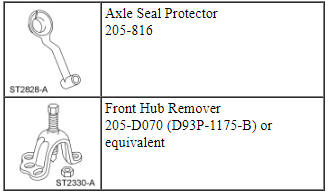
Special Tool(s)
Removal
NOTICE: Suspension fasteners are critical parts because they affect performance of vital components and systems and their failure may result in major service expense. New parts must be installed with the same part numbers or equivalent part, if replacement is necessary. Do not use a replacement part of lesser quality or substitute design. Torque values must be used as specified during reassembly to make sure of correct retention of these parts.
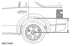
- Measure the distance from the center of the wheel hub to the lip of the fender with the vehicle in a level, static ground position (curb height).
- Remove the wheel and tire. For additional information, refer to Section 204-04.
- Remove the wheel hub nut.
- Do not discard at this time.
- NOTICE: Do not allow the caliper to hang from the brake hose
or damage to the hose can occur.
Remove and discard the 2 brake caliper anchor plate bolts and position the brake caliper and anchor plate assembly aside.
- Support the brake caliper and anchor plate assembly using mechanic's wire.
- NOTE: Use the hex-holding feature to prevent the stabilizer bar
link stud from turning while removing or installing the nut.
Remove and discard the stabilizer bar link upper nut and disconnect the link.
- Remove and discard the toe link-to-wheel knuckle nut and disconnect the link.
- Remove the wheel speed sensor bolt.
- Disconnect the wheel speed sensor harness retainers and position the sensor and harness aside.
- Position a screw-type jackstand under the lower arm.
- Remove and discard the upper arm-to-wheel knuckle nut and bolt and disconnect the knuckle from the upper arm.
- Remove and discard the shock absorber lower bolt and disconnect the shock absorber from the knuckle bracket.
- Loosen, but do not remove the lower arm-to-wheel knuckle bolt.
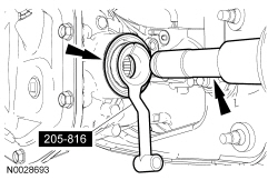
- Using the Front Hub Remover, separate the halfshaft outer CV joint from the hub bearing.
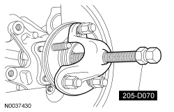
- Swing the wheel knuckle outward and remove the halfshaft outer CV joint from the hub bearing.
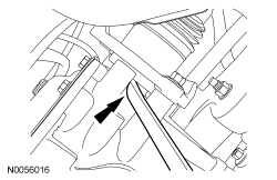
- NOTICE: Do not damage the oil seal when removing the axle
halfshaft from the differential.
Using a suitable pry bar, remove the halfshaft inner CV joint from the differential.
- Remove the halfshaft from the vehicle.
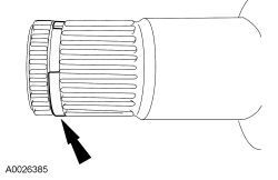
- Remove and discard the circlip from the halfshaft.
Installation
NOTE: Before tightening suspension bushing fasteners, use a jackstand to raise the rear suspension until the distance between the center of the hub and the lip of the fender is equal to the measurement taken in the removal procedure (curb height).
- NOTICE: The circlips are unique in size and shape for each
shaft. Make sure to use the specified circlip for the application or vehicle
damage may occur.
Install a new circlip on the halfshaft.
- Using the Axle Seal Protector, install the halfshaft inner CV joint into
the differential.
- Make sure the circlip locks in the side gear.
- Swing the wheel knuckle inward and install the halfshaft outer CV joint through the hub bearing.
- Position the wheel knuckle to the upper arm and loosely install a new nut and bolt.
- Position the shock absorber and loosely install a new bolt.
- Position the wheel speed sensor harness in the retainers and install the
sensor and bolt.
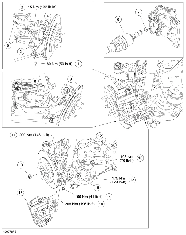
- Tighten to 15 Nm (133 lb-in).
- Position the toe link and loosely install a new toe link-to-wheel knuckle nut.
- Position a suitable jackstand under the lower control arm at the shock and spring assembly attachment point and raise the rear suspension until the distance between the center of the hub and the lip of the fender is equal to the measurement taken in Step 1 of the procedure (curb height).
- NOTE: A slotted upper arm allows for the rear suspension camber
to be adjusted by pushing inward or pulling outward on the wheel knuckle
while tightening the upper arm-to-wheel knuckle nut.
With the wheel knuckle pushed inward for maximum negative camber, tighten the upper arm-to-wheel knuckle nut to 200 Nm (148 lb-ft).
- Tighten the lower arm-to-wheel knuckle bolt to 265 Nm (196 lb-ft).
- Tighten the shock absorber lower bolt to 175 Nm (129 lb-ft).
- Tighten the toe link-to-wheel knuckle nut to 80 Nm (59 lb-ft).
- NOTE: Use the hex-holding feature to prevent the stabilizer bar
link stud from turning while removing or installing the nut.
Connect the stabilizer bar link and install a new stabilizer bar link upper nut.
- Tighten to 55 Nm (41 lb-ft).
- Position the brake caliper and anchor plate assembly and install the 2
bolts.
- Tighten to 103 Nm (76 lb-ft).
- NOTICE: Do not tighten the wheel hub nut with the vehicle on
the ground. The nut must be tightened to specification before the vehicle is
lowered onto the wheels. Wheel bearing damage will occur if the wheel
bearing is loaded with the weight of the vehicle applied.
NOTE: Apply the brake to keep the halfshaft from rotating.
Use the previously removed hub nut to seat the halfshaft.- Tighten to 350 Nm (258 lb-ft).
- Remove and discard the hub nut.
- NOTICE: The wheel hub nut contains a one-time locking chemical
that is activated by the heat created when it is tightened. Install and
tighten the new wheel hub nut to specification within 5 minutes of starting
it on the threads. Always install a new wheel hub nut after loosening or
when not tightened within the specified time or damage to the components can
occur.
NOTE: Apply the brake to keep the halfshaft from rotating.
Install a new hub nut.- Tighten to 350 Nm (258 lb-ft).
- Install the wheel and tire. For additional information, refer to Section 204-04.
- Check and if necessary, adjust the rear toe. For additional information, refer to Section 204-00.
 Front Drive Halfshafts
SPECIFICATIONS
Torque Specifications
a Refer to the procedure in this section.
DESCRIPTION AND OPERATION
Front Drive Halfshafts
The halfshafts consist of the following components:
Inner C ...
 Brake System
...
Other materials:
General operating tips
Manual Climate Control
• To reduce fog build-up on the windshield during humid weather, select
Defrost. You can also improve clearing by increasing the temperature
and fan speed.
• To reduce humidity build-up inside the vehicle, do not drive with the
system off or with recirculated air en ...
Jacking and Lifting
WARNING: When jacking or lifting the vehicle, block all wheels remaining
on the ground. Set the parking brake if the rear wheels will remain on the
ground. These actions help prevent unintended vehicle movement. Failure to
follow these instructions may result in serious personal injury.
&nb ...
Using snow chains
Your Taurus SHO may be equipped with summer tires to provide
superior performance on wet and dry roads. Summer tires do not have
the Mud and Snow (M+S or M/S) tire traction rating on the tire side
wall. Since summer tires do not have the same traction performance as
All-season or Snow tires, For ...
