SPECIFICATIONS
Material
Torque Specifications
a Refer to the procedure in this section.
DESCRIPTION AND OPERATION
Turbocharger
NOTICE: Whenever turbocharger air intake system components are removed, always cover open ports to protect from debris. It is important that no foreign material enter the system. The turbocharger compressor vanes are susceptible to damage from even small particles. All components should be inspected and cleaned, if necessary, prior to installation or reassembly.
The turbocharger assembly consists of the following components:
- LH turbocharger
- RH turbocharger
The turbocharger is an exhaust-driven centrifugal air compressor. Its purpose is to increase power output by supplying compressed air to the engine. The internal components are oil, coolant and air cooled. Engine oil and coolant are circulated through the center housing which acts as a heat barrier between the "hot" turbine and the "cold" compressor. Bearings are sleeve type and lubricated by engine oil. Oil is circulated to the turbocharger center housing and returned to the sump through an oil drain in the center housing.
Expanding exhaust gases drive the turbine shaft assembly to speeds up to 200,000 rpm. Filtered air entering the compressor side of the turbocharger is compressed and delivered through a Charge Air Cooler (CAC). The very hot compressed air is cooled, then continues on to fill the intake manifold at a higher pressure than atmospheric pressure. Because considerably more air is forced into the intake manifold, the results are increased power, fuel efficiency and the ability to maintain power at higher altitudes.
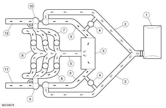
The EcoBoost twin turbochargers are used in a parallel arrangement with one turbocharger connected to each cylinder bank. This configuration improves engine responsiveness due to the reduced interia of 2 small turbochargers. This also leads to an improved turbocharger package and better utilization of heat energy from the compact exhaust manifolds. The compact design of the system allows the catalysts to be located very close to the turbocharger outlet for improved emissions.
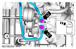
Turbochargers
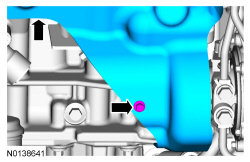
NOTE: Black arrows indicate hot, white arrows indicate cold.
DIAGNOSIS AND TESTING
Turbocharger
Principles of Operation
The turbocharger is an exhaust-driven centrifugal air compressor. Its purpose is to increase power output by supplying compressed air to the engine. The internal components are oil, coolant and air cooled. Engine oil and coolant are circulated through the center housing which acts as a heat barrier between the "hot" turbine and the "cold" compressor. Bearings are sleeve type and lubricated by engine oil. Oil is circulated to the turbocharger center housing and returned to the sump through an oil drain in the center housing.
Expanding exhaust gases drive the turbine shaft assembly to speeds up to 200,000 rpm. Filtered air entering the compressor side of the turbocharger is compressed and delivered through a Charge Air Cooler (CAC). The very hot compressed air is cooled, then continues on to fill the intake manifold at a higher pressure than atmospheric pressure. Because considerably more air is forced into the intake manifold, the results are increased power, fuel efficiency and the ability to maintain power at higher altitudes.
Inspection and Verification
NOTE: This section provides mechanical diagnosis of the turbocharger assembly. If there is a Malfunction Indicator Lamp (MIL) illuminated, or DTCs are present, these should be diagnosed prior to performing turbocharger mechanical diagnosis. Refer to the Powertrain Control/Emissions Diagnosis (PC/ED) manual.
- Verify the customer concern.
- Inspect the entire turbocharger system for obvious signs of damage or
other mechanical concerns, using the following chart.
Visual Inspection Chart
Mechanical
- Oil inlet pipe and connection
- Oil outlet pipe and connection
- Compressor housing inlet circuit and piping
- Compressor housing outlet circuit and piping
- Turbine housing inlet circuit and piping
- Turbine housing outlet circuit and piping
- Turbocharger actuator tubing or linkage
- If the concern(s) remains after the inspection, GO to Symptom Chart.
- If a driveability condition still exists, refer to the Powertrain Control/Emissions Diagnosis (PC/ED) manual.
Symptom Chart
Component Tests
Turbocharger Internal Oil Leak Test
NOTE: Some engine oil may be present in the turbocharger compressor inlet and in the air inlet components due to the crankcase breather system.
Check the turbocharger compressor inlet for evidence of oil. If excessive oil is present, this indicates that the failure could be in the engine or turbocharger. Refer to Section 303-00 or the following turbocharger check. If excessive oil is found in the turbocharger compressor outlet, check the Charge Air Cooler (CAC) for oil contamination. If contamination is present, flush the CAC. Refer to Section 303-12.
Check the turbocharger turbine outlet for evidence of oil. If excess oil is present in the outlet, remove the turbocharger from the engine and examine the oil supply and return passages in the turbocharger and engine block for restriction. If no restriction is found, install a new turbocharger.
Check for Free Rotation - Off Vehicle
NOTE: The turbocharger must be pre-oiled before carrying out this check.
NOTE: Turbine and compressor wheels must spin freely when turned by hand. No housing contact is permitted.
Inspect the turbocharger compressor and turbine fins for damage. If the compressor or turbine wheel fins are damaged, replace the turbocharger.
Press and rotate the turbocharger shaft, then repeat from the opposite side. If either the compressor wheel or the turbine wheel contacts the housing, the bearings are bad and a new turbocharger must be installed.
REMOVAL AND INSTALLATION
Turbocharger - LH
Material
Removal
NOTICE: Whenever turbocharger air intake system components are removed, always cover open ports to protect from debris. It is important that no foreign material enter the system. The turbocharger compressor vanes are susceptible to damage from even small particles. All components should be inspected and cleaned, if necessary, prior to installation or reassembly.
- With the vehicle in NEUTRAL, position it on a hoist. Refer to Section 100-02.
- Remove the Air Cleaner (ACL) assembly. Refer to Section 303-12.
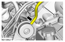
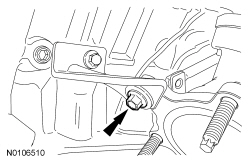
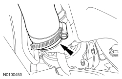
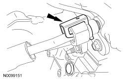
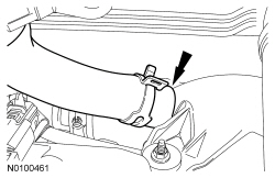
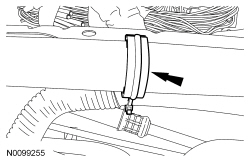
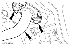
- Disconnect the wastegate control valve hose from the LH turbocharger assembly.
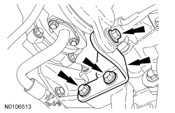
- Remove the 2 bolts from the top of the LH exhaust manifold heat shield.

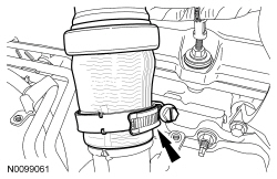
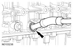
- Loosen the clamp and remove the LH turbocharger intake tube from the turbocharger.

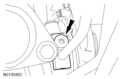
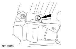
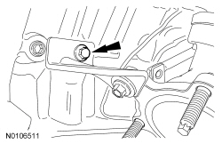
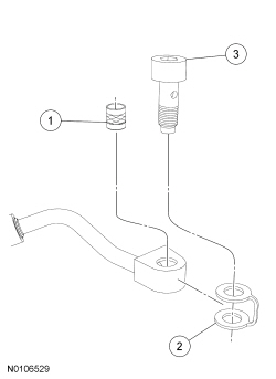
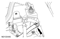
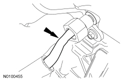
- Remove the LH turbocharger oil supply tube bolt and sealing washer.
- Discard the sealing washer and oil supply tube filter.
- Drain the cooling system. Refer to Section 303-03.
- Remove the LH catalytic converter. Refer to Section 309-00.
- Remove the bottom bolt and the LH exhaust manifold heat shield.

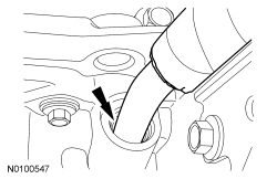
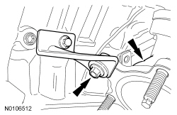
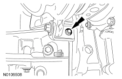
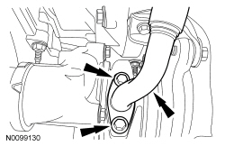
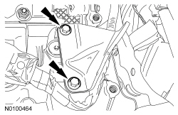
- Remove the 2 LH oil return tube-to-turbocharger bolts.
- Remove and discard the gasket.

- Remove the LH turbocharger oil return tube from the oil pan.
- Discard the 2 O-ring seals.
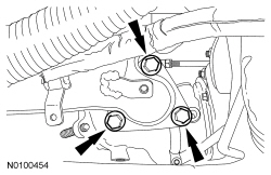
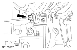
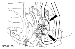
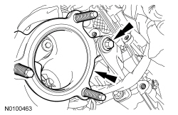
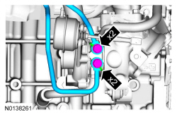
- Remove the 2 coolant tube banjo bolts and the LH turbocharger coolant
tubes.
- Discard the sealing washers.

- Loosen the clamp and remove the LH CAC tube from the LH turbocharger.

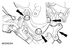
- Remove the 3 exhaust manifold-to-LH turbocharger bolts.
- Discard the gasket and bolts.

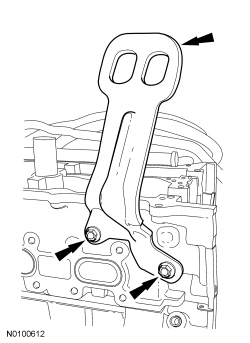
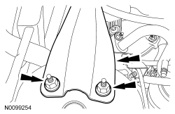
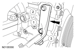
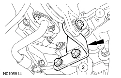
- Remove the 2 bolts and the lower LH turbocharger-to-cylinder block bracket.
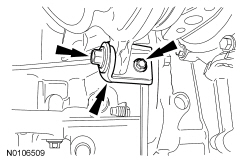
- Remove the upper LH turbocharger bracket-to-turbocharger bolt and the turbocharger assembly.

Installation
- NOTICE: The upper LH turbocharger bracket bolt must be
loosened in order to perform the tightening sequence or damage to the
turbocharger may occur.
Loosen the upper LH turbocharger bracket bolt.
- Install a new LH exhaust manifold-to-turbocharger gasket.
- Install the turbocharger assembly and install upper LH turbocharger
bracket-to-turbocharger bolt.
- Do not tighten the bolts at this time.
- Install the lower LH turbocharger-to-cylinder block bracket and the 2
bolts.
- Do not tighten the bolts at this time.

- Install the 3 new LH exhaust manifold-to-turbocharger bolts.
- Tighten to 45 Nm (33 lb-ft).
NOTICE: The next 4 steps must be performed in the order written or damage to the turbocharger may occur.
- Tighten the upper LH turbocharger bracket-to-turbocharger bolt.
- Tighten to 19 Nm (168 lb-in).
- Tighten the upper LH turbocharger bracket-to-cylinder block bolt.
- Tighten to 25 Nm (18 lb-ft).
- Tighten the lower LH turbocharger bracket-to-turbocharger bolt.
- Tighten to 19 Nm (168 lb-in).
- Tighten the lower LH turbocharger bracket-to-cylinder block bolt.
- Tighten to 11 Nm (97 lb-in).
- NOTE: Align the index marks for the LH CAC tube.
Install the LH CAC tube on the LH turbocharger and tighten the clamp.
- Tighten to 5 Nm (44 lb-in).
- Using 2 new sealing washers, install the 2 coolant tube banjo bolts.
- Tighten to 40 Nm (30 lb-ft).
- NOTE: Lubricate the oil pan bore with clean engine oil.
Using 2 new O-ring seals, install the LH turbocharger oil return tube to the oil pan.

- Using a new gasket, install the LH turbocharger oil return tube and the
2 bolts.
- Tighten to 10 Nm (89 lb-in).
- NOTE: Align the marks for the LH turbocharger intake tube.
Install LH turbocharger intake tube and tighten the clamp.
- Tighten to 5 Nm (44 lb-in).
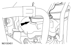
- Install the oil supply tube filter, washer and bolt.
- Install the new oil supply tube filter in the oil supply tube block.
- Slide the new washer onto the oil supply tube block.
- Install the bolt into the oil supply tube block.
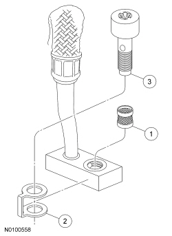
- Install the LH turbocharger oil supply tube.
- Tighten to 40 Nm (30 lb-ft).

- NOTE: Make sure the turbocharger wastegate regulating valve hose
does not contact the exhaust manifold heat shield.
Connect the wastegate control valve hose to the LH turbocharger assembly.

- Install the LH exhaust manifold heat shield and the bottom bolt.
- Do not tighten the bolts at this time.
- Install the 2 top LH exhaust manifold heat shield bolts.
- Tighten to 12 Nm (106 lb-in).
- Tighten the LH exhaust manifold heat shield bottom bolt.
- Tighten to 12 Nm (106 lb-in).
- Install the LH catalytic converter. Refer to Section 309-00.
- Fill and bleed the cooling system. Refer to Section 303-03.
- Install the ACL assembly. Refer to Section 303-12.
Turbocharger - RH
Special Tool(s)
Material
Removal
NOTICE: Whenever turbocharger air intake system components are removed, always cover open ports to protect from debris. It is important that no foreign material enter the system. The turbocharger compressor vanes are susceptible to damage from even small particles. All components should be inspected and cleaned, if necessary, prior to installation or reassembly.
- With the vehicle in NEUTRAL, position it on a hoist. Refer to Section 100-02.
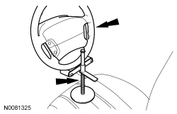
- NOTE: Use a steering wheel holding device (such as Hunter
28-75-1 or equivalent).
Using a suitable holding device, hold the steering wheel in the straight-ahead position.
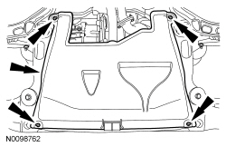
- Remove the 4 retainers and the underbody shield.
- Drain the cooling system. Refer to Section 303-03.
- Remove the RH catalytic converter. Refer to Section 309-00.
- Remove the front subframe. Refer to Section 502-00.
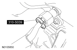
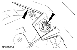
- Remove the RH turbocharger oil supply tube secondary latch.
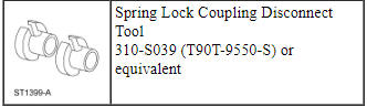
- Using a Spring Lock Coupling Disconnect Tool, remove the RH turbocharger
oil supply tube from the quick connect fitting.
- Inspect and if necessary, replace the quick connect fitting.
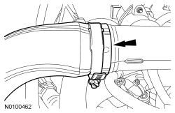
- Loosen the clamp and remove the RH turbocharger intake pipe from the RH turbocharger.
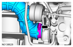
- Disconnect the turbocharger wastegate regulating valve hose from the RH turbocharger assembly.
- Remove the 3 bolts and the RH turbocharger lower bracket.
- Remove the 2 bolts and the RH turbocharger oil return tube from the
turbocharger.
- Remove and discard the gasket.

- Remove the RH turbocharger oil return tube from the cylinder block.
- Discard the 2 O-ring seals.

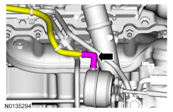
- Remove the 2 coolant tube banjo bolts and the RH turbocharger coolant
tubes.
- Discard the sealing washers. Discard the specified component. Follow local disposal regulations.
- Detach the 2 vacuum hose retainers from the strut tower brace.

- Remove the 4 nuts and the strut tower brace.

- Disconnect the LH turbocharger bypass valve electrical connector and the turbocharger bypass valve hose.
- Remove the turbocharger wastegate regulating valve hose from the RH Charge Air Cooler (CAC) tube.

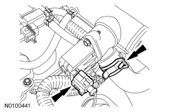
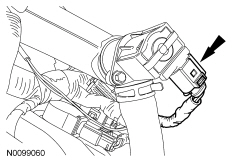
- Disconnect the RH turbocharger bypass valve electrical connector.

- Disconnect the RH turbocharger bypass valve hose.

- Remove the RH CAC tube nut from the intake manifold.

- Loosen the clamp and remove the RH CAC tube.

- Loosen the clamp and remove the RH CAC tube from the RH turbocharger.
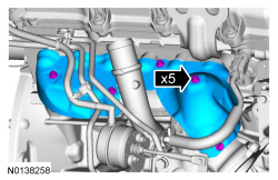
- Remove the 5 bolts and the 2 upper RH exhaust manifold heat shields.

- Remove the 2 bolts and the RH engine lifting eye.

- Remove the 3 RH exhaust manifold-to-turbocharger bolts.
- Discard the gasket.
- Remove the upper RH turbocharger-to-cylinder block bracket bolt and the RH turbocharger assembly.

- Remove the RH turbocharger oil supply tube banjo bolt.
- Discard the sealing washer and oil supply tube filter.
Installation
- Install the oil supply tube filter, washer and bolt.
- Install the new oil supply tube filter in the oil supply tube block.
- Slide the new washer onto the oil supply tube block.
- Install the bolt into the oil supply tube block.
- Install the RH turbocharger oil supply tube.
- Tighten the bolt to 40 Nm (30 lb-ft).
- NOTICE: The upper RH turbocharger bracket bolts must be
loosened in order to perform the tightening sequence or damage to the
turbocharger may occur.
Loosen the 2 bolts for the upper RH turbocharger-to-cylinder block bracket.
- Install a new RH exhaust manifold-to-turbocharger gasket.
- Install the RH turbocharger assembly and the upper RH
turbocharger-to-cylinder block bracket bolt.
- Do not tighten the bolts at this time.
- Install the 3 new RH exhaust manifold-to-turbocharger bolts.
- Tighten to 45 Nm (33 lb-ft).

- Install the RH engine lifting eye and the 2 bolts.
- Tighten to 24 Nm (18 lb-ft).
- Install the 2 upper RH exhaust manifold heat shields and the 5 bolts.
- Tighten to 12 Nm (106 lb-in).
- NOTE: Align the index marks for the RH CAC tube.
Install the RH CAC tube to the RH turbocharger and tighten the clamp.
- Tighten to 5 Nm (44 lb-in).

- NOTE: Align the index marks for the RH CAC tube.
Install the RH CAC and tighten the clamp.
- Tighten to 5 Nm (44 lb-in).
- Install the RH CAC tube and the RH CAC tube nut to the intake manifold.
- Tighten to 6 Nm (53 lb-in).
- Connect the RH turbocharger bypass valve hose.
- Connect the RH turbocharger bypass valve electrical connector.
- Install the turbocharger wastegate regulating valve hose to the RH CAC tube.
- Connect the LH turbocharger bypass valve electrical connector and the turbocharger bypass valve hose.

- Install the strut tower brace and the 4 nuts.
- Tighten to 30 Nm (22 lb-ft).
- Attach the 2 brake booster vacuum hose retainers to the strut tower brace.
- Position the upper RH turbocharger-to-cylinder block bracket as far
clockwise as possible and tighten the bolts in the following sequence.
- Tighten the lower cylinder block bracket bolt to 26 Nm (19 lb-ft).
- Tighten the upper cylinder block bracket bolt to 26 Nm (19 lb-ft).
- Tighten the cylinder block bracket-to-turbocharger bolt to 19 Nm (168 lb-in).
- Using 2 new sealing washers, install the 2 RH turbocharger coolant tube
banjo bolts.
- Tighten to 40 Nm (30 lb-ft).
- NOTE: Lubricate the cylinder block bore with clean engine oil.
Using 2 new O-ring seals, install the RH turbocharger oil return tube in the cylinder block.
- Install a new gasket and install the RH turbocharger oil return tube and
the 2 bolts.
- Tighten to 10 Nm (89 lb-in).
- Install the lower RH turbocharger bracket and the 3 bolts and tighten in
sequence shown.
- Tighten the lower RH turbocharger bracket-to-turbocharger bolt to 19 Nm (168 lb-in).
- Tighten the 2 lower RH turbocharger bracket-to-cylinder block bolts to 48 Nm (35 lb-in).
- NOTE: Make sure the turbocharger wastegate regulating valve hose
does not contact the exhaust manifold heat shield.
Connect the turbocharger wastegate regulating valve hose to the RH turbocharger.

- NOTE: Align the index marks for the RH turbocharger intake pipe.
Install the RH turbocharger intake pipe to the RH turbocharger and tighten the clamp.
- Tighten to 5 Nm (44 lb-in).

- NOTE: Listen for audible click when installing the oil supply
tube into the quick connect fitting.
Install the RH turbocharger oil supply tube into the quick connect fitting.
- Install the RH turbocharger oil supply tube secondary latch.

- Install the front subframe.
- Install the RH catalytic converter.
- Fill and bleed the cooling system.
- Install the underbody shield and the 4 retainers.

 Fuel Charging and Controls - 2.0L GTDI
SPECIFICATIONS
Material
Torque Specifications
a Refer to the procedure in this section.
DESCRIPTION AND OPERATION
Fuel Charging and Controls
Component Locations
WARNING: Do
not smoke, carry li ...
 Fuel Charging and Controls - Turbocharger, 2.0L GTDI
SPECIFICATIONS
Torque Specifications
a Refer to the procedure in this section.
DESCRIPTION AND OPERATION
Turbocharger
Component Location
Overview
NOTICE: Whenever turbocharger air intake ...
Other materials:
Assembly
Engine
Special Tool(s)
Material
Engine Upper
Engine Front
Engine Upper - LH Cylinder Head
Engine Upper - RH Cylinder Head
Timing Drive Components
Lower Engine Block (View 1)
Lower Engine Block (View 2)
NOTICE: During engine repair procedures, cleanliness is extremely
i ...
Disassembly and Assembly of Subassemblies
Transaxle Case
Special Tool(s)
Exploded View
Disassembly
Special Tool(s): Remover/Installer, Front Wheel Hub 204-069
(T81P-1104-C), Transfer Gear Bearing Race Remover 307-577
Punch a hole in the fluid dam. Center punch.
General Equipment: Dent Puller
Special Tool(s): Dif ...
Specifications, Description and Operation
SPECIFICATIONS
Material
General Specifications
Torque Specifications
DESCRIPTION AND OPERATION
Wipers and Washers
Overview
The windshield wiper/washer system is activated by the wiper/washer controls
on the multifunction switch. The following functions/features of the windshield
wiper/washer sy ...
