Instrument Panel Cluster (IPC)
Overview
Base IPC
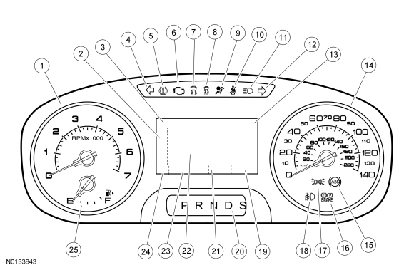
- Tachometer
- Main menu navigation
- Main menu text display
- LH turn indicator
- TPMS warning indicator
- MIL
- Stability-traction control indicator (sliding car icon)
- Stability-traction control disabled indicator (sliding car OFF icon)
- Air bag warning indicator
- Safety belt warning indicator
- High beam indicator
- RH turn indicator
- Cruise control display area
- Speedometer
- ABS warning indicator
- Brake warning indicator
- Lights on indicator
- Fog lamp indicator
- Odometer
- PRNDL display
- Compass display
- Message center display area
- Message center indicator display area
- Select shift display area
- Fuel gauge
Optional IPC
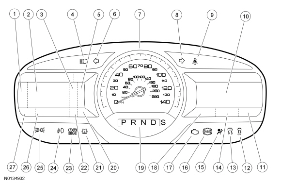
- Menu navigation icon
- LH message center display (also displays the analog style tachometer and select shift display [if equipped] and AWD gauge [if equipped] )
- Adaptive cruise control display (if equipped)
- High beam indicator
- Fuel gauge, fuel gauge/tachometer or fuel gauge/temperature gauge display
- LH turn indicator
- Speedometer
- RH turn indicator
- Safety belt warning indicator
- RH multimedia display area
- Clock display
- Stability-traction control disabled indicator (sliding car OFF icon)
- Stability-traction control indicator (sliding car icon)
- Compass display
- Air bag warning indicator
- ABS warning indicator
- MIL
- Outside air temperature
- PRNDL display
- Select shift display area
- TPMS warning indicator
- Cruise control message center indicator (fixed)
- Brake warning indicator
- Fog lamp indicator
- Lights on indicator
- Message center indicator display area (rotating)
- Odometer
The base IPC is available with a single LCD screen. The optional IPC is available with dual RH and LH LCD screens. The single display screen and the LH display screen contain the message center information. The RH display screen displays multimedia information (audio, phone and navigation), as well as items such as vehicle direction, outside air temperature and time.
Refer to the appropriate section in Group 415 for the procedure.
Informational Indicators/Warning Indicators
Informational indicators provide information to the driver of conditions that exist in the vehicle. Warning indicators provide information to the driver of conditions that could potentially cause personal injury or alter vehicle performance.
Message Center Indicators
Message center indicators illuminate in the message center and replace the typical informational or warning indicator using the same iconic representation. When multiple warnings exist, the message center indicators cycle through each display until the condition has been corrected unless the message center indicator is in a fixed position. The message center indicators include:
- Charging system
- Cruise control (fixed location)
- Door/luggage compartment lid ajar
- Engine oil pressure
- Engine over-temperature
- Grade assist
- Low fuel
- Low washer fluid
- Powertrain malfunction (wrench)
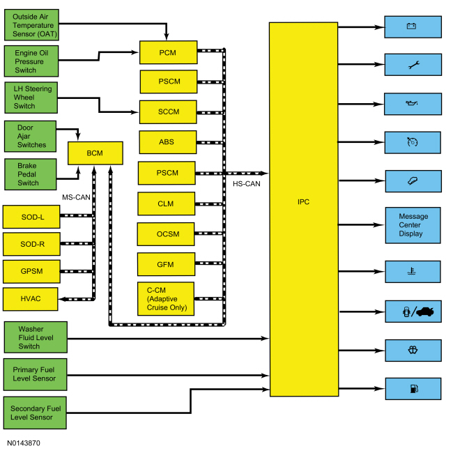
Networked Message Inputs
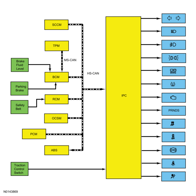
Module messaging has increased over time and has become the standard for sending and receiving information required to operate the IPC. The majority of the inputs required to operate the IPC are received over the CAN.
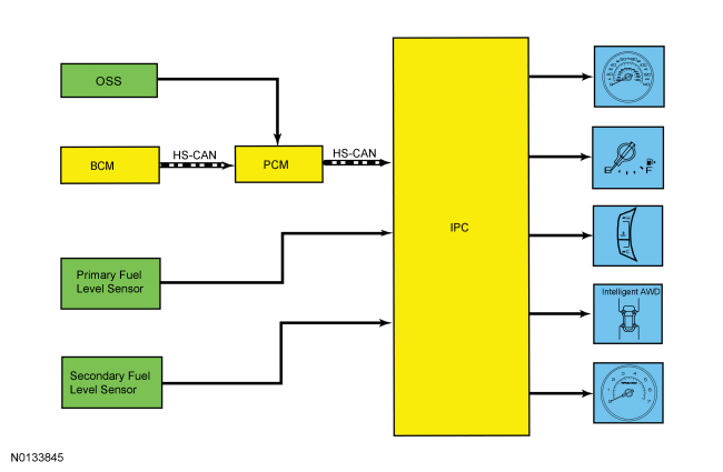
Hardwired Inputs
The IPC requires hardwired inputs from components that are not on either the HS-CAN or the MS-CAN. These components are required for specific IPC functions or gateway requirements. For additional information about the gateway function, Refer to Gateway Function in Section 419-10.
The hardwired inputs are provided by:
- Fuel pump assembly (primary fuel level input)
- Fuel level sensor (secondary fuel level input)
- Park detect switch (part of the floor shifter assembly)
- Washer fluid level switch
System Operation
Network Message Chart - Gauges
System Diagram - Gauges
Module Network Input Messages - IPC
System Diagram - Indicators
Network Message Chart - Indicators
Module Network Input Messages - IPC
Networked Input Messages and Default States
The IPC uses input messages from other modules to control the gauges, informational indicators, and warning indicators over the communication networks. If a required message is missing or invalid for less than 5 seconds, the gauge or indicator that requires the message remains at the last commanded state based upon the last message received. For example, if the stability-traction control status message is missing for less than 5 seconds and the stability-traction control indicator (sliding car icon) was on, the indicator remains on until the next message is received. If the message remains missing or invalid for more than 5 seconds, the IPC sets a U-code DTC and the IPC output becomes a default action for the indicator or gauge. Each indicator or gauge utilizes a different default strategy depending on the nature of the indication. Refer to the diagnostic overview descriptions located before each individual pinpoint test for further description of the default action specific to each indicator or gauge. If the missing messaged input to the IPC returns at any time, the normal function of the gauge or indicator resumes.
NOTE: Whenever a network message is suspected as missing and confirmed by a missing message DTC (U-code), it is important to look for other symptoms that may also be present in the IPC and throughout the vehicle. Once a DTC sets in the IPC, it may be helpful to review the complete message list. Refer to Section 418-00, CAN Multiplex Messages Description and Operation, to determine which other modules also rely on the same message and run the self-test for those modules. If the message is missing from other modules, the same DTC may also be set in those modules. Confirmation of missing messages common to multiple modules may indicate the originating module is the source of the concern or the communication network may be faulted.
It is very important to understand:
- where the input originates.
- all the information necessary for a feature to operate.
- which module(s) receive(s) the input or command message.
- which module controls the output of the feature.
- whether the module that receives the input controls the output of the feature, or whether it outputs a message over the communication network to another module.
Configuration
The IPC contains items that are configurable. Configurable items include customer preference items, which can also be set with a scan tool. The remaining configurable items can only be set by the PMI procedure by uploading/downloading existing configuration or by using As-Built data. Refer to the scan tool instructions. The configurable IPC items are:
Dealer Test Mode
To enter the IPC dealer mode, begin with the ignition in the OFF mode. Press and hold the LH steering wheel switch OK button. Place the ignition in the ON mode and hold the button until the dealer test mode popup window appears, usually within 3 to 5 seconds. Press the up or down arrow buttons to navigate through each of the display windows. To exit the IPC self-test mode, press and hold the OK button for 3-5 seconds or place the ignition in the OFF mode. The dealer test mode displays multiple items in a viewing window on the LH side of the IPC. Each button press advances the viewing window to the next set of items.
NOTE: The table below lists the displays as they appear when navigating using the down arrow button.
Transport Mode
The vehicle is placed in a transport mode at the completion of production to reduce the drain on the battery. Various systems may be altered in how they operate or are disabled when in the transport mode. The vehicle automatically reverts to normal operation after 201 km (125 miles). To disable or turn off the transport mode, carry out the following within 10 seconds:
- Verify the battery is fully charged.
- With ignition in RUN, press brake pedal 5 times.
- Press hazard switch 4 times (on, off, on, off).
Factory Mode
During vehicle assembly, the vehicle defaults to factory mode. Factory mode sets the function timers such as PRNDL display to further reduce the drain on the battery during assembly. The vehicle is placed into transport mode at the end of vehicle assembly. The vehicle remains in factory mode for 60 ignition cycles or until it is manually changed to transport mode.
Gateway Function
The IPC acts as a gateway module by receiving information in one format and transmitting it to the audio and multimedia modules using another format. This enables network communication between modules that do not communicate using the same network ( I-CAN or HS-CAN ).
MyKey
The MyKey feature allows the customer to program a restricted driving mode that is tied to one or more keys known as a MyKey key. When a MyKey programmed key is in use, the IPC provides the following functions:
- At the beginning of vehicle start up, as part of the welcome strategy, the message center greets the MyKey driver with MYKEY ACTIVE DRIVE SAFELY displayed in the message center. If the MyKey speed limiter feature is turned on, the message center also displays the MyKey administrator selected top speed setting message; SPEED LIMITED TO XXX KM/H (XX MPH). The MyKey top speed selections are; 100, 110, 120 or 130 kmh (60, 70, 75, or 80 mph).
- The IPC continuously provides a periodic Belt-Minder warning chime until the driver and passenger safety belts are buckled. When the Belt-Minder is issued, the ACM is muted and the message center displays BUCKLE UP TO UNMUTE AUDIO.
- If the MyKey speed limiter feature is turned on and the vehicle speed approaches the selected top speed (100, 110, 120 or 130 kmh [60, 70, 75, or 80 mph] ), the message center displays VEHICLE NEAR TOP SPEED along with a chime.
- If the MyKey speed limiter feature is turned on and the vehicle speed reaches the selected top speed (105, 110, 120 or 130 kmh [65, 70, 75, or 80 mph] ), the message center displays TOP SPEED MYKEY SETTING along with a chime.
- If the speed warning is selected at one of the preset values (75, 90, 105 km/h [45, 55, 65 mph] ) and the vehicle approaches the preset speed, the message center displays CHECK SPEED DRIVE SAFELY along with a chime.
- If the traction control always on feature is turned on and the MyKey driver attempts to disable the traction control, the message center displays TRACTION CONTROL ON MYKEY SETTING (base IPC ) or ADVTRAC ON MYKEY SETTING (optional IPC ).
- At approximatley 1/8 tank of remaining fuel, the IPC illuminates the low fuel message center indicator and the message center displays FUEL LEVEL LOW along with a chime.
- MyKey Emergency 911 Assist feature and the Do Not Disturb feature can both be found in the MyKey menu.
- MyKey miles driven by the MyKey user can be found in the information display.
- The number of MyKey programmed and administrator keys can be found in the information display.
- The parking aid, BLIS / CTA and collision avoidance warning menus are disabled in the message center to force these features always on.
When an administrator key is in use, the IPC provides the following functions:
- The message center provides a menu guiding the user to create a MyKey. When the maximum MyKey limit is reached, the MyKey creation menu is no longer available.
- The message center provides menus for setting 6 optional MyKey
features:
- MyKey speed limiter
- MyKey pre-selected speed warning
- MyKey radio volume limiter
- Traction control on/off
- MyKey emergency 911 assist feature
- MyKey do not disturb feature
- The message center provides a menu to clear all MyKey programmed keys at once.
- MyKey mileage driven by the MyKey user can be found in system check function of the message center.
- The number of MyKey programmed keys and administrator keys can be found in the system check function of the message center.
For information on the MyKey features, refer to the Owner's Literature.
MyFleet Management (Optional)
The MyFleet management provides an optional police enhanced speed limiting feature that allows the configuration of the maximum vehicle speed. The police enhanced speed limiting feature must be configured using a diagnostic scan tool and can be configured in increments of 8 km/h (5 mph) beginning at 145 km/h (90 mph) up to 8 km/h (5 mph) less than the vehicle's maximum speed.
Prove-Out
The IPC and other vehicle modules carry out a display prove-out to verify all module controlled warning/indicator lamps and monitored systems are functioning correctly within the IPC. The IPC and other modules, such as the RCM, provide a timed prove out while other indicators illuminate until engine start up. When the ignition is cycled to on with the engine off, the indicators illuminate to prove-out according to the following table:
Startup-Shutdown
The IPC provides a startup/shutdown sequence also known as a welcome/farewell strategy. When the vehicle receives a RKE request or a door ajar (open) message, the IPC illuminates the gauge trim rings and pointers. When the ignition is placed in the ACC mode, all cluster backlighting, gauges and indicators are turned off. When the ignition is placed into the RUN or START mode, the IPC begins a prove-out stage. During the prove-out stage, the IPC illuminates all LED indicators for a predetermined time and provides message center information. For the shutdown, the IPC reverses the startup process.
Transport Mode
During vehicle build, some vehicle modules ( IPC, BCM and RFR module [if equipped] ) are set in factory mode. While in the factory mode the IPC displays FACTORY MODE CONTACT DEALER in the message center. If the vehicle is set in factory mode, the system does not automatically exit the mode and must be manually set to either the transport or normal operation mode. When the vehicle build is complete, the vehicle is set to transport mode. While in transport mode, the IPC displays TRANSPORT MODE CONTACT DEALER in the message center. Transport mode is used to reduce the drain on the battery during longer periods where the vehicle is not used. Various systems may be altered or are disabled when in the transport mode. The vehicle automatically reverts to normal operation mode after being driven 201 km (125 mi). To disable or turn off the transport mode, refer to Section 419-10.
Fuel Gauge
The IPC sends a reference voltage to the fuel level sender(s). As the fuel level changes, a float actuates the variable resistor fuel level sender, raising or lowering the fuel level signal voltage. The IPC monitors the changes in voltage from both senders and commands the fuel gauge with a corresponding movement of the pointer.
After a fuel fill up, the time for the fuel gauge to move from empty (E) to full (F) ranges from 2 seconds to 55 minutes depending on which operating mode the fuel gauge is in.
The IPC uses 4 different operating modes to calculate the fuel level:
- Anti-slosh (default mode)
- Key OFF fueling
- Key ON fueling
- Recovery
After a fuel fill up, the time for the fuel gauge to move from empty (E) to full (F) ranges from 2 seconds to 55 minutes depending on which operating mode the fuel gauge is in.
Anti-Slosh Mode
The default fuel gauge mode is called the anti-slosh mode. To prevent fuel gauge changes from fuel slosh (gauge instability due to changes in fuel sensor readings caused by fuel moving around in the tank), the fuel gauge takes approximately 55 minutes to go from empty (E) to full (F).
Key Off Fueling Mode
The key OFF fueling mode (2 seconds to read empty [E] to full [F] ) requires 3 conditions be met:
- The ignition must be in the OFF mode when refueling the vehicle.
- At least 9% of the vehicle's fuel capacity must be added to the fuel tank.
- The IPC must receive a valid ignition ON fuel sensor reading within one second of the ignition being put into the RUN mode. The key ON sample readings are considered valid if the fuel sensor reading is between 10 ohms +- 2 ohms and 180 ohms +- 4 ohms.
If these conditions are not met, the fuel gauge stays in the anti-slosh mode, which results in a slow to read full (F) event.
Key On Fueling Mode
The key ON fueling mode (approximately 60 seconds to read empty [E] to full [F] ) requires the following conditions be met:
- The transmission is in PARK (P) or NEUTRAL (N).
- The ignition is in the RUN mode.
- At least 9% of the vehicle's fuel capacity must be added to the fuel tank.
In key ON fueling mode, a 30-second timer activates after the transmission is put into the PARK (P) or NEUTRAL (N) position. When the 30-second time has elapsed and at least 9% of the vehicle's fuel capacity has been added, the fuel gauge response time is 60 seconds to read from empty (E) to full (F). When the transmission is shifted out of PARK (P) or NEUTRAL (N), the fuel gauge strategy reverts to the anti-slosh mode. The key ON fueling mode prevents slow to read full events from happening if the customer refuels the vehicle with the ignition in the RUN mode.
Recovery Mode
Recovery mode is incorporated into the IPC strategy to recover from a missing fuel level input after a refueling event. Missing fuel level inputs result from intermittent opens in the fuel sensor or its circuits. Recovery mode (empty [E] to full [F] approximately 20 minutes) is initiated when the following 2 conditions are met:
- The IPC is in the anti-slosh (default) mode.
- The actual fuel level in the tank is greater than what is being displayed by the fuel gauge.
Temperature Gauge
The temperature gauge is located in the LCD display area and is a graphical image as opposed to the more traditionally recognized analog gauge. The base IPC uses a thermometer style image that moves upward as the engine temperature increases, changing color as the temperature reaches predetermined ranges. When the temperature is in the cold band, the thermometer color is blue. When the temperature is in the normal band, the thermometer color is gray and when the temperature is in the hot band, the thermometer color is red. The optional IPC uses a more traditional gauge image with a single bar set horizontally across the gauge and moves vertically from bottom to top as the engine temperature increases. The PCM uses the CHT sensor to measure the engine temperature. The IPC uses the engine coolant temperature message from the PCM to control the temperature gauge indication.
Speedometer
The PCM calculates the vehicle speed from the transmission OSS sensor input and from the tire size and axle ratio configuration in the PCM VID block. The PCM provides the IPC with a vehicle speed data message to command the speedometer pointer.
The IPC provides a tolerance which allows the gauge to display between 3% lower and 7% higher than the actual vehicle speed. This means that with an actual vehicle speed of 96.6 kmh (60 mph), the speedometer may indicate between 93.7 kmh (58.2 mph) and 103.3 kmh (64.2 mph), which is normal.
For vehicles with the police package, the tolerance allows the gauge to display between 4.9% lower and 4.9% higher than the actual vehicle speed. This means that with an actual vehicle speed of 96.6 kmh (60 mph), the speedometer may indicate approximately between 93.2 kmh (57.1 mph) and 103.2 kmh (62.9 mph), which is normal.
Odometer
The IPC receives the odometer count message from the PCM. The IPC monitors the odometer count input from the PCM and commands the odometer with a digital display in the message center.
Tachometer
The PCM uses the CKP sensor to measure the engine rpm. The IPC uses the engine Revolutions Per Minute (RPM) data message from the PCM to control the tachometer. The base and optional IPC tachometers appear differently but function the same. The base IPC uses an analog gauge. The optional IPC uses a digital display that provides a 6,000 rpm bar graph or a 7,000 rpm simulated analog gauge display depending on the selected display mode.
AWD Gauge
The AWD gauge displays the level of power applied to each wheel. The IPC uses the following inputs to determine the AWD gauge display:
- wheel torque data
- AWD lock torque
- engine rpm data
- speedometer fault
As power is applied to the wheels, the area directly in front of each displayed wheel begin to fill in. The lowest power displayed is the closest to the wheel. As the amount of power sent to the wheels increases, the area fills in either forward (front wheels) or rearward (rear wheels) of the wheels.
Brake Warning Indicator
The IPC uses 3 basic messaged inputs to control the brake warning indicator. The first 2 messages are the parking brake position switch and the brake fluid level switch sent from the BCM. The third is the for EBD and low brake booster vacuum or vacuum sensor fault messages sent from the ABS module.
The parking brake position switch is hardwired to the BCM through a single signal circuit, while using a separate ground to control the input. The brake fluid level switch is hardwired to the BCM through separate signal and return circuits to control the input.
The BCM provides a reference voltage to both the parking brake position switch and the brake fluid level switch. When the parking brake is applied, the parking brake position switch closes to ground, pulling the reference voltage on the parking brake signal circuit low. When a low brake fluid level condition exists, the brake fluid level switch closes to ground pulling the reference voltage on the brake fluid level signal circuit low. When the brake fluid level switch is disconnected, the reference voltage on the brake fluid level signal circuit is sent high. When the BCM detects the parking brake is applied, a low brake fluid level condition exists or the brake fluid level switch is disconnected, the BCM sends the IPC a brake warning indicator request.
When the ABS module detects a base brake system concern or other ABS related concerns that affect the EBD function or brake booster vacuum, the ABS module sends a brake (red) warning indicator request to the IPC to illuminate the brake warning indicator and the ABS warning indicator.
ABS Warning Indicator
The IPC uses the ABS warning indicator request from the ABS module to control the ABS warning indicator. If a fault condition exists in the ABS, the ABS module sends the IPC the ABS warning indicator request to either flash or illuminate the ABS warning indicator.
Stability-Traction Control Indicator (Sliding Car Icon)
The IPC uses a traction control indicator request message from the ABS module to control the stability-traction control indicator (sliding car icon). The stability-traction control indicator (sliding car icon) flashes when the vehicle stability-traction control is in active mode or is being controlled by the ABS module. The stability-traction control indicator (sliding car icon) illuminates continuously if a fault condition exists in the stability-traction control system. The IPC monitors the traction control indicator request message from the ABS module and either flashes the stability-traction control indicator (sliding car icon) or illuminates it steady depending on the condition.
Stability-Traction Control Disabled Indicator (Sliding Car OFF Icon)
The stability-traction control is configured on/off through the message center. When the stability-traction control is configured on or off, the IPC sends a message to the ABS module indicating the stability-traction control system has been enabled or disabled by the driver. The ABS module either enables or disables the stability-traction control system, and sends a traction control disabled (OFF) indicator request back to the IPC to illuminate or turn off the stability-traction control disabled indicator (sliding car OFF icon) based upon the system state. The stability/traction control system defaults back on or enabled once the ignition is cycled off then back on again.
When a MyKey programmed key is in use and the AdvanceTrac on feature is configured always on, the traction control system cannot be disabled and the stability-traction control disabled indicator (sliding car OFF icon) does not illuminate when the traction control is disabled. The stability-traction control indicator still functions normally to indicate a stability-traction control system fault and a stability-traction control active event.
Safety Belt Warning Indicator
The RCM monitors the safety belt position through the safety belt buckle switch. The RCM sends a safety belt indicator request to the IPC to illuminate the safety belt warning indicator.
Air Bag Warning Indicator
The IPC receives the air bag warning indicator lamp request from the RCM. If a SRS concern is detected, the RCM sets a DTC and sends an air bag indicator lamp request to the IPC to illuminate the air bag warning indicator.
LH-RH Turn Signal Indicator
When the multifunction switch is in the LH or RH turn position or if the hazard switch is on, a turn indicator command message is sent to the IPC from the BCM. Upon receipt of the applicable turn signal on/off request, the IPC flashes the turn signal indicator on and off.
High Beam Indicator
When the high beams are turned on, the BCM sends a headlamp high beam indicator request to the IPC to illuminate the high beam indicator.
TPMS Warning Indicator
The IPC receives the TPMS data from the BCM. The BCM receives the tire pressure status message from the TPM module. If the BCM determines the tire pressure has exceeded the low tire pressure limits, a tire pressure status message is sent to the IPC to illuminate the TPMS warning indicator. If a TPMS fault condition exists, the BCM sends the tire pressure status message to the IPC. The IPC flashes the TPMS warning indicator for 75 seconds, then illuminates the indicator continuously.
When the TPMS is in tire train mode, the BCM sends a message to the IPC to flash the TPMS warning indicator.
Lights On Indicator
When the parking lamps are turned on either through the exterior lighting functions or the illuminated entry feature, the BCM sends the position light indication message to the IPC to illuminate the lights on indicator.
MIL
The MIL is controlled by the IPC using an engine MIL request from the PCM.
PRNDL/Select Shift Indicator
The IPC receives the selector lever (PRNDL) status message from the PCM. The IPC also uses a park detect switch (part of the selector lever) input to signal the IPC that the shift lever is fully seated in the PARK (P) position. The IPC compares the park detect switch input with the selector lever (PRNDL) status message sent from the PCM and illuminates the appropriate gear position in the PRNDL indicator.
The IPC provides a battery reference voltage to the brake shift interlock. When the selector lever is in PARK (P), the brake shift indicator routes the reference voltage to ground, pulling the circuit low to the IPC. When the selector lever is moved out of PARK (P), the brake shift interlock opens the ground sending the reference voltage high.
The select shift display area indicates to the driver which gear is currently selected when the transmission is in the select shift mode. When the transmission is in select shift sport mode, the gear number is displayed in the select shift display area (example: 1, 2, 3 etc).
Component Description
Brake Fluid Level Switch
The brake fluid level switch is a reed-type switch that is mounted through the master cylinder reservoir. The reservoir uses a magnet incorporated into the float. The brake fluid level switch is hardwired to the BCM through separate signal and return circuits and is grounded to a body ground through a separate circuit. The BCM provides a reference voltage to the brake fluid level switch. When the brake fluid level is low, the float drops allowing the magnet to close the reed switch, pulling the reference voltage low. When the brake fluid level is high, the float lifts, releasing the switch contacts and removing the ground to the BCM.
Fuel Level Sender
The fuel level sender is mounted to the fuel pump assembly or the fuel level sensor. The fuel level sender is a dual sweep potentiometer style resistor connected to a float mechanism. The dual sweep design provides a second resistance measurement that reduces the intermittent loss of data due to corrosion between the resistor wires and the sweep arm. As the fuel level changes, the float rises or falls with the fuel level moving the sweep arm across the resistor wires. This movement either increases or decreases the resistance through the unit. The fuel level sensor resistance ranges from 180 ohms +- 4 ohms at empty (E) to 10 ohms +- 2 ohms at full (F). When the fuel level is low, the fuel level sensor resistance is high. When the fuel level is high, the fuel level sensor resistance is low.
Both the fuel pump assembly and fuel level sensor are hardwired to the IPC through separate signal and return circuits. The fuel level return circuits are grounded internally in the IPC. The IPC provides a reference voltage on the fuel level signal circuit. As the fuel level changes, the change in resistance raises or lowers the fuel level signal voltage depending on the resistance of the fuel level sender.
Parking Brake Position Switch
The parking brake position switch is hardwired to the BCM through a signal and return circuit. The BCM provides a reference voltage on the signal circuit. The return circuit is grounded internally in the BCM. When the parking brake is not applied, the parking brake position switch is open. When the parking brake is applied, the parking brake position switch closes, pulling the reference voltage low.
Park Position Detect Switch
The park position detect switch is hardwired to the IPC through a single signal circuit. The park position detect switch is hardwired to a separate ground circuit. The IPC provides a reference voltage to the park position detect switch. When the selector lever is in PARK (P), the park position detect switch routes the reference voltage to ground, pulling the circuit low to the IPC. When the selector lever is moved out of PARK (P), the park position detect switch opens to ground sending the reference voltage high.
IPC
The IPC provides the driver with a system status and alerts the driver when certain conditions exist in the vehicle. The IPC requires PMI when the IPC is replaced.
Information And Message Center
Overview
The message center is an integral part of the IPC that receives and acts upon much of the same information that is input and used to operate the IPC gauges, indicators, and warning indicators. The message center uses both hardwired and the network based inputs to receive information.
The message center functionality is controlled through the message center switch (part of the LH steering wheel switch), which is hardwired to the SCCM through input and return circuits.
Whenever conditions are present that require a warning message, the message center replaces the last selected display with the new warning display. Once the message is reset or cleared, the message center returns to the last selected display. If multiple warnings are present, the message center displays each warning for approximately 4 seconds. Warning messages are also generally associated with other observable outputs of the IPC (gauges, indicators and message center indicators). For example, when the BCM detects a low brake fluid condition, the BCM sends the IPC a request to illuminate the brake warning indicator and a request to display the LOW BRAKE FLUID message in the message center. This allows the message center to be a more informative supplement to the IPC gauges and indicators.
Another function of the message center is to display message center warning indicators. Similar to the interaction between the message center and the standard warning indicators, the message center often displays a warning message and the message center warning indicator simultaneously. For example, if the IPC detects low washer fluid level condition, the IPC illuminates the low washer fluid level message center indicator and displays WASHER FLUID LEVEL LOW in the message center. If multiple warnings are present, requiring multiple message center warning indicator displays, the message center cycles or rotates through the displays in the same manner the message center cycles the text messages.
System Warning Messages
The system warning messages alert the operator to possible problems or malfunctions in the vehicle operating systems. System warning messages may be stand-alone messages but are often associated with another form of indication such as a gauge, an indicator or message center indicator. The message center displays the last selected feature if there are no additional warning messages. Once a warning message has been displayed, the message must be acknowledged to allow full functionality of the message center. Press the OK button to acknowledge and clear the warning message.
When the IPC receives a request to display an informational warning message or a fault condition warning message, the message center may display an informatinal message or a fault condition message. For a complete list of warning messages, refer to the Owner's Literature.
System Operation
System Diagram
Network Message Chart
Module Network Input Messages - IPC
Compass Display - SYNC
The vehicle heading is displayed in the message center as a 1 or 2 character display that indicates the current direction of the vehicle (N, NE, E, SE, S, SW, W, or NW). The compass signal originates with the GPSM. The GPSM sends the GPS compass direction message to the IPC through (gateway) the BCM to the IPC. No calibration or zone adjustment is available, as the compass heading is based on the GPS signal. Refer to the appropriate section in Group 415 for the procedure..
Compass Display - Except SYNC
The vehicle heading is displayed in the message center as a 1 or 2 character display that indicates the current direction of the vehicle (N, NE, E, SE, S, SW, W, or NW). The compass continuously re-calibrates due to changes in the earth's magnetic field and remains accurate during most driving conditions. The compass signal originates with the compass module and is transmitted to the BCM through a LIN line. The BCM in turn sends the compass display data message to the IPC through the CAN.
Keypad Factory Code Display
The message center can display the original keypad factory code when requested. Refer to Section 501-14A or Section 501-14B Description and Operation (D&O) for the procedure to display the keypad factory code.
Oil Change Minder
The message center provides an oil change minder to inform the driver that an oil change is required. The duration of the interval between oil changes is calculated in the PCM and varies due to driving conditions. The PCM assumes a base mileage of 16,090 km (10,000 mi) or 1 year for normal driving. However, this number is adjusted down for conditions such as high engine temperature, high engine rpm, use of flex fuel and possibly low oil level. The PCM calculates and provides the engine oil life percent message to the IPC.
When the remaining oil life is between 1%-5%, the message center displays the change oil soon message. When the remaing oil life is at 0%, the message center displays the oil change required message.
Outside Air Temperature Display
The AAT sensor is hardwired to the PCM through separate input and return circuits. The PCM provides a reference voltage to the AAT sensor and monitors the change in voltage resulting from changes in resistance as determined by outside air temperature. The PCM messages the outside air temperature data to the HVAC module through the BCM. The HVAC module filters the temperature data and sends the updated temperature status back to the BCM. The BCM in turn messages the outside air temperature in degrees Celsius (metric) to the IPC. When the Fahrenheit (English) display is selected by the driver, the IPC converts the Celsius to Fahrenheit and displays the temperature in the message center.
The HVAC module is programmed to update the messaged outside temperature data at different rates depending on several criteria to prevent false temperature displays due to a condition known as heat soaking. Heat soaking is where the air temperature in the location of the AAT sensor is hotter than the actual outside air temperature.
When the sensed outside temperature rises, the display updates slowly at varying rates based on vehicle speed. When the sensed outside temperature drops, the display updates more quickly following the drop experienced by the AAT sensor.
Auxiliary Switch Menu Display - Police Package
The IPC receives the auxiliary switch status from the GFM. When an auxiliary switch is turned on, the GFM sends the police auxiliary switch display message to the IPC, which displays a switch image in the message center, changing the display from gray to blue to indicate the status.
Cruise Control Message Center Indicator
The IPC receives the cruise control status message from the PCM. When the cruise control switch is placed in the ON position, the PCM sends the IPC a standby mode request through the cruise control status message and the IPC illuminates the cruise control indicator in gray. When the cruise control is engaged, the PCM sends a cruise control on request through the cruise control status message to the IPC and the IPC changes the cruise control indicator illumination from gray to green.
Charging System Message Center Indicator
The charging system message center warning indicator is controlled by the IPC based upon data received from the BCM. The BCM receives the charging system status from the PCM. When a fault is detected in the charging system, the BCM sends the IPC a charging system status message to illuminate the charging system message center warning indicator. Refer to Section 414-00.
Door/Luggage Compartment Lid Ajar Message Center Indicator
The IPC receives the door ajar status for the LF, RF, LR, and luggage compartment lid ajar switches from the BCM. When the IPC receives a driver door, passenger door, left rear door, right rear door or luggage compartment lid ajar status message from the BCM that one or more doors or the luggage compartment lid are open or ajar, the IPC illuminates the appropriate door/luggage compartment lid ajar message center warning indicator.
Engine Over-Temperature Message Center Warning Indicator
The PCM uses the CHT sensor to measure the engine temperature. The IPC receives the engine coolant temperature data message from the PCM. The IPC requires 2 basic messaged inputs to control the engine over-temperature message center warning indicator. The first is the engine overheat failsafe mode message. The second is an engine coolant temperature fault reporting message. When the engine temperature reaches 121Âş C (250Âş F) and when the PCM sends the engine overheat failsafe mode message and does not receive the engine coolant temperature fault reporting message, the IPC illuminates the engine over-temperature message center warning indicator.
Grade Assist Message Center Indicator
The IPC receives the grade assist on/off status from the PCM. When the grade assist function is selected off, the PCM sends the transmission shift mode message to the IPC to illuminate the grade assist message center indicator.
Low Fuel Message Center Indicator
The IPC uses the average fuel level to determine when to turn on the low fuel message center indicator. On single sender L-shaped fuel tank configurations, the IPC uses the input from the fuel pump assembly. On dual sender saddle-type fuel tank configurations, the IPC uses an average of the combined fuel level inputs.
When an administrator key is in use, the low fuel message center indicator turns on when the fuel level is approximately 1/8 tank. When a MyKey programmed key is in use, the low fuel message center indicator is turned on when the fuel level is approximately 3/16 tank.
Low Oil Pressure Message Center Warning Indicator
The engine oil pressure switch is hardwired to the PCM. The PCM provides the oil pressure warning message and engine rpm message to the IPC over the HS-CAN communication bus. The IPC requires engine rpm above 500 rpm before the message center displays the low oil pressure message center indicator.
The PCM provides a reference voltage to the engine oil pressure switch when the ignition is in RUN. With the engine running and low or no oil pressure, the engine oil pressure switch remains open. The PCM detects no change in the reference voltage and provides the IPC a request to illuminate the low oil pressure warning indicator. With the engine running and sufficient oil pressure, the engine oil pressure switch closes, pulling the reference voltage low. The PCM detects the low reference voltage and provides the IPC the oil pressure warning message to turn off the low oil pressure warning indicator.
The engine oil pressure switch is hardwired to the PCM. The IPC receives the oil pressure warning message and the engine rpm message from the PCM. With the KOEO, the IPC does not display the low oil pressure message center warning indicator until the engine is started and it receives the engine rpm message.
Low Washer Fluid Message Center Indicator
The low washer fluid level switch is hardwired to the IPC through a single signal circuit and is grounded through a separate ground circuit. The IPC provides a reference voltage to the washer fluid level switch. When the washer fluid is low, the washer fluid level switch closes to ground, pulling the reference voltage low. When the IPC detects the washer fluid input pulled low and illuminates the low washer fluid level message center warning indicator.
Powertrain Malfunction (Wrench) Message Center Indicator
The IPC receives the ETC, AWD and the transmission status from the PCM.
When a fault condition exists in the ETC system, the PCM provides the IPC with the engine service required message to illuminate the powertrain malfunction (wrench) message center warning indicator.
When a fault condition exists in the transmission, the PCM provides the IPC with the transmission service required message to illuminate the powertrain malfunction (wrench) message center warning indicator.
When a fault condition exists in the AWD system, the PCM provides the IPC with the AWD lock status message to illuminate the powertrain malfunction (wrench) message center warning indicator.
Adaptive Cruise Control Display
The IPC receives the adaptive cruise control display message request from the C-CM.
When a fault exists in the adaptive cruise control system or for a specific system status, the C-CM sends the IPC a message to display the appropriate message. When the driver has selected a specific speed or gap setting, the C-CM sends the IPC a message to display the driver selected setting. Refer to Section 419-03B.
TPMS Message Display
The IPC receives the tire pressure status message from the BCM. When the tires are in training mode, a fault condition exists or a low tire pressure condition exists, the IPC displays a TPMS message to indicate the system status.
Check Fuel Fill Message Display
The PCM monitors the fuel tank evaporative emission system for significant leaks that occur following refueling of the vehicle. Once the PCM detects a fuel vapor leak, the PCM sends a fuel fill inlet message to the IPC to display the CHECK FUEL FILL INLET message. The PCM only sets a fault code following a successful cruise test, which is initiated when the vehicle is driven at a steady speed above 64 km/h (40 mph) for a duration of approximately 4-5 minutes. If the PCM is unable to successfully run the cruise test, the IPC does not receive the fuel fill inlet message and the CHECK FUEL FILL INLET message remains off.
Engine Idle Shut Down Message Display (Push Button Start)
The message center provides messages to indicate the status of the engine idle shut down. If there is no driver interaction with the vehicle for 30 minutes with the engine idling, the message center displays a warning that the engine is about to be shut down. The driver then can override the shut down for the current ignition cycle through the message center if desired. The IPC provides the engine idle system disable message and receives the engine idle shut down system status from the BCM.
Lane Departure Warning System Display
The departure warning system display is controlled by data sent to the IPC from the IPM-A. When the lane departure warning system is enabled, the IPC displays an overhead view of a vehicle inside of lane markers in the LH message center screen next to the fuel gauge.
The lane departure warning system displays right and left lane markers and arrows that change color to indicate the vehicle's postion within the roadway lane markers. The lane departure warning system can be turned off by the driver. When the lane departure warning system is turned off, the lane departure warning system display is turned off in the LH IPC display screen. Refer to Section 419-07 for a complete description of the lane departure warning system and the associated lane marker color changes/warnings.
Service AdvanceTrac Message Display
The IPC receives the stability-traction control warning request from the ABS module. When a fault exists in the stabilty-traction control system, the ABS module sends the stability-traction control warning request to the IPC to display the service advancetrac message and sound the service advancetrac warning chime.
Shift To Park Message Display
The IPC uses inputs from the PCM and BCM to control the shift to park message display. The inputs from the PCM are the transmission display mode actual, the brake pedal applied, the vehicle speed and the vehicle speed fault reporting. The messages from the BCM are the driver's door ajar status and igntion status.
When the selector lever is out of the PARK (P) position with the vehicle stopped (no vehicle speed input) and the brake pedal not applied, the ignition is off and the driver door is ajar, the IPC displays the shift to park message in the message center.
Component Description
Steering Wheel Switch - Message Center
The message center switch portion of the LH steering wheel switch is comprised of 5 buttons. Each button operates a unique switch within the message center switch portion of the LH steering wheel switch assembly. Each button uses a different resistance value. The SCCM sends out a reference voltage to the LH steering wheel switch on the input circuit and monitors the voltage drop when a message center switch button is pressed. The voltage drop varies depending upon the resistance of the specific button pressed, indicating to the SCCM which switch is pressed.
Low Washer Fluid Level Switch
The low washer fluid level switch is a reed type switch. The low washer fluid switch is hardwired to the IPC through a single signal wire and is grounded to a body ground through a separate circuit. The IPC provides a reference voltage to the low washer fluid level switch. When the washer fluid level is low, the float drops closing the switch and pulling the reference voltage low. When the washer fluid level is high, the float lifts off the switch and opens the circuit to the IPC sending the reference voltage high.
Compass Module - Except SYNC
The compass module is located in the auto-dimming interior mirror. The compass module operates by monitoring the vehicle position relative to the earth's magnetic north. The magnetic fields generated by the earth's north and south poles are divided into zones that differ from each other with respect to how the magnetic fields appear. Most geographic areas (zones) have a magnetic north compass point that varies slightly from the northerly direction on maps. The compass module utilizes a voltage supply circuit, ground circuit and a communication circuit to provide the compass heading data for display.
Compass Accuracy
Factors within the vehicle can affect the ability of the compass module to accurately read the magnetic north. Calibrating the compass allows the compass module to compensate for these factors. Driving near power lines, or driving in the area of large iron or steel structures can temporarily change the compass heading. If the compass remains inaccurate after driving near such objects, calibrate the compass. Variations between zones is generally 4 degrees between adjacent zones and becomes noticeable as the vehicle crosses multiple zones. A correct zone setting eliminates the error.
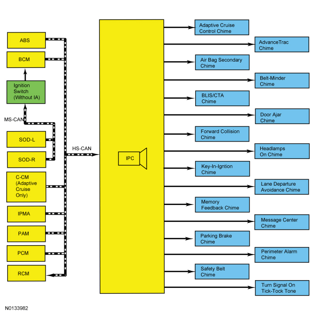
Warning Chimes
Overview
The warning chimes provide the driver with audible warnings that act as reminders and supplemental alerts to the visual IPC indications (gauges, indicators and message center warnings). The deviation from this strategy is the air bag warning chime, which alerts the driver that the primary alerting system (air bag warning indicator) does not operate. The IPC controls all warning chimes based on messages received from external modules.
The warning chimes are an integral part of the IPC, which receives and acts upon much of the same input information used to operate the IPC gauges, indicators, warning indicators and message center warnings. The IPC prioritizes the chimes according to a preset hierarchy programmed into the IPC software. When more than one chime request is received by the IPC, the most important chime sounds. If a lower priority chime is currently sounding, the higher priority request takes over and replaces the lower priority chime.
System Operation
System Diagram
Network Message Chart
Module Network Input Messages - IPC
Warning Chime Characteristics
The warning chimes use volume, chime frequency, length of time the chime sounds, decay of the chime tone and the number of chime tones to identify which chime is sounding. Most warning chimes have unique characteristics, however, there are chimes that do sound the same. For example, the parking brake warning chime and the key-in-ignition chime are repetitive 1 second chime tones that sound the same but the entry conditions for sounding the chime may differ. For additional information, refer to the component descriptions for each of the chimes. The chime characteristics are defined by 3 basic chime types:
- Repetitive
- Single tone
- Tick-tock (on-off)
Adaptive Cruise Control Warning Chime
The adaptive cruise control warning chime supplements the message center displays to draw the driver's attention to the need to intervene and take control of the vehicle. There are 2 levels of chime output (high priority and low priority) based upon the nature and urgency of the warning. The IPC sounds the appropriate warning chime when it receives the adaptive cruise control warning chime request (high priority chime) or adaptive cruise control message display (low priority chime) message from the C-CM.
The low priority adaptive cruise control warning chime is a single-tone chime that sounds to alert the driver that the adaptive cruise control system has shut itself off due to low vehicle speed (approximately 32 kmh [19.9 mph] ) and the driver needs to intervene if further braking is required or to resume the adaptive cruise control operation.
The high priority adaptive cruise control warning chime is also a single tone chime that is longer than the low priority chime. The chime increases in intensity and alerts the driver that the vehicle is approaching the vehicle ahead at a faster rate than the adaptive cruise control system can brake the vehicle and that the driver needs to apply the brakes to slow the vehicle down.
Air Bag Secondary Warning Chime
The air bag secondary warning chime warns that the air bag warning indicator LED is inoperative.
If the IPC detects a fault with the air bag warning indicator LED during the bulb prove out, the air bag secondary warning chime sounds five repetitive 1 second chime tones.
If the IPC detects a fault in the air bag warning indicator when a SRS fault condition exists and the RCM has sent the IPC the air bag indicator message, the air bag secondary warning chime sounds five repetitive 1 second chime tones.
Belt-Minder Feature
The Belt-Minder is configurable. Refer to Belt-Minder Deactivating/Activating.
The Belt-Minder feature supplements the current safety belt warning function and is enabled after the current safety belt warning is complete and receives the Belt-Minder warning request from the RCM. The Belt-Minder reminds the driver that the driver or front passenger safety belt is unbuckled by intermittently and simultaneously sounding a chime and illuminating the safety belt warning indicator in the IPC once the vehicle speed has exceeded 9.7 kmh (6 mph). The Belt-Minder remains active for 5 minutes from the time it is started. While activated, the Belt-Minder chime provides a series of 6 chimes/safety belt warning indicator flash sequences, which consist of a 1 second chime tone and safety belt warning indicator on/off state. The Belt-Minder chime and the safety belt warning indicator sound and flash for 6 seconds, then the chime stops and the safety belt warning indicator remains on for 25 seconds. The IPC repeats the chime cycle for 5 minutes.
If the vehicle speed drops below 4.8 kmh (3 mph) once the Belt-Minder chime has activated, the chime turns off and the safety belt warning indicator remains on. When the vehicle speed exceeds 9.7 kmh (6 mph) again, the Belt-Minder chime resumes.
NOTE: Whenever the vehicle is operated using MyKey, the RCM enables the Belt-Minder.
When MyKey is in use, the driver cannot configure the Belt-Minder off. Once the Belt-Minder is activated, the Belt-Minder continues to chime periodically (does not time out after 5 minutes) and the audio system is muted until the driver and passenger safety belts are fastened. For information on the MyKey feature, refer to the Owner's Literature.
BLIS / CTA Warning Chime
The BLIS / CTA warning chime sounds to alert the driver that a vehicle has been detected or that there is a system fault. The IPC receives the CTA information message from the BCM, which gateways the messages from the SOD-L and SOD-R.
The BLIS / CTA warning chime sounds for 1 second whenever the IPC receives the BLIS / CTA warning chime request.
Door Ajar Warning Chime
The door ajar warning chime warns that a door or the luggage compartment lid is ajar. The IPC receives the driver door, passenger door, left rear door, passenger rear door ajar and the luggage compartment lid ajar status from the BCM. When a door or the luggage compartment lid becomes ajar while the ignition is in RUN with vehicle speed greater than 5 kmh (3 mph), the IPC displays the appropriate door ajar warning message, illuminates the door ajar message center warning indicator and sounds a single 1.6 second chime tone.
Forward Collision Warning Chime
The forward collision warning chime warns that a forward collision potential has been detected or the C-CM detects a forward collision warning system concern. The IPC receives the forward collision warning chime request from the C-CM.
Once the forward collision system detects a possible forward collision, the C-CM sends the HUD module a message to flash the forward collision warning, a message to the ACM to mute the audio system and a message to the IPC to sound a 1.5 second chime tone.
The forward collision warning system and chime can be configured off using the message center. When MyKey is in use, the driver cannot configure the forward collision warning system or chime off. For information on the MyKey feature, refer to the Owner's Literature. For information on the forward collision configuration, Refer to Section 419-03C.
Headlamps On Warning Chime
The headlamps on warning chime warns that the headlamps are on when the driver door is ajar and the ignition is off. The IPC receives the headlamps on warning chime command from the BCM. The headlamps on warning chime sounds if the driver door is ajar, the headlamp switch is in the PARK or HEADLAMP position, and the ignition is off.
The chime sounds a repetitive 1.6 second chime tone for as long as the headlamps are on and the IPC receives the chime on command. The chime shuts off when battery saver has expired (approximately 30 minutes).
Key-In-Ignition Warning Chime
The key-in-ignition warning chime warns that the key is still in the ignition lock cylinder when the driver door is ajar (without IA ) or that the ignition is in the accessory state (with IA ). The IPC receives the key-in-ignition warning chime command from the BCM. The key-in-ignition warning chime sounds when the driver door is ajar, the key is in the ignition lock cylinder and in the off/lock or accessory position (without IA ) or when the ignition is in the accessory state (with IA ).
The chime sounds a repetitive 1 second chime tone for as long as the key is in the lock cylinder with the ignition off (except IA ) or the ignition in accessory mode (with IA ) with the door ajar. The chime shuts off when battery saver has expired (approximately 30 minutes).
Lane Departure Warning Chime
The lane departure warning chime sounds to alert the driver that they have removed their hands from the steering wheel. The IPC receives the lane departure warning chime request from the IPM-A. The image processing module receives a hands off status message from the IPM-A. The lane departure warning chime is repeated every 6 seconds or until the IPM-A detects that the driver has placed their hands back on the steering wheel.
Memory-Stored Feedback Chime
The memory-stored feedback chime informs the driver their preferences have been successfully programmed through the memory set procedure. The IPC receives the memory feedback request from the BCM. The BCM receives the memory feedback request from the DSM.
The chime sounds for 0.1 second when the IPC receives a successful memory state change message.
Message Center Warning Chime
The message center warning chime feature draws the driver's attention to the message center display to view a new warning message. The IPC provides a single 1.6 second tone whenever a new warning message is displayed in the message center. If multiple warning messages are present, the IPC sounds a chime for each of the warning messages that are present as they cycle through the message center display.
Parking Brake Warning Chime
The parking brake warning chime warns that the parking brake is engaged when the vehicle is in motion. The parking brake warning chime sounds if the ignition is in ON, the parking brake is engaged, and the vehicle speed is greater than 5 kmh (3 mph). The parking brake warning chime stops sounding and resets if the parking brake is released, the ignition is on, if the vehicle speed is less than 5 kmh (3 mph), or after 90 seconds from the time the chime is activated. The IPC receives the park brake chime request from the BCM. The chime sounds a repetitive 1 second chime tone for as long as the parking brake is applied and the IPC receives the park brake chime request.
Perimeter Alarm Warning Chime
The perimeter alarm warning chime alerts the driver the perimeter alarm is armed when the driver door is unlocked with a key. The warning chime is only functional when a key is used to unlock the driver door. If the key fob or keypad (if equipped) is used to unlock the door, the perimeter alarm is disarmed and the warning chime does not sound. The warning chime sounds for 12 seconds when the driver door is opened and turns off when the perimeter alarm is disarmed (either by using the key fob, keypad or turning the key to the ON position). The chime sounds 2 chime tones for the first 6 seconds followed by 3 chime tones for the next 4 seconds and finally 4 chime tones for the last 3 seconds. After the 12 second warning chime duration, the warning chime stops sounding and the perimeter alarm activates, sounding the horn and flashing the turn signal lamps. The IPC receives the perimeter alarm chime request from the BCM.
Safety Belt Warning Chime
The safety belt warning chime warns that the safety belt is not fastened. The safety belt warning chime sounds repetitive 1.6 second tones for 6 seconds when the driver safety belt is not fastened and the ignition is transitioned from OFF or accessory to ON or START. The safety belt warning chime stops sounding when the safety belt is fastened, when the ignition is transitioned from ON or START to OFF or accessory, or when the chime has sounded for approximately 6 seconds. The IPC receives the safety belt warning chime request from the RCM.
Service AdvanceTrac Warning Chime
The service AdvanceTrac warning chime warns that the ABS module has detected a fault condition in the stability-traction control system. The ABS module provides the AdvanceTrac warning chime request to the IPC.
If a fault condition exists in the stability-traction control system, the ABS module sends the IPC the AdvanceTrac warning chime request to display SERVICE ADVANCETRAC in the message center and sound the chime. The chime sounds three repetitive 1.0 second chime tones 8 seconds after the IPC has stabilized in its normal operational mode, a fault condition has been detected by the ABS and a chime request has been received by the IPC.
Turn Signal On Chime
The IPC provides a repetitive tick-tock along with visual RH/LH turn indicator to inform the driver the turn signal or hazard lamp function is on. The IPC receives the turn indicator command from the BCM.
Turn Signal Left On Chime
The IPC uses both odometer and steering wheel switch turn signal messages to control the turn signal left on chime. The IPC receives the steering wheel switch turn signal message from the BCM and the odometer message from the PCM. When the vehicle is driven with the turn signal on for more than 193 km (2.0 miles), the IPC sounds a repetitive 1.0 second chime.

 Diagnosis and Testing
Instrumentation, Message Center and Warning Chimes
Special Tool(s)
DTC Chart(s)
Diagnostics in this manual assume a certain skill level and knowledge of
Ford-specific diagnostic practices. REFER to& ...
Other materials:
Cleaning the exterior
Wash your vehicle regularly with cool or lukewarm water and a neutral
pH shampoo, such as Motorcraft® Detail Wash.
• Never use strong household detergents or soap, such as dish washing
or laundry liquid. These products can discolor and spot painted
surfaces.
• Never wash a vehicle that ...
General Procedures, Removal and Installation
GENERAL PROCEDURES
Wiper Blade and Pivot Arm Adjustment
Cycle and park the windshield wipers.
Verify that the RH and LH wiper blade tips are aligned to the "I" marks
on the lower windshield glass.
NOTE: Make sure there is no mechanical binding in the linkage
preventing the wiper arm ...
Interior Lighting
DESCRIPTION AND OPERATION
Interior Lighting
Overview
The interior lighting system consists of:
Courtesy lamps
Demand lamps
Ambient lighting (if equipped)
The courtesy lamps subsystem consists of:
Interior lamps
Puddle lamps
Door ajar switches (integrated into the door latches)
Instrument p ...
