Instrumentation, Message Center and Warning Chimes
Special Tool(s)

DTC Chart(s)
Diagnostics in this manual assume a certain skill level and knowledge of Ford-specific diagnostic practices. REFER to Section 100-00 for information regarding these diagnostic practices.
DTC Chart - IPC
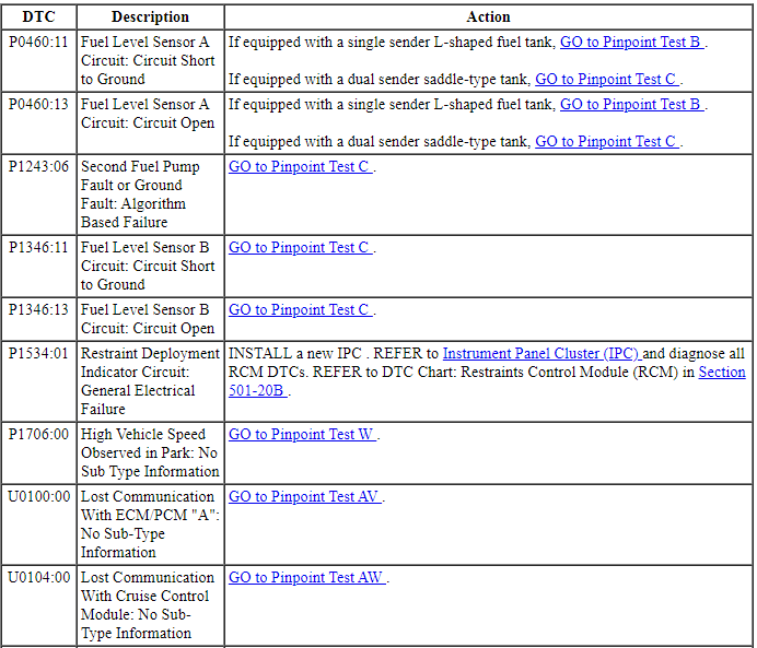
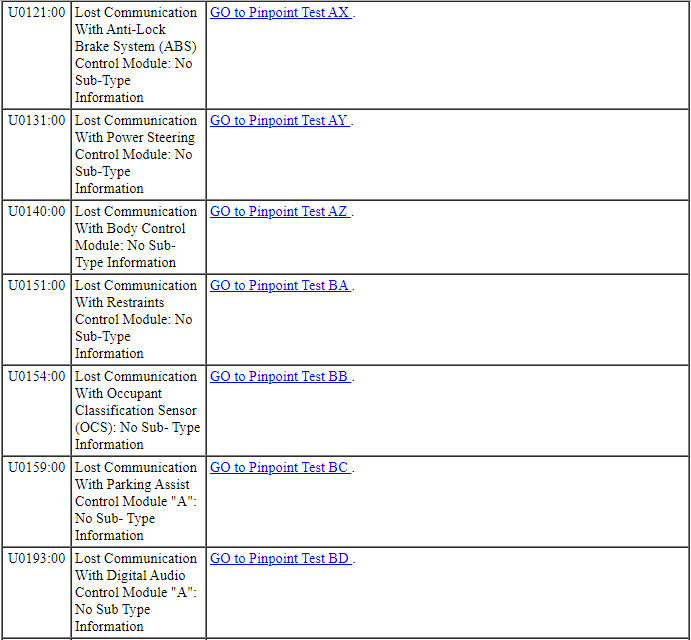
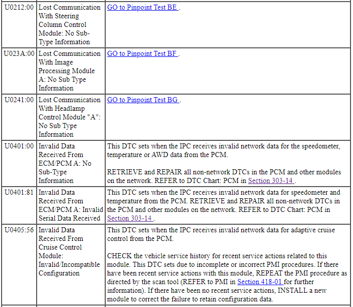
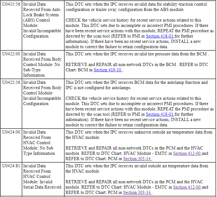
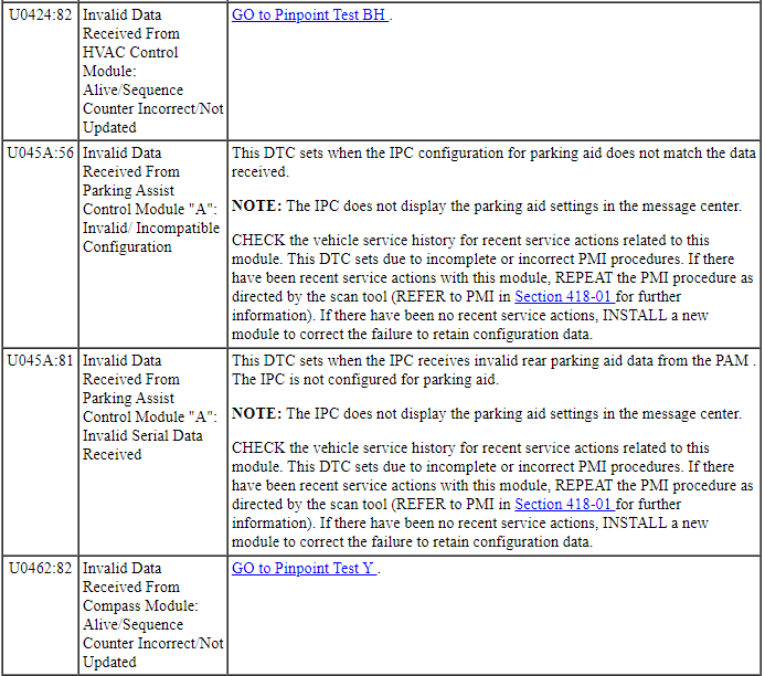
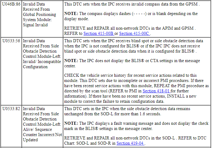
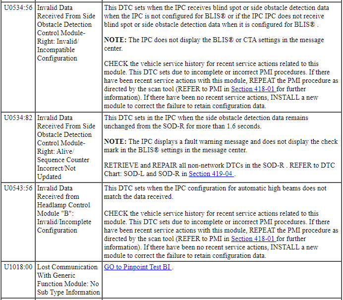
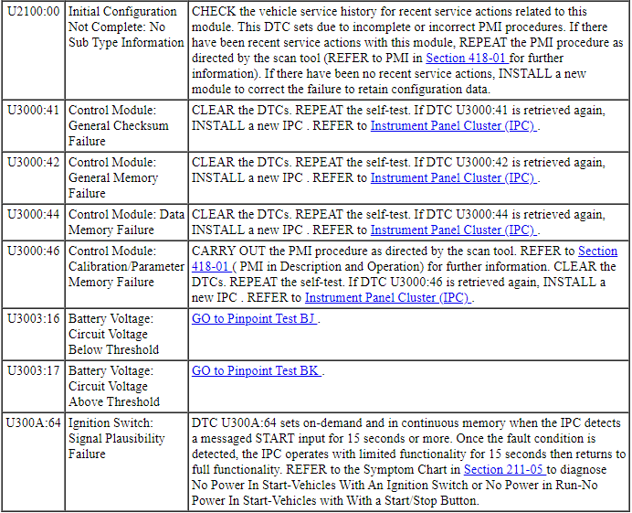
Related Module DTC Chart(s)
Diagnostics in this manual assume a certain skill level and knowledge of Ford-specific diagnostic practices. REFER to Section 100-00 for information regarding these diagnostic practices.
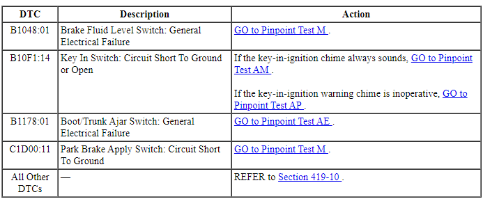
BCM DTC Chart
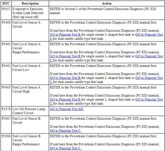
PCM DTC Chart

SCCM DTC Chart

Symptom Chart(s)
Diagnostics in this manual assume a certain skill level and knowledge of Ford-specific diagnostic practices. Refer to Diagnostic Methods in Section 100-00 for information about these practices.
Symptom Chart - IPC
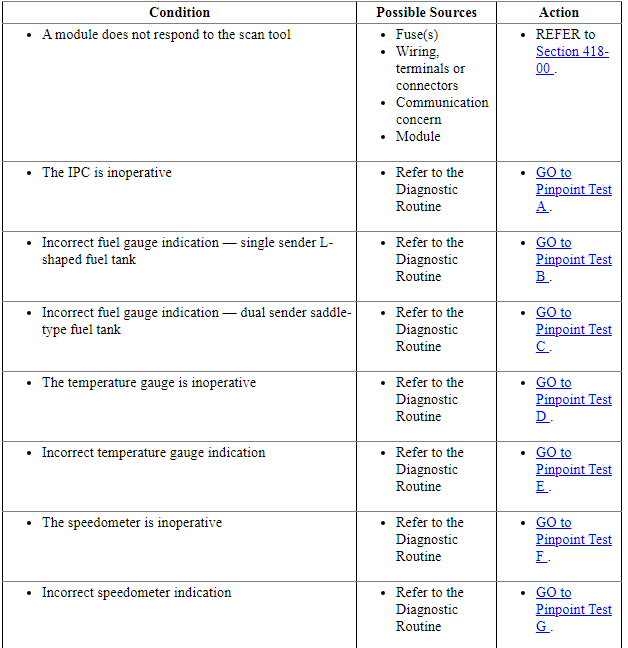
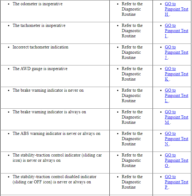
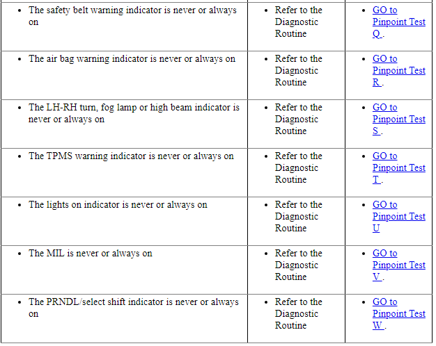
Symptom Chart - Information And Message Center
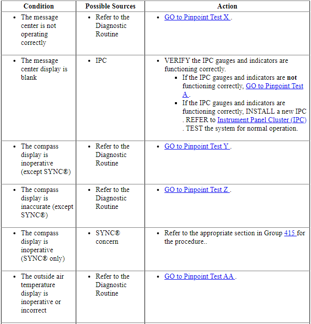
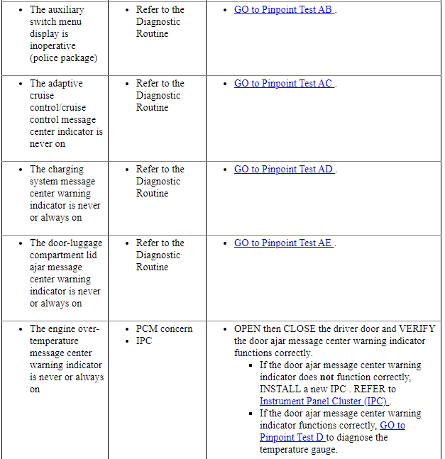
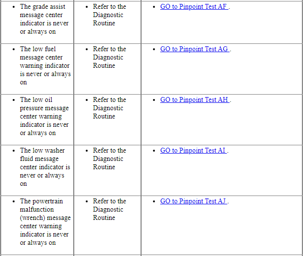
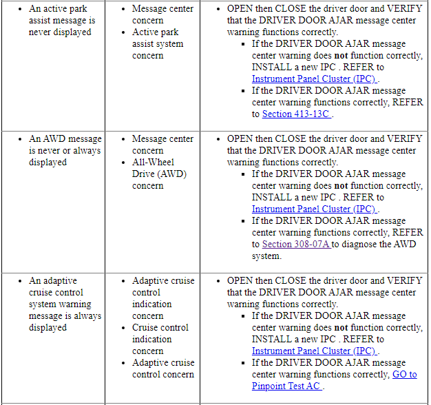
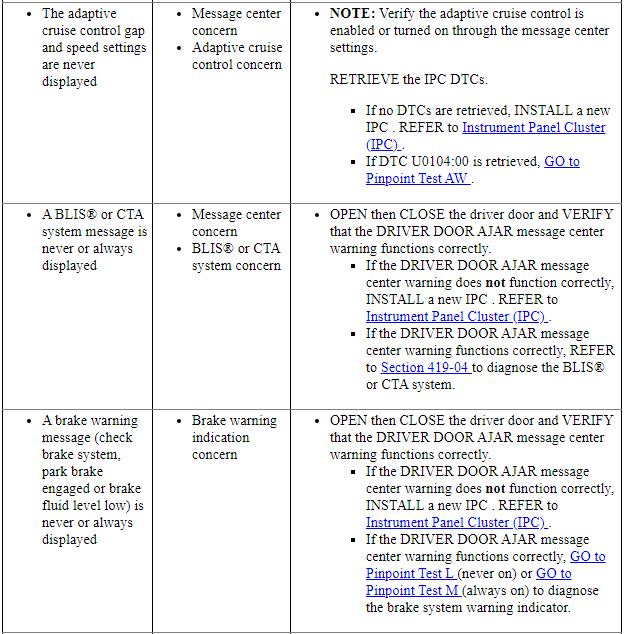
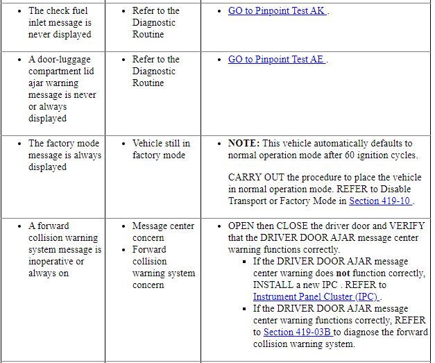
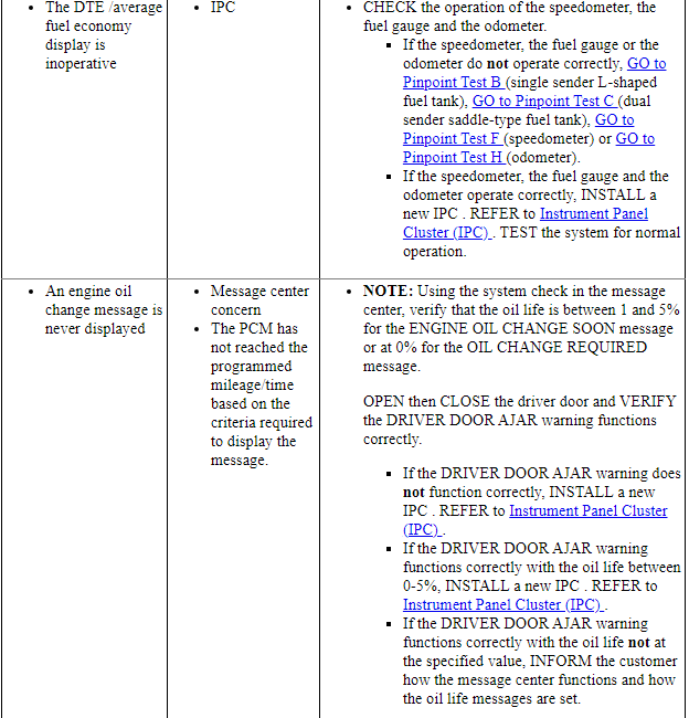
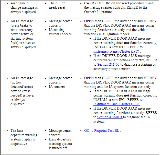
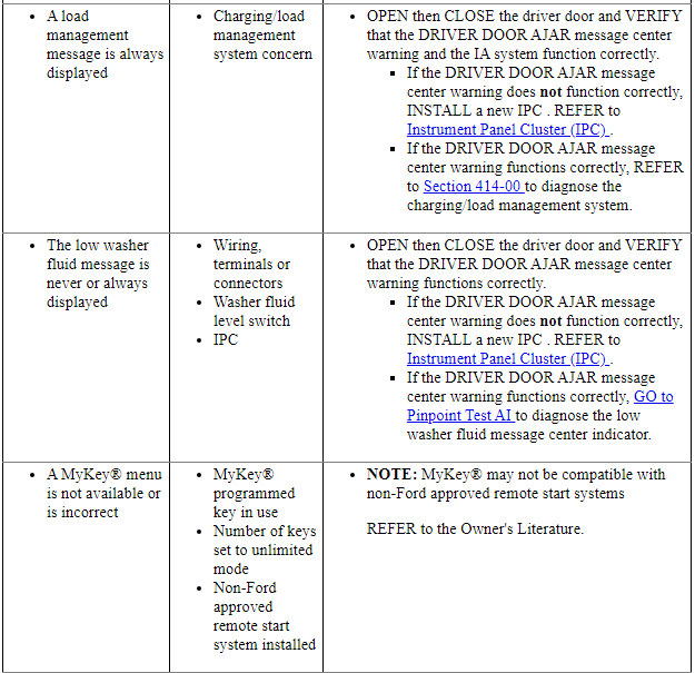
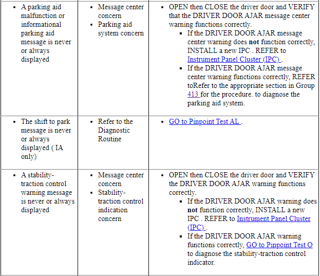
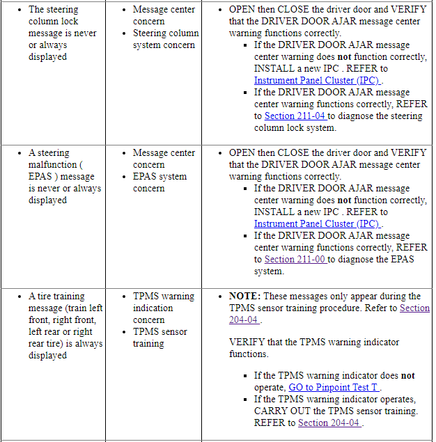
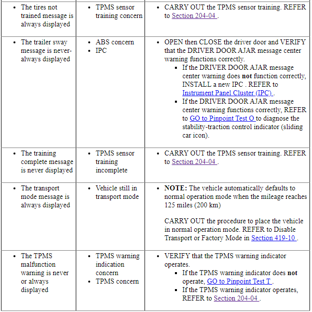
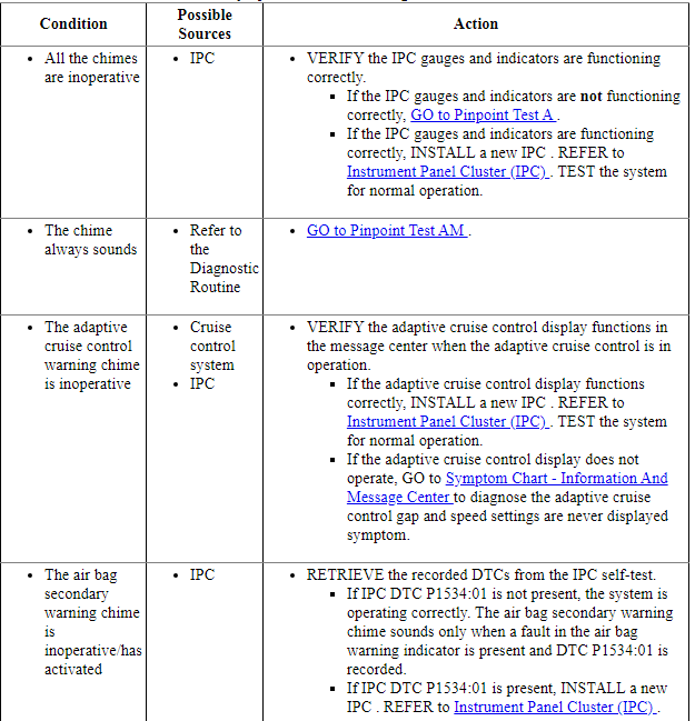
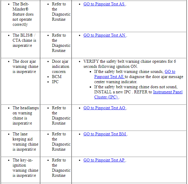
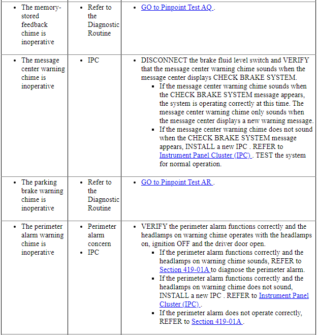
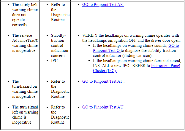
Symptom Chart - Warning Chimes
Pinpoint Tests
Pinpoint Test A: The IPC Is Inoperative
Diagnostic Overview
Diagnostics in this manual assume a certain skill level and knowledge of Ford-specific diagnostic practices. Refer to Diagnostic Methods in Section 100-00 for information about these practices.
Normal Operation and Fault Conditions
The IPC receives a hot at all times voltage from the BCM. The IPC receives the ignition status message from the BCM over the HS-CAN.
-
Possible Sources
- Communication concern
- IPC
Visual Inspection and Diagnostic Pre-checks
Inspect the BCM fuse 23 (15A).
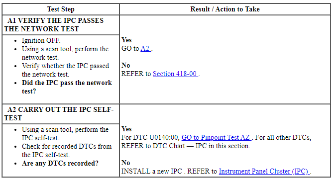
PINPOINT TEST A: THE IPC IS INOPERATIVE
Pinpoint Test B: Incorrect Fuel Gauge Indication - Single Sender L-Shaped Tank
Diagnostic Overview
Diagnostics in this manual assume a certain skill level and knowledge of Ford-specific diagnostic practices. Refer to Diagnostic Methods in Section 100-00 for information about these practices.
Refer to Wiring Diagrams Cell 60, Instrument Cluster for schematic and connector information.
Normal Operation and Fault Conditions
The fuel gauge uses inputs from the fuel pump assembly and the fuel level sensor to provide the fuel level indication. For information on the fuel gauge and fuel level sender, REFER to Fuel Gauge and Fuel Level Sender in Instrument Panel Cluster (IPC).
NOTE: A slight fluctuation in the fuel gauge needle is normal on the optional (video display) IPC. Do not fault the IPC for this concern.
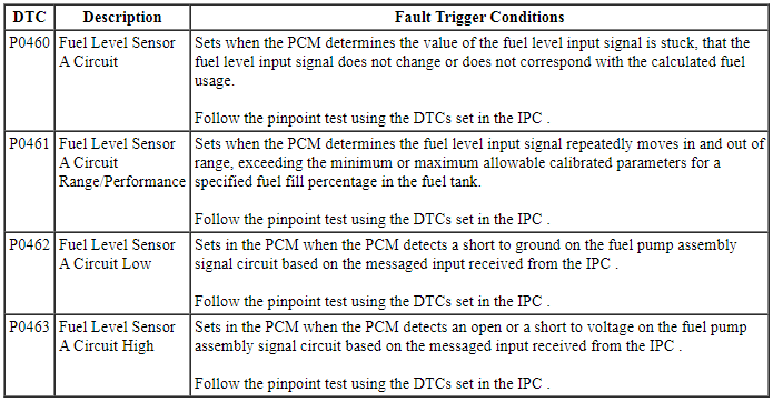
IPC DTC Fault Trigger Conditions

PCM Fault Trigger Conditions
-
Possible Sources
- Wiring, terminals or connectors
- Fuel pump assembly
- Fuel level sensor (float and card)
- Fuel tank
- IPC
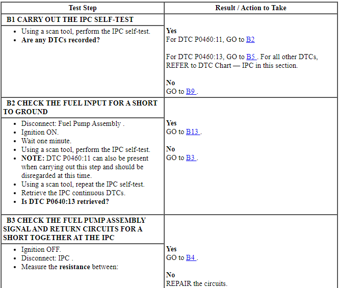
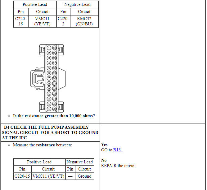
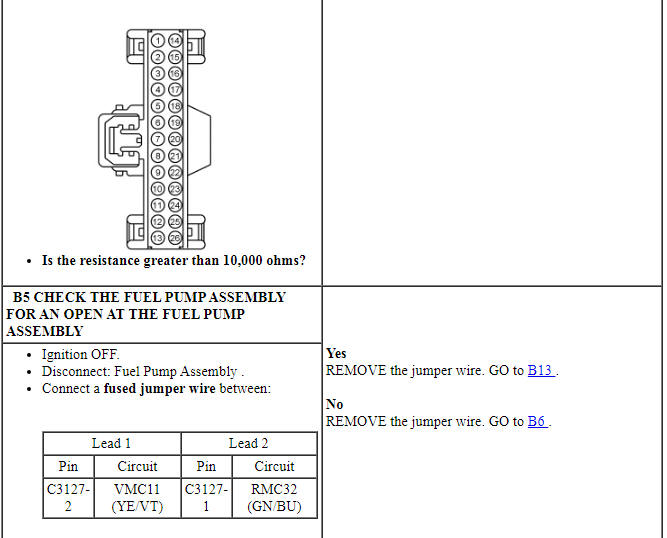
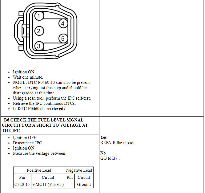
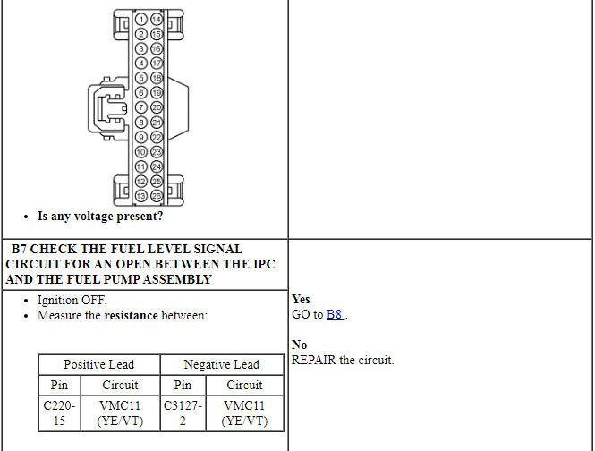
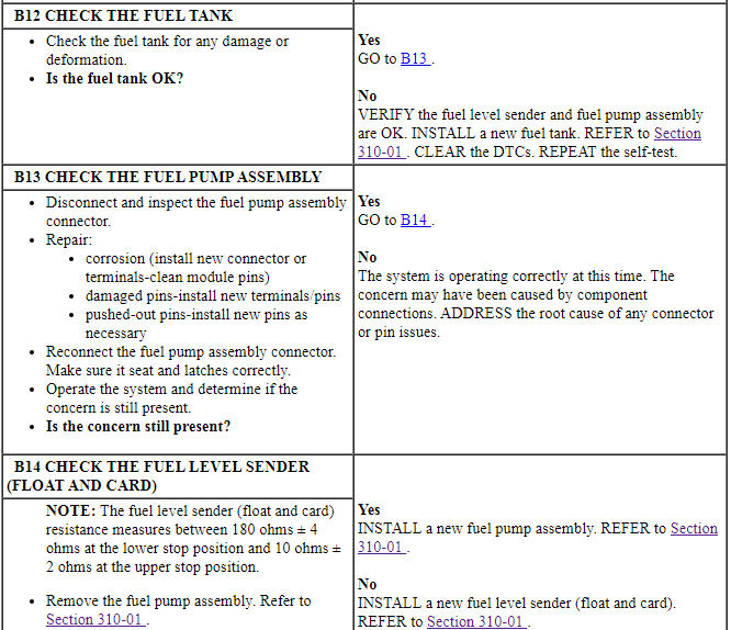
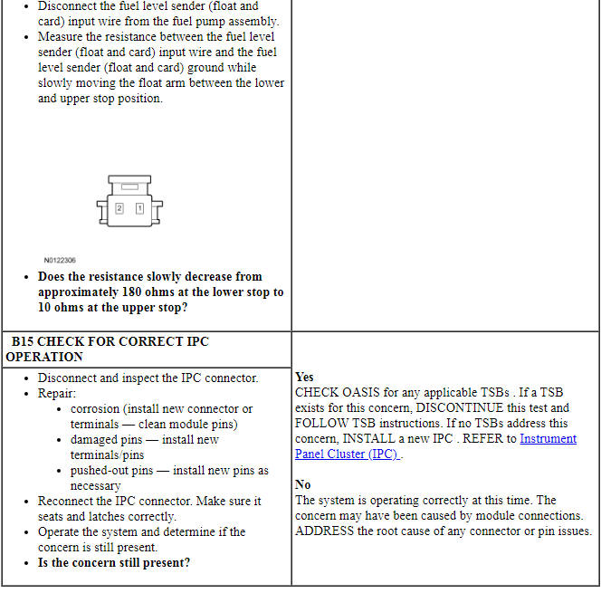
PINPOINT TEST B: INCORRECT FUEL GAUGE INDICATION - SINGLE SENDER L-SHAPED TANK
NOTE: Following any fuel gauge repairs, remove fuse 23 (15A) for one minute then reinstall to reset the fuel gauge timers.
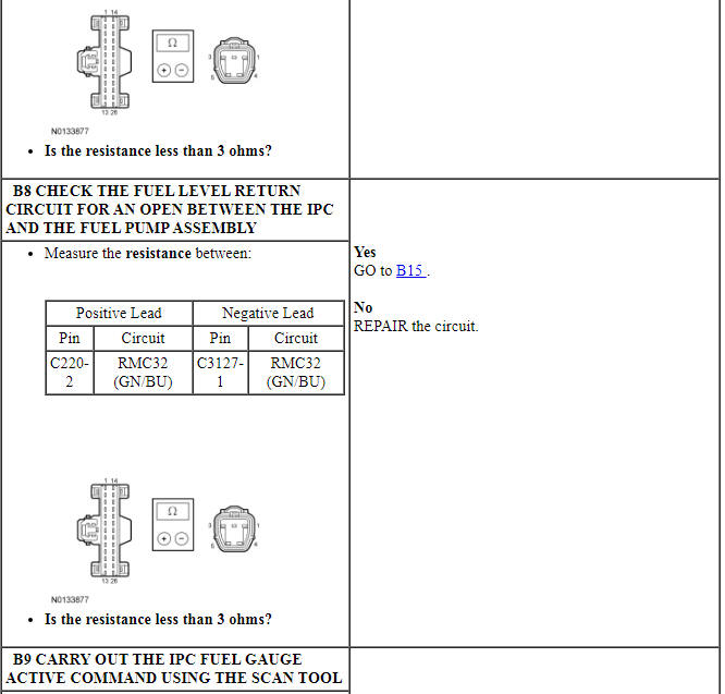
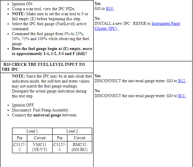
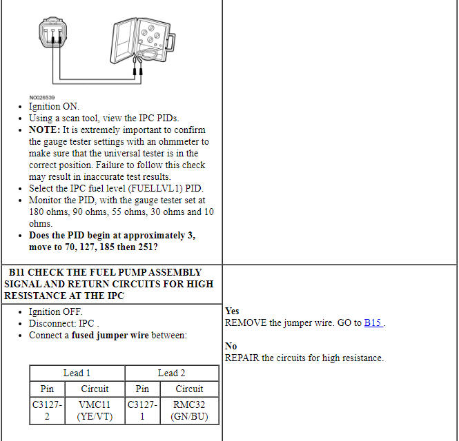
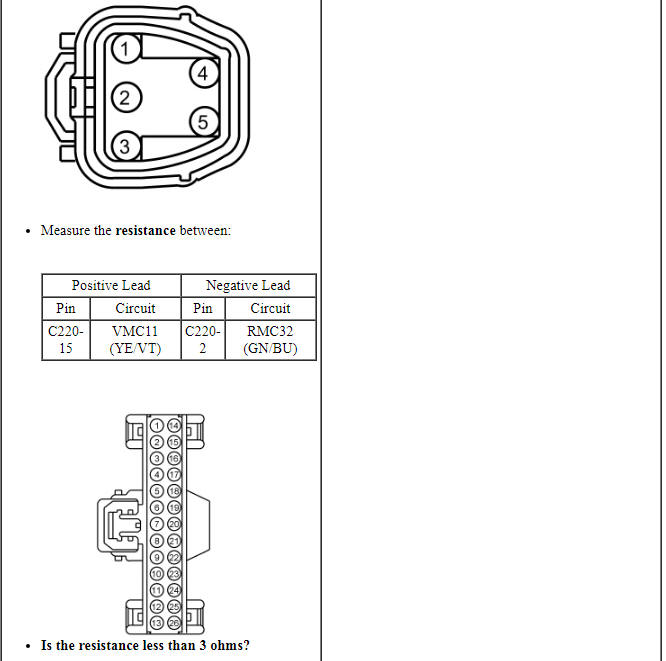
Pinpoint Test C: Incorrect Fuel Gauge Indication - Dual Sender Saddle-Type Tank
Diagnostic Overview
Diagnostics in this manual assume a certain skill level and knowledge of Ford-specific diagnostic practices. Refer to Diagnostic Methods in Section 100-00 for information about these practices.
Refer to Wiring Diagrams Cell 60, Instrument Cluster for schematic and connector information.
Normal Operation and Fault Conditions
The fuel gauge uses inputs from the fuel pump assembly and the fuel level sensor to provide the fuel level indication. For information on the fuel gauge and fuel level sender, REFER to Fuel Gauge and Fuel Level Sender in Instrument Panel Cluster (IPC).
NOTE: A slight fluctuation in the fuel gauge needle is normal on the optional (video display) IPC. Do not fault the IPC for this concern.
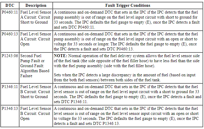
IPC DTC Fault Trigger Conditions
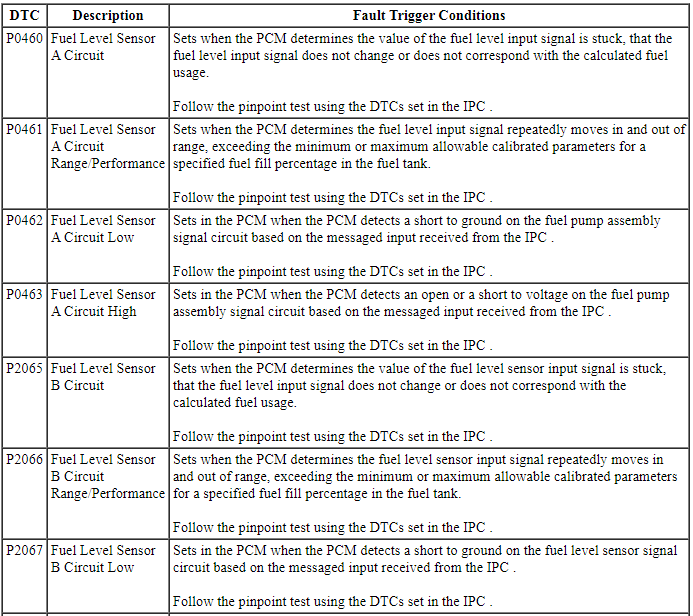
PCM Fault Trigger Conditions

-
Possible Sources
- Wiring, terminals or connectors
- Fuel pump assembly
- Fuel level sensor (float and card)
- Fuel tank transfer tube
- Fuel lines
- Fuel tank
- IPC
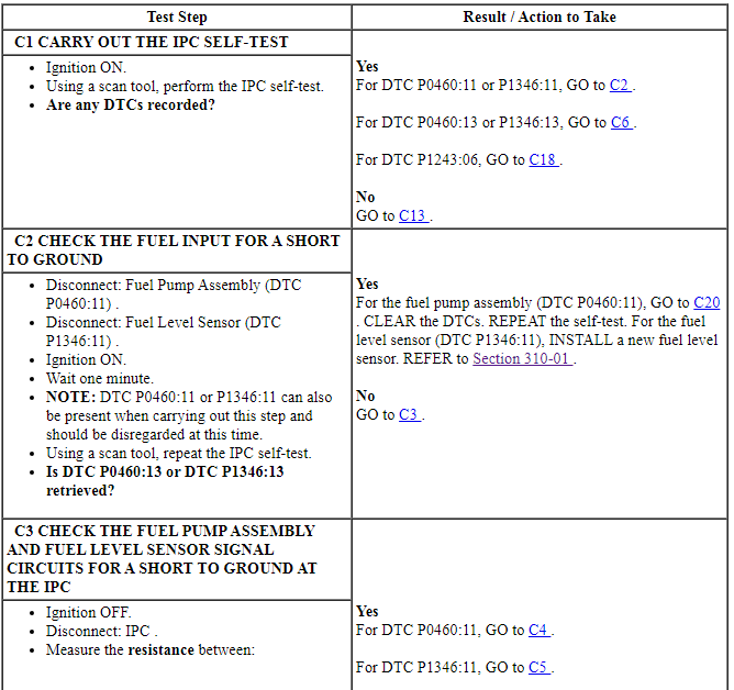
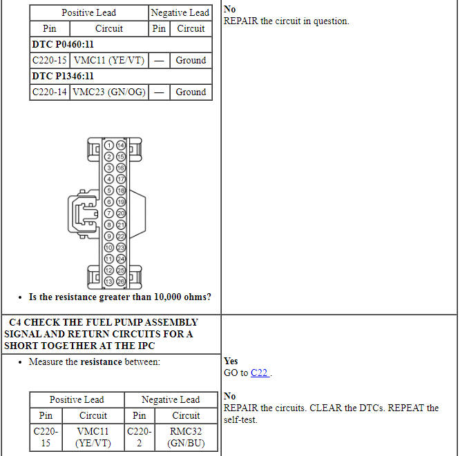
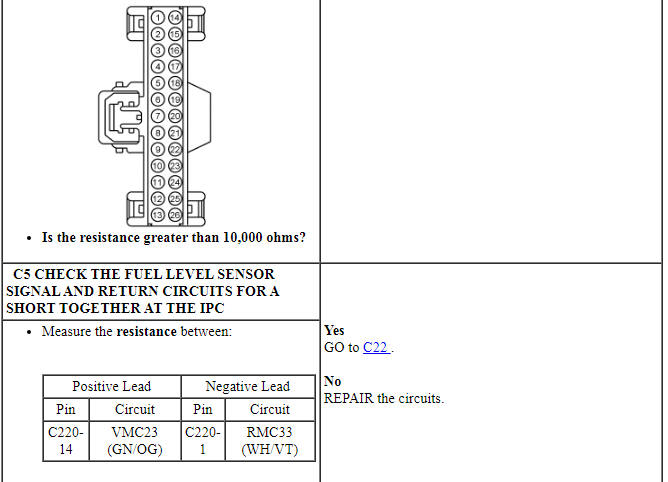
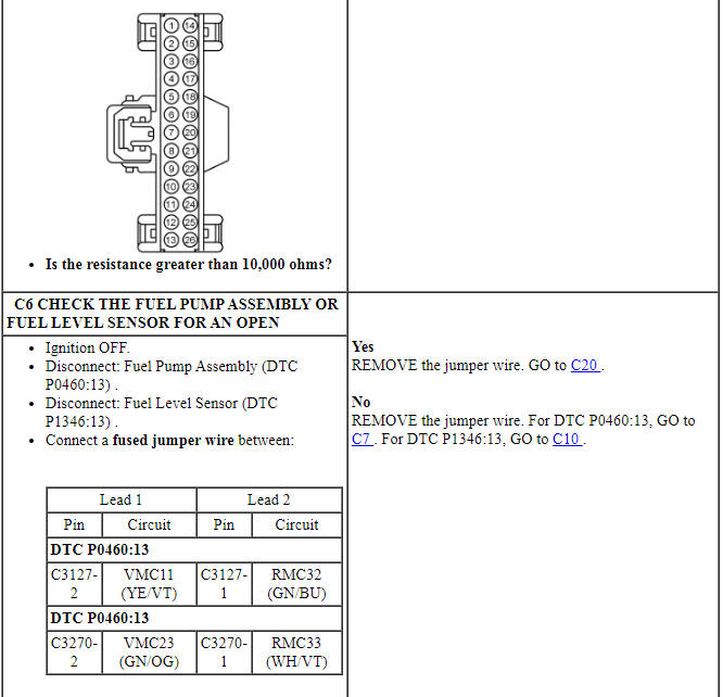
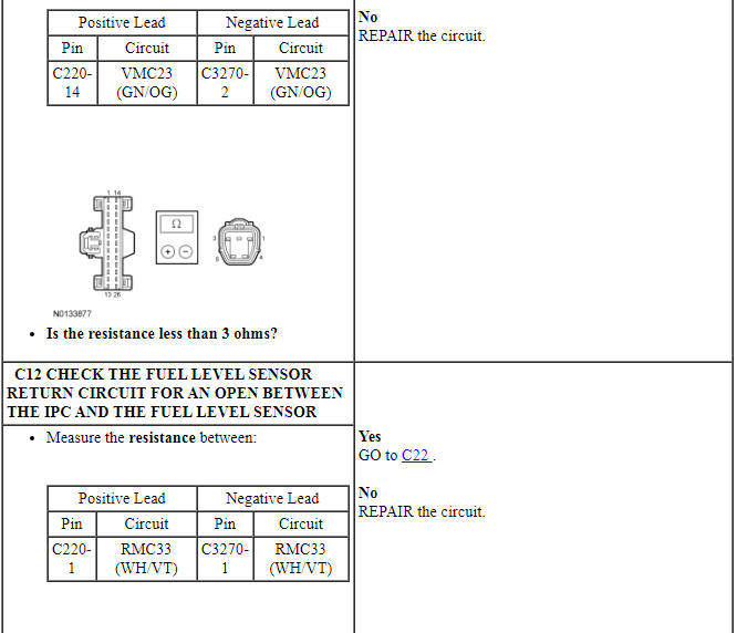
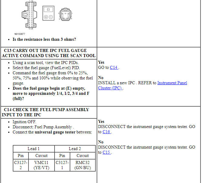
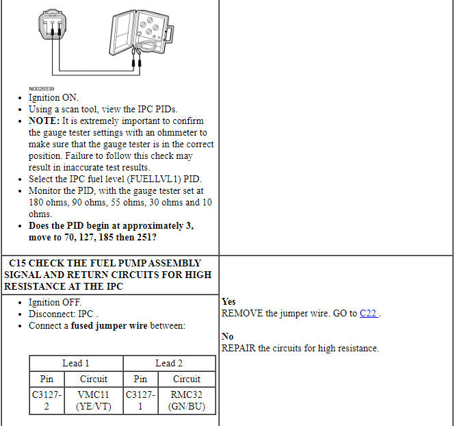
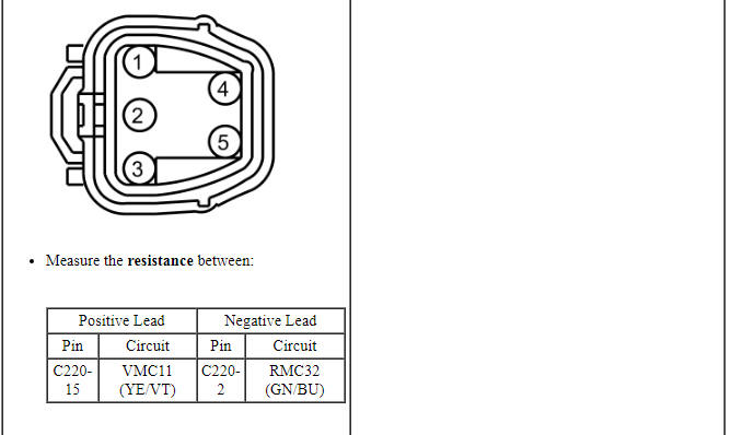
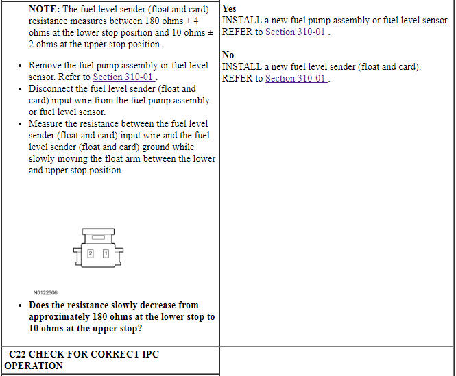
PINPOINT TEST C: INCORRECT FUEL GAUGE INDICATION - DUAL SENDER SADDLE-TYPE TANK
NOTE: Following any fuel gauge repairs, remove fuse 23 (15A) for one minute then reinstall to reset the fuel gauge timers.
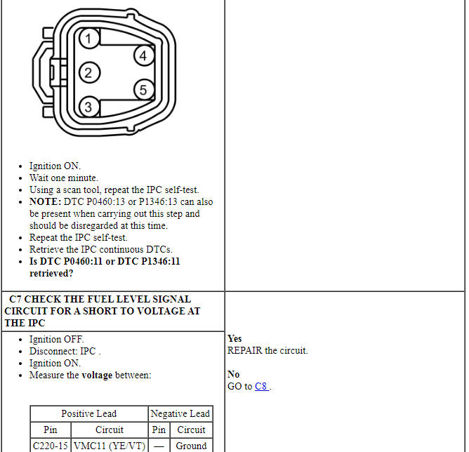
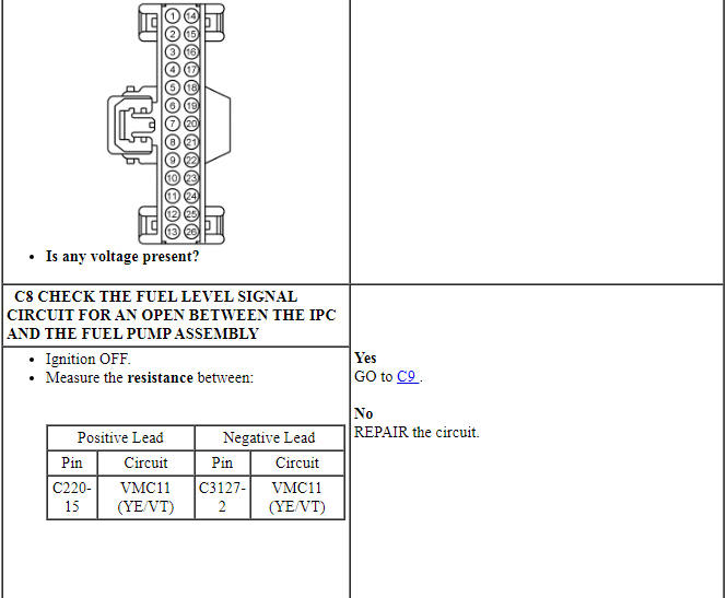
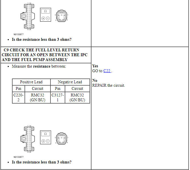
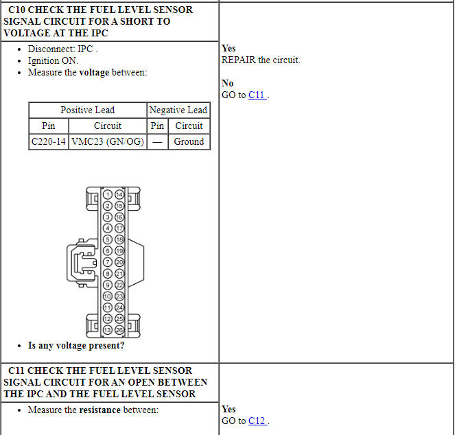
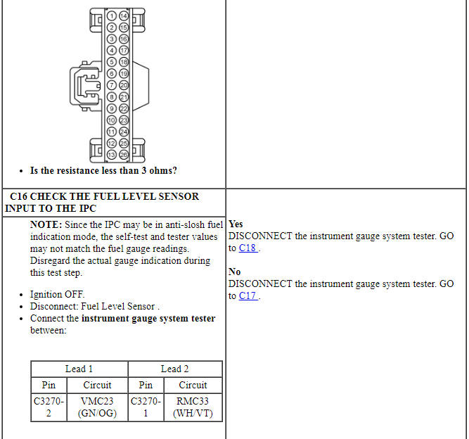
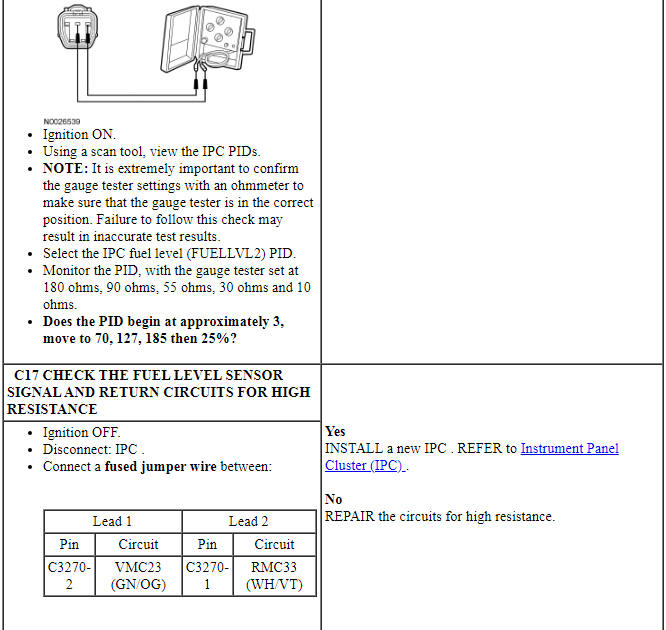
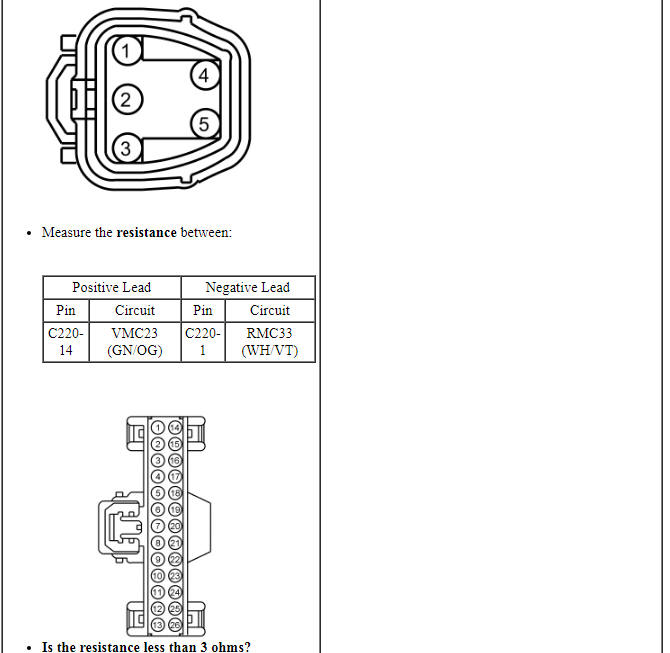
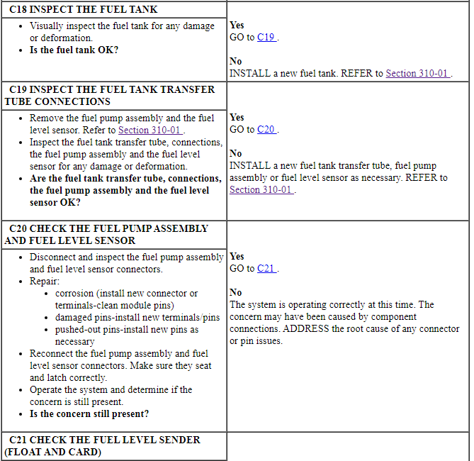
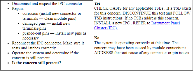
Pinpoint Test D: The Temperature Gauge Is Inoperative
Diagnostic Overview
Diagnostics in this manual assume a certain skill level and knowledge of Ford-specific diagnostic practices. Refer to Diagnostic Methods in Section 100-00 for information about these practices.
Normal Operation and Fault Conditions
REFER to Temperature Gauge in Instrument Panel Cluster (IPC).
NOTE: If DTC U0100:00 is set in the IPC, other observable symptoms may be an inoperative tachometer, speedometer or odometer.
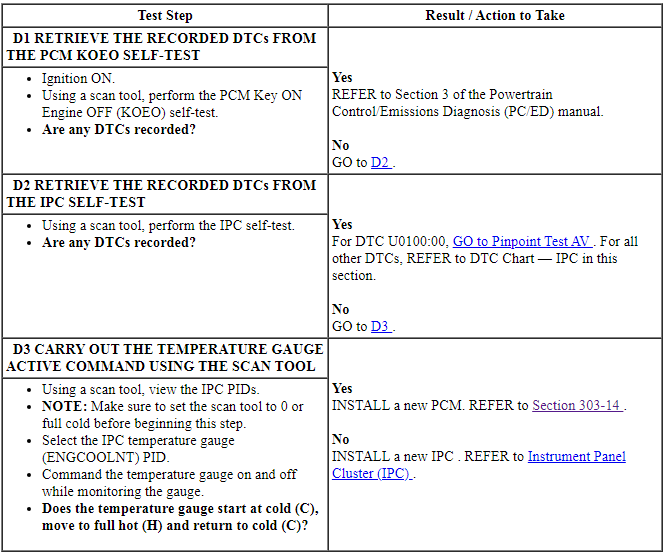
If the IPC does not receive the engine coolant temperature message from the PCM for more than 5 seconds, the IPC sets DTC U0100:00 in continuous memory and defaults the temperature gauge to cold (C). If the engine coolant temperature message is deemed invalid by the IPC for 5 seconds or more, the IPC sets DTC U0401:81 and defaults the temperature gauge to cold (C).
-
Possible Sources
- PCM
- IPC
PINPOINT TEST D: THE TEMPERATURE GAUGE IS INOPERATIVE
Pinpoint Test E: Incorrect Temperature Gauge Indication
Diagnostic Overview
Diagnostics in this manual assume a certain skill level and knowledge of Ford-specific diagnostic practices. Refer to Diagnostic Methods in Section 100-00 for information about these practices.
Normal Operation and Fault Conditions
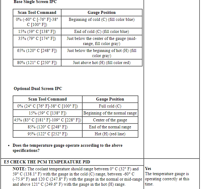
REFER to Temperature Gauge in Instrument Panel Cluster (IPC).
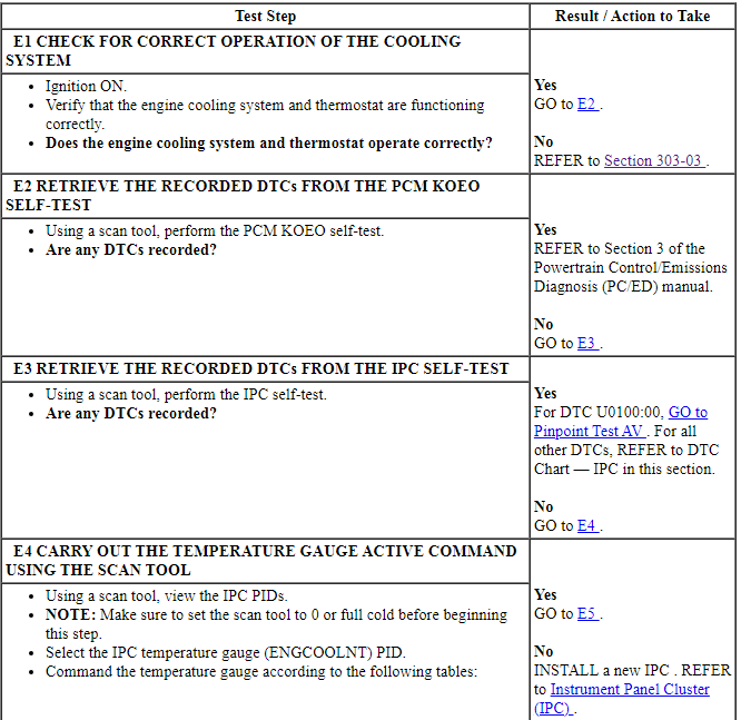
If the engine coolant temperature message is missing for 5 seconds or less or if the IPC receives invalid engine temperature data for 5 seconds or less, the IPC defaults the temperature gauge to the last setting, based upon the last known good temperature status message.
-
Possible Sources
- Engine cooling system concern
- PCM input concern
- IPC
PINPOINT TEST E: INCORRECT TEMPERATURE GAUGE INDICATION

Pinpoint Test F: The Speedometer Is Inoperative
Diagnostic Overview
Diagnostics in this manual assume a certain skill level and knowledge of Ford-specific diagnostic practices. Refer to Diagnostic Methods in Section 100-00 for information about these practices.
Normal Operation and Fault Conditions
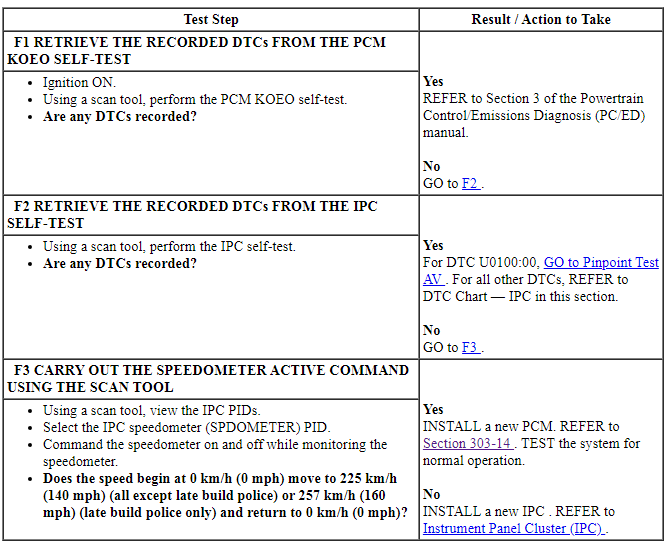
REFER to Speedometer in Instrument Panel Cluster (IPC).
NOTE: If DTC U0100:00 is set in the IPC, other observable symptoms may be an inoperative tachometer, temperature gauge or odometer.
If the IPC does not receive the vehicle speed data from the PCM for more than 5 seconds, the IPC sets DTC U0100:00 in continuous memory and defaults the speedometer to 0 km/h (0 mph). If the vehicle speed data is deemed invalid by the IPC for 5 seconds or more, the IPC sets DTC U0401:81 and defaults the speedometer to 0 km/h (0 mph).
-
Possible Sources
- PCM
- IPC
PINPOINT TEST F: THE SPEEDOMETER IS INOPERATIVE
Pinpoint Test G: Incorrect Speedometer Indication
Diagnostic Overview
Diagnostics in this manual assume a certain skill level and knowledge of Ford-specific diagnostic practices. Refer to Diagnostic Methods in Section 100-00 for information about these practices.
Normal Operation and Fault Conditions
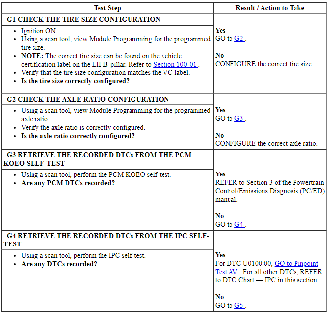
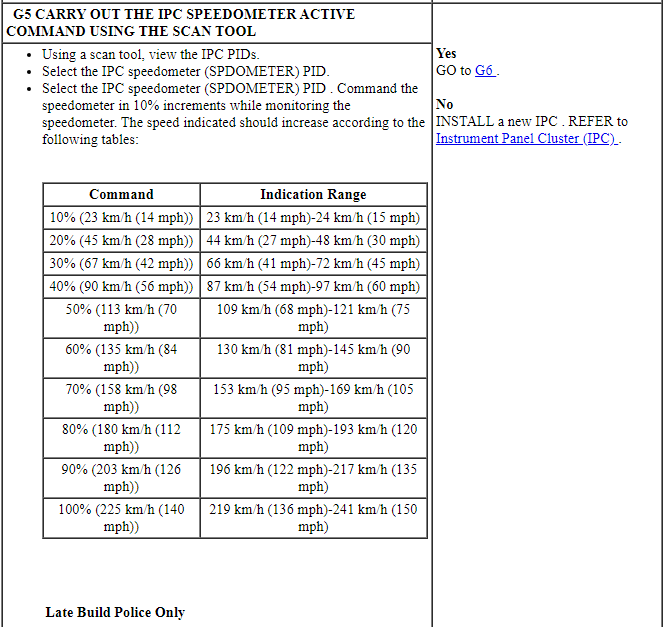
REFER to Speedometer in Instrument Panel Cluster (IPC).
If the vehicle speed data is missing for 5 seconds or less or if the IPC receives invalid vehicle speed data for 5 seconds or less, the IPC defaults the speedometer to the last setting, based upon the last known good vehicle speed message.
-
Possible Sources
- Tire size configuration
- Axle ratio configuration
- PCM input concern
- IPC
Visual Inspection and Diagnostic Pre-checks
Verify that the tire size on the vehicle matches the tire size listed on the VC label. REFER to VC Codes in Section 100-01.
PINPOINT TEST G: INCORRECT SPEEDOMETER INDICATION
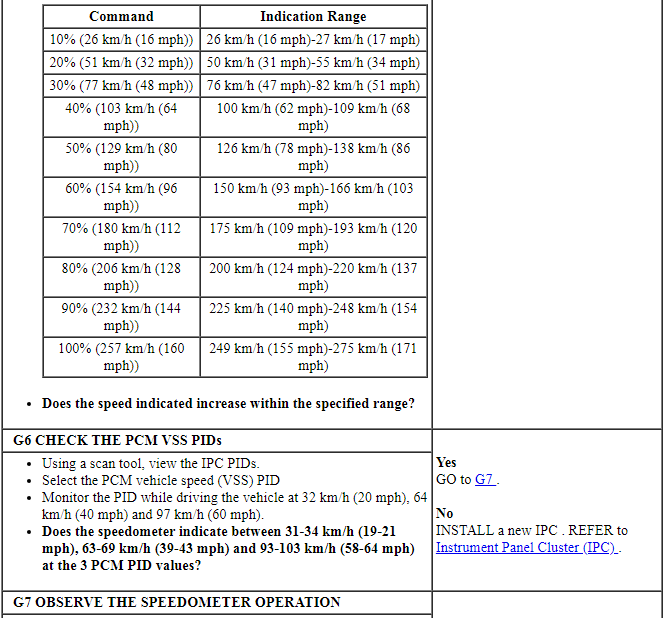

Pinpoint Test H: The Odometer Is Inoperative
Diagnostic Overview
Diagnostics in this manual assume a certain skill level and knowledge of Ford-specific diagnostic practices. Refer to Diagnostic Methods in Section 100-00 for information about these practices.
Normal Operation and Fault Conditions
REFER to Odometer in Instrument Panel Cluster (IPC).
If the odometer count message is missing for 5 seconds or less, the IPC defaults the odometer to the last display, based upon the last known good odometer rolling count message. If the IPC does not receive the odometer rolling count data from the PCM for more than 5 seconds, the IPC sets DTC U0100:00 in continuous memory and defaults the odometer display to all dashes (-----).
If the odometer count message is deemed invalid by the IPC, the IPC sets DTC U0401:00 and defaults the odometer display to all dashes (-----). If the NVM becomes corrupted or if any NVM failure occurs, the IPC sets DTC U3000:44 and displays ERROR in the message center display.
-
Possible Sources
- PCM
- IPC
PINPOINT TEST H: THE ODOMETER IS INOPERATIVE
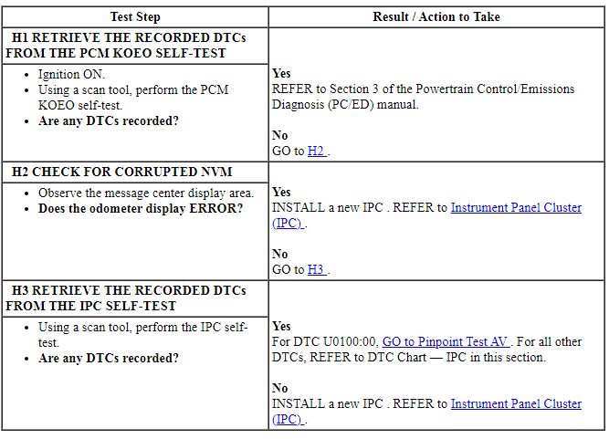
Pinpoint Test I: The Tachometer Is Inoperative
Diagnostic Overview
Diagnostics in this manual assume a certain skill level and knowledge of Ford-specific diagnostic practices. Refer to Diagnostic Methods in Section 100-00 for information about these practices.
Normal Operation and Fault Conditions
REFER to Tachometer in Instrument Panel Cluster (IPC).
If the IPC does not receive the engine rpm data from the PCM for more than 5 seconds, the IPC sets DTC U0100:00 in continuous memory and defaults the tachometer to 0 rpm.
-
Possible Sources
- PCM
- IPC
PINPOINT TEST I: THE TACHOMETER IS INOPERATIVE
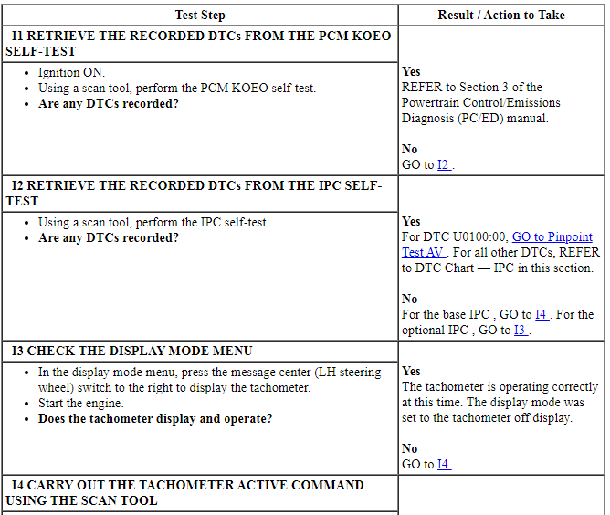

Pinpoint Test J: Incorrect Tachometer Indication
Diagnostic Overview
Diagnostics in this manual assume a certain skill level and knowledge of Ford-specific diagnostic practices. Refer to Diagnostic Methods in Section 100-00 for information about these practices.
Normal Operation and Fault Conditions
REFER to Tachometer in Instrument Panel Cluster (IPC).
If the rpm data is missing for 5 seconds or less or if the IPC receives invalid rpm data for 5 seconds or less, the IPC defaults the tachometer to the last setting, based upon the last good message received. If the IPC does not receive the engine rpm data from the PCM for 5 seconds or less, the IPC defaults the tachometer to the last setting, based upon the last known good rpm message. If the engine rpm message is missing or invalid for 5 seconds or less, the gauge can appear to freeze or become erratic.
-
Possible Sources
- PCM input concern
- IPC
PINPOINT TEST J: INCORRECT TACHOMETER INDICATION
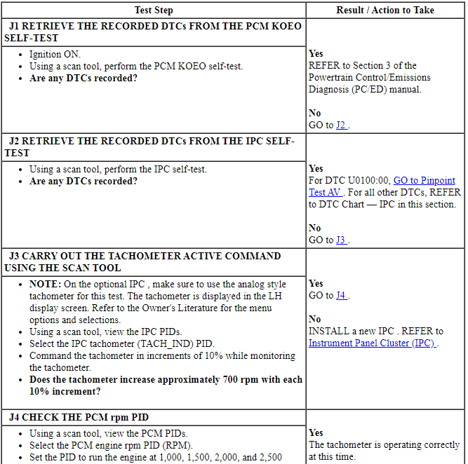

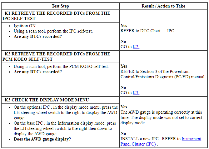
Pinpoint Test K: The AWD Gauge Is Inoperative
Diagnostic Overview
Diagnostics in this manual assume a certain skill level and knowledge of Ford-specific diagnostic practices. Refer to Diagnostic Methods in Section 100-00 for information about these practices.
Normal Operation and Fault Conditions
REFER to AWD gauge in Instrument Panel Cluster (IPC).
NOTE: NOTE: If DTC U0100:00 sets in the IPC, other observable symptoms can be an inoperative tachometer, temperature gauge or odometer.
If the AWD lock torque actual, wheel torque or vehicle speed message is missing for 5 seconds or less or if the IPC receives invalid torque data for 5 seconds or less, the IPC defaults the display fill area in front of the front wheels and behind the rear wheels to the last setting based upon that last known good message.
If the IPC does not receive the AWD lock torque actual, wheel torque or vehicle speed message from the AWD for more than 5 seconds, the IPC sets DTC U0100:00 in continuous memory and defaults the display fill area in front of the front wheels and behind the rear wheels off.
-
Possible Sources
- AWD system concern
- IPC
PINPOINT TEST K: THE AWD GAUGE IS INOPERATIVE
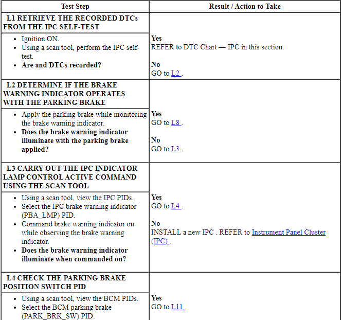
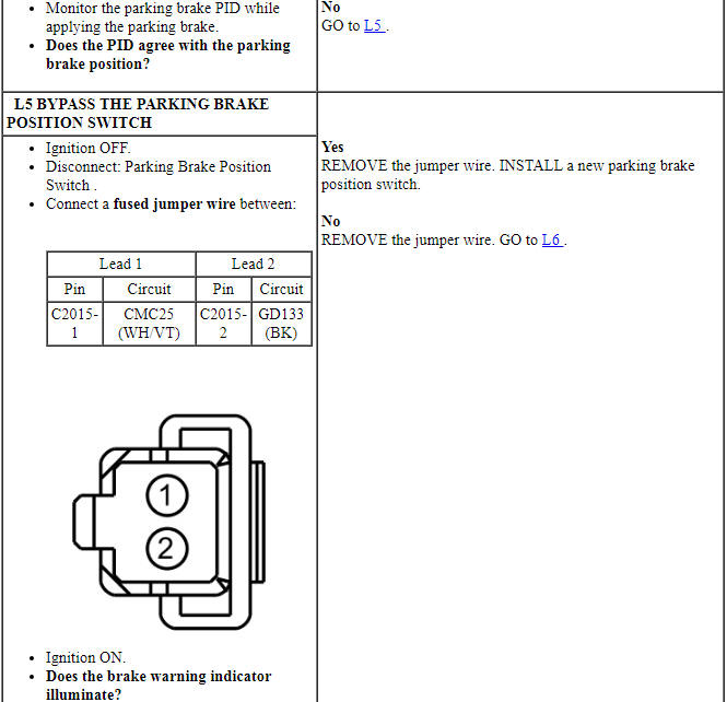
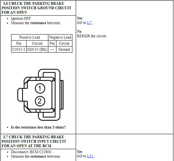
Pinpoint Test L: The Brake Warning Indicator is Never On
Diagnostic Overview
Diagnostics in this manual assume a certain skill level and knowledge of Ford-specific diagnostic practices. Refer to Diagnostic Methods in Section 100-00 for information about these practices.
Refer to Wiring Diagrams Cell 60, Instrument Cluster for schematic and connector information.
Normal Operation and Fault Conditions
REFER to Brake Warning Indicator, Parking Brake Position Switch and Brake Fluid Level Switch in Instrument Panel Cluster (IPC).
-
Possible Sources
- Wiring, terminals or connectors
- Brake fluid level switch
- Parking brake position switch
- BCM
- IPC
Visual Inspection and Diagnostic Pre-checks
Inspect the brake fluid level switch for signs of any external damage. Inspect the brake fluid level switch wiring for signs of a pinched harness causing the circuits to short together.
PINPOINT TEST L: THE BRAKE WARNING INDICATOR IS NEVER ON
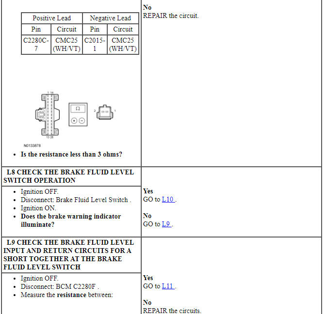
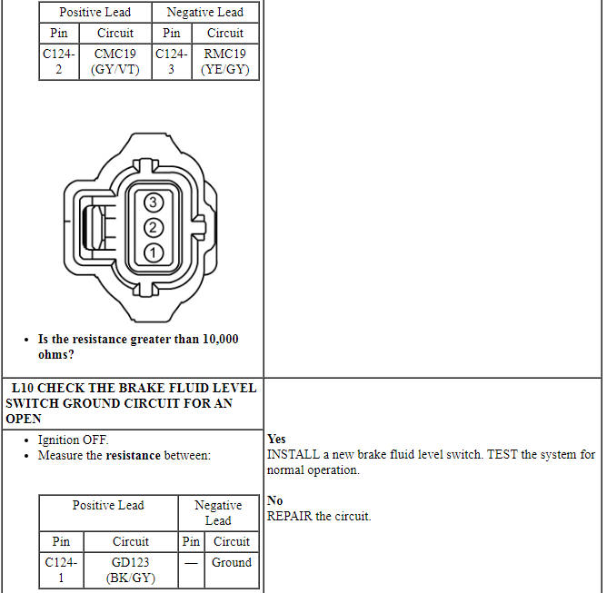
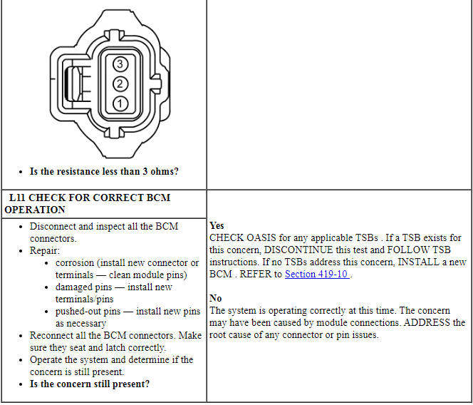
Pinpoint Test M: The Brake Warning Indicator is Always On
Diagnostic Overview
Diagnostics in this manual assume a certain skill level and knowledge of Ford-specific diagnostic practices. Refer to Diagnostic Methods in Section 100-00 for information about these practices.
Refer to Wiring Diagrams Cell 60, Instrument Cluster for schematic and connector information.
Normal Operation and Fault Conditions
REFER to Brake Warning Indicator, Parking Brake Position Switch and Brake Fluid Level Switch in Instrument Panel Cluster (IPC).
NOTE: Both the ABS warning indicator and the brake warning indicator illuminate if the input to illuminate the brake warning indicator is received from the ABS module.
NOTE: If DTC U0140:00 sets in the IPC, other symptoms can also be present such as TPMS, instrument panel backlighting, and door ajar indication. If DTC U0121:00 sets, other symptoms can also be present such as ABS warning indicator and traction control or traction control off indicators always on.
If the brake warning indicator request or brake (red) warning indicator request messages are missing for less than 5 seconds, the IPC defaults the brake warning indicator to its last state (on or off) based upon the last known good message received.
If the brake warning indicator request message is missing for more than 5 seconds, the IPC sets DTC U0140:00 and defaults the brake warning indicator on. If the IPC does not receive the brake (red) warning indicator request message from the ABS module for more than 5 seconds, the IPC sets DTC U0121:00 and defaults the ABS warning indicator on.
BCM DTC Fault Trigger Conditions

-
Possible Sources
- Wiring, terminals or connectors
- Brake fluid level switch
- Parking brake position switch
- ABS concern
- BCM
- IPC
Visual Inspection and Diagnostic Pre-checks
Inspect the:
- base brake system and the parking brake system for correct operation.
- brake fluid level switch connector connection and check for signs of connector terminal damage, corrosion or pushed-out pins.
- brake fluid level switch wiring for signs of a cut or opened circuit.
- brake fluid level switch for signs of any external damage.
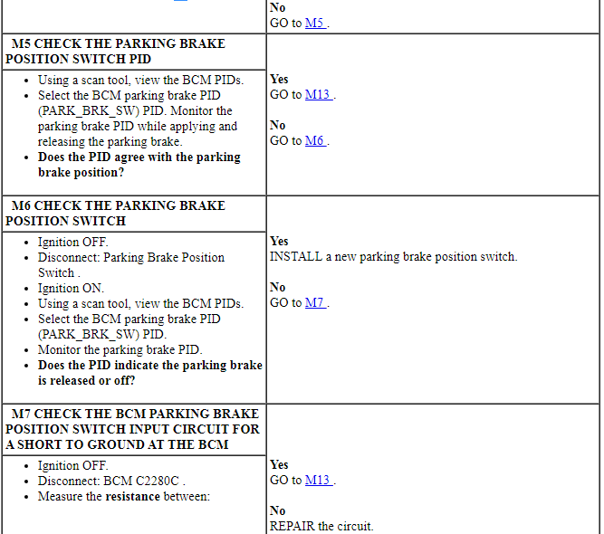
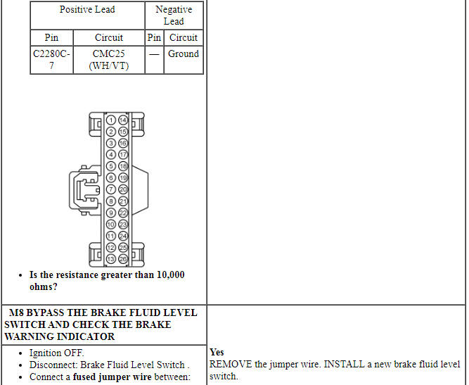
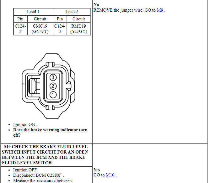
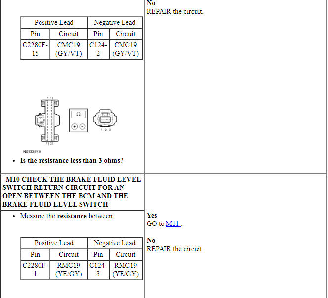
PINPOINT TEST M: THE BRAKE WARNING INDICATOR IS ALWAYS ON
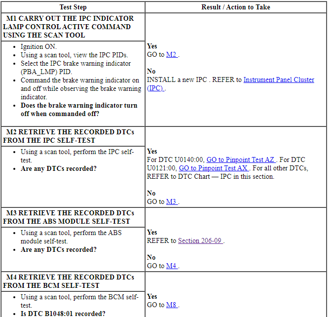
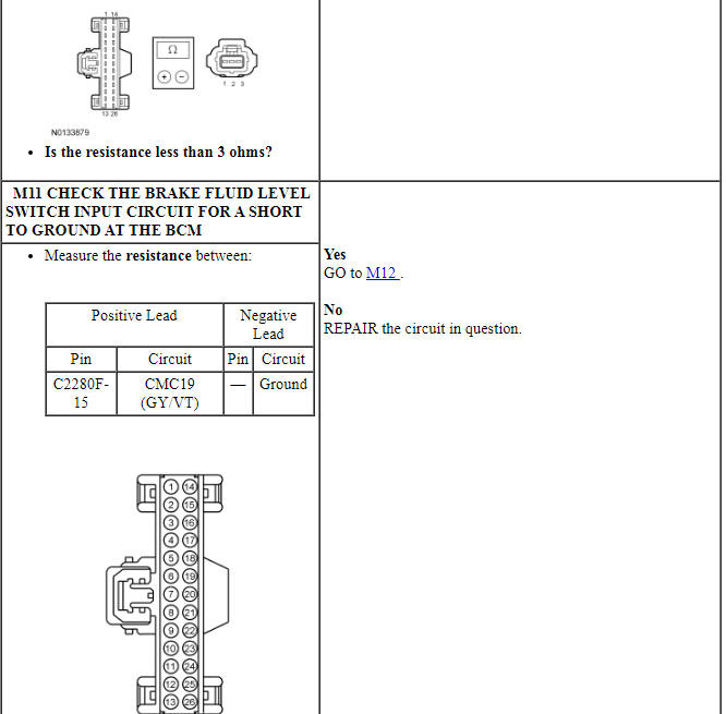
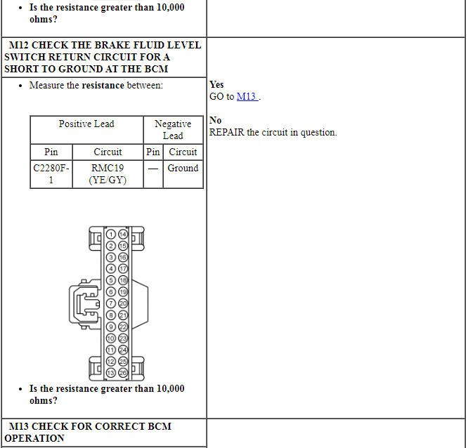
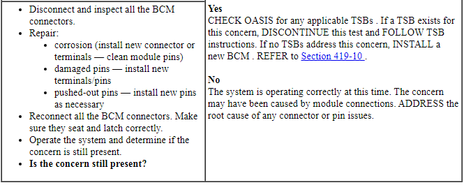
Pinpoint Test N: The ABS Warning Indicator Is Never-Always On
Diagnostic Overview
Diagnostics in this manual assume a certain skill level and knowledge of Ford-specific diagnostic practices. Refer to Diagnostic Methods in Section 100-00 for information about these practices.
Normal Operation and Fault Conditions
REFER to ABS Warning Indicator in Instrument Panel Cluster (IPC).
-
Possible Sources
- ABS concern
- ABS module
- IPC
PINPOINT TEST N: THE ABS WARNING INDICATOR IS NEVER-ALWAYS ON
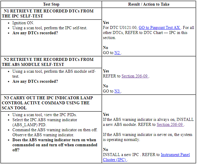
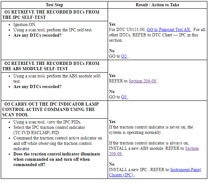
Pinpoint Test O: The Stability-Traction Control Indicator (Sliding Car Icon) Is Never-Always On
Diagnostic Overview
Diagnostics in this manual assume a certain skill level and knowledge of Ford-specific diagnostic practices. Refer to Diagnostic Methods in Section 100-00 for information about these practices.
Normal Operation and Fault Conditions
REFER to Stability-Traction Control Indicator (Sliding Car Icon) in Instrument Panel Cluster (IPC).
If the traction control indicator request message is invalid for less than 5 seconds or if the IPC does not receive the traction control message for less than 5 seconds, the IPC defaults the stability-traction control indicator (sliding car icon) to the last indication mode (on/off) based upon the last known good message. If the traction control indicator request message is missing for 5 seconds or longer, the IPC sets DTC U0121:00 in continuous memory and defaults the stability-traction control indicator (sliding car icon) on.
-
Possible Sources
- Stability-traction control system concern
- ABS module
- IPC
PINPOINT TEST O: THE STABILITY-TRACTION CONTROL INDICATOR (SLIDING CAR ICON) IS NEVER-ALWAYS ON
Pinpoint Test P: The Stability-Traction Control Disabled Indicator (Sliding Car OFF Icon) Is Never-Always On
Diagnostic Overview
Diagnostics in this manual assume a certain skill level and knowledge of Ford-specific diagnostic practices. Refer to Diagnostic Methods in Section 100-00 for information about these practices.
Normal Operation and Fault Conditions
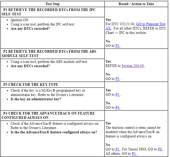
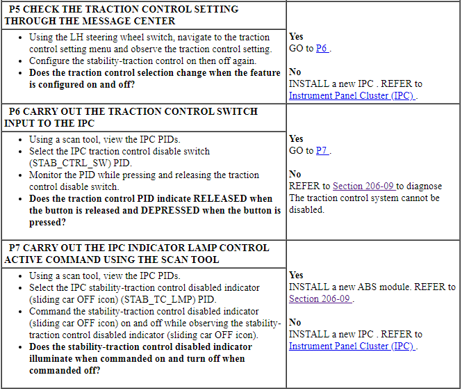
REFER to Stability-Traction Control Disabled Indicator (Sliding Car OFF Icon) in Instrument Panel Cluster (IPC).
NOTE: When a MyKey programmed key is in use and the AdvanceTrac on feature is configured always on, the traction control system cannot be disabled and the traction control indicator does not turn on when the traction control disable button is pressed. The traction control indicator still functions normally to indicate a traction control system fault and a traction control active event.
If the traction control disabled (OFF) indicator request message is missing for less than 5 seconds, the stability-traction control disabled indicator (sliding car OFF icon) remains in the last indication state (on or off) based upon the last known good message received. If the traction control disabled (OFF) indicator request message is missing for 5 seconds or longer, the IPC sets DTC U0121:00 in continuous memory and defaults the stability-traction control disabled indicator (sliding car OFF icon) off.
-
Possible Sources
- MyKey programmed key in use
- Stability-traction control system concern
- Stability-traction control system cannot be disabled
- ABS module
- IPC
PINPOINT TEST P: THE TRACTION CONTROL DISABLED INDICATOR (SLIDING CAR OFF ICON) IS NEVER-ALWAYS ON
Pinpoint Test Q: The Safety Belt Warning Indicator Is Never-Always On
Diagnostic Overview
Diagnostics in this manual assume a certain skill level and knowledge of Ford-specific diagnostic practices. Refer to Diagnostic Methods in Section 100-00 for information about these practices.
Normal Operation and Fault Conditions
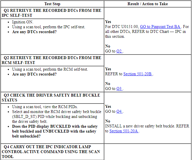
REFER to Safety Belt Warning Indicator in Instrument Panel Cluster (IPC).
If the safety belt indicator request message is missing or invalid for less than 5 seconds, the IPC defaults the safety belt warning indicator to its last state (on or off) based upon the last known good message received. If the IPC does not receive the safety belt indicator request message from the RCM or the message is deemed invalid by the IPC for 5 seconds or longer, the IPC sets DTC U0151:00 and defaults the safety belt warning indicator off.
-
Possible Sources
- Safety belt buckle concern
- RCM
- IPC
PINPOINT TEST Q: THE SAFETY BELT WARNING INDICATOR IS NEVER-ALWAYS ON

Pinpoint Test R: The Air Bag Warning Indicator Is Never-Always On
Diagnostic Overview
Diagnostics in this manual assume a certain skill level and knowledge of Ford-specific diagnostic practices. Refer to Diagnostic Methods in Section 100-00 for information about these practices.
Normal Operation and Fault Conditions
REFER to Air Bag Warning Indicator in Instrument Panel Cluster (IPC).
If the air bag indicator lamp request message is missing for less than 5 seconds, the IPC defaults the air bag warning indicator to its last state (on or off) based upon the last known good message received. If the air bag indicator lamp request message is missing or is deemed invalid for 5 seconds or longer, the IPC sets DTC U0151:00 in continuous memory and defaults the air bag warning indicator on.
-
Possible Sources
- SRS concern
- RCM
- IPC
PINPOINT TEST R: THE AIR BAG WARNING INDICATOR IS NEVER-ALWAYS ON
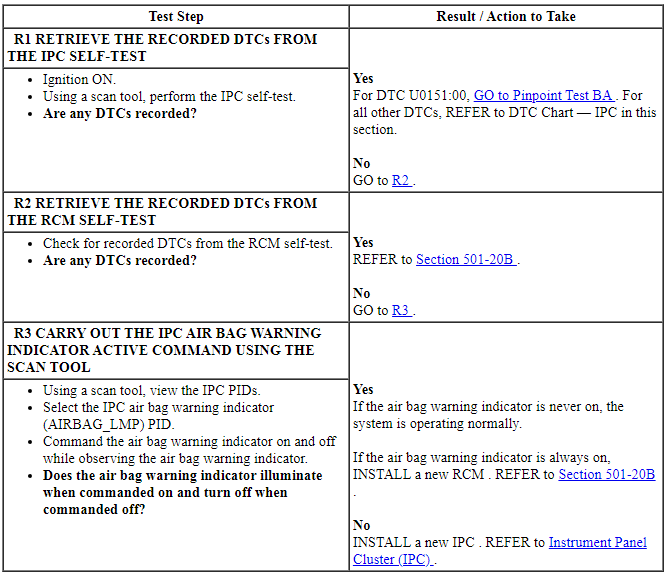
Pinpoint Test S: The LH-RH Turn, Fog Lamp Or High Beam Indicator Is Never-Always On
Diagnostic Overview
Diagnostics in this manual assume a certain skill level and knowledge of Ford-specific diagnostic practices. Refer to Diagnostic Methods in Section 100-00 for information about these practices.
Normal Operation and Fault Conditions
REFER to LH-RH Turn Signal, Fog Lamp or High Beam Indicator in Instrument Panel Cluster (IPC).
If the turn indicator command, headlamp high beam indicator request or fog lamp indicator request message is missing for less than 2 seconds, the IPC defaults the turn signals, high beam or fog lamp indicator to its last state (on or off) based upon the last known good message received. If the turn indicator command, headlamp high beam indicator request or fog lamp indicator request message is missing for 2 seconds or longer, the IPC sets DTC U0140:00 in continuous memory and defaults the turn signals, high beam or fog lamp indicator off.
-
Possible Sources
- Turn signal concern
- High beam concern
- Fog lamp concern
- BCM
- IPC
PINPOINT TEST S: THE LH-RH TURN, FOG LAMP OR HIGH BEAM INDICATOR IS NEVER-ALWAYS ON
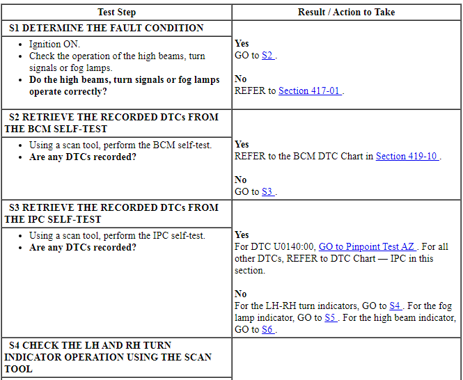
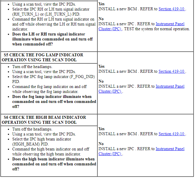
Pinpoint Test T: The Tire Pressure Monitoring System (TPMS) Warning Indicator Is Never-Always On
Diagnostic Overview
Diagnostics in this manual assume a certain skill level and knowledge of Ford-specific diagnostic practices. Refer to Diagnostic Methods in Section 100-00 for information about these practices.
Normal Operation and Fault Conditions
REFER to Tire Pressure Monitoring System (TPMS) Warning Indicator in Instrument Panel Cluster (IPC).
NOTE: If DTC U0140:00 sets in the IPC, other symptoms can also be present such as an inoperative high beam indicator, RH/LH turn indicators, instrument panel backlighting, and door ajar indication.
If the tire pressure status message is missing for 5 seconds or less, the TPMS warning indicator remains in its last indication state (on or off) based on the last known good message received. If the tire pressure status message is missing for more than 5 seconds, the IPC sets DTC U0140:00 and flashes the TPMS warning indicator for approximately 75 seconds then illuminates the TPMS warning indicator.
-
Possible Sources
- Low tire pressure
- TPMS concern
- IPC
PINPOINT TEST T: THE TPMS WARNING INDICATOR IS NEVER-ALWAYS ON
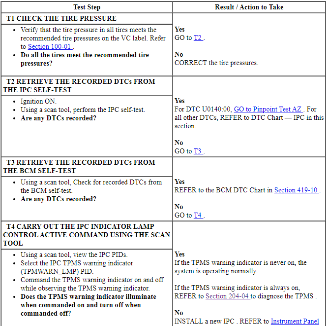

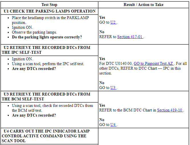
Pinpoint Test U: The Lights On Indicator Is Never-Always On
Diagnostic Overview
Diagnostics in this manual assume a certain skill level and knowledge of Ford-specific diagnostic practices. Refer to Diagnostic Methods in Section 100-00 for information about these practices.
Normal Operation and Fault Conditions
REFER to Lights On Indicator in Instrument Panel Cluster (IPC).
NOTE: If DTC U0140:00 sets in the IPC, other symptoms can also be present such as an inoperative high beam indicator, RH/LH turn indicators, instrument panel backlighting, and door ajar indication.
If the parklamp status message is missing for less than 5 seconds, the IPC defaults the lights on indicator to its last state (on or off) based upon the last known good message received. If the park lamp status message is missing for 5 seconds or longer, the IPC sets DTC U0140:00 in continuous memory and defaults the lights on indicator off.
-
Possible Sources
- Exterior lighting concern
- BCM
- IPC
PINPOINT TEST U: THE LIGHTS ON INDICATOR IS NEVER-ALWAYS ON

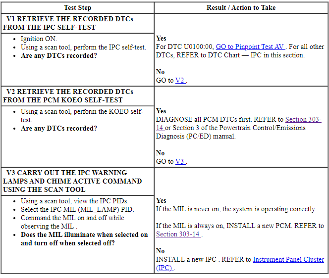
Pinpoint Test V: The MIL Is Never-Always On
Diagnostic Overview
Diagnostics in this manual assume a certain skill level and knowledge of Ford-specific diagnostic practices. Refer to Diagnostic Methods in Section 100-00 for information about these practices.
Normal Operation and Fault Conditions
REFER to Malfunction Indicator Lamp (MIL) in Instrument Panel Cluster (IPC).
NOTE: If DTC U0100:00 sets in the IPC, other observable symptoms can be an inoperative speedometer, tachometer or odometer.
If the engine MIL request message is missing or invalid for less than 5 seconds, the IPC defaults the MIL to its last state (on or off) based upon the last known good message received. If the engine MIL request message is missing for 5 seconds or longer, the IPC sets DTC U0100:00 in continuous memory and defaults the MIL on.
-
Possible Sources
- Powertrain concern
- PCM
- IPC
PINPOINT TEST V: THE MIL IS NEVER-ALWAYS ON
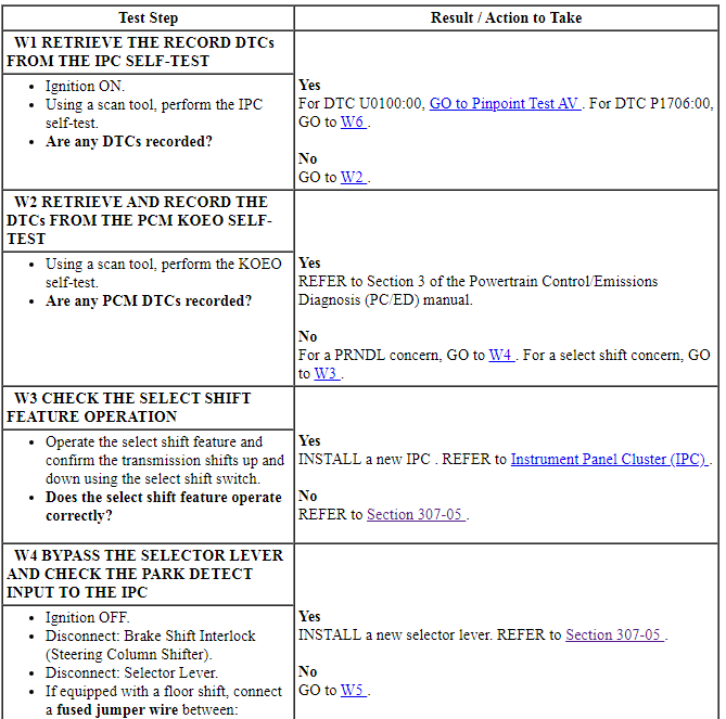
Pinpoint Test W: The PRNDL/Select Shift Indicator Is Never On Or Never Displays P
Diagnostic Overview
Diagnostics in this manual assume a certain skill level and knowledge of Ford-specific diagnostic practices. Refer to Diagnostic Methods in Section 100-00 for information about these practices.
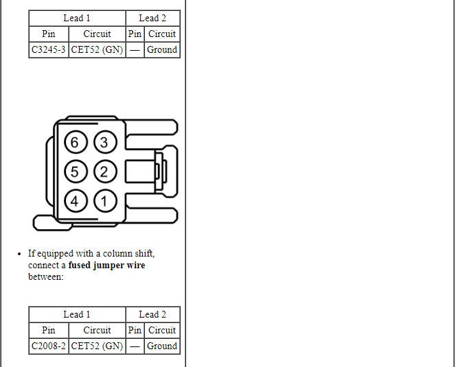
Refer to Wiring Diagrams Cell 60, Instrument Cluster for schematic and connector information.
Normal Operation and Fault Conditions
REFER to PRNDL Indicator in Instrument Panel Cluster (IPC).
NOTE: If DTC U0100:00 sets in the IPC, other observable symptoms can be an inoperative speedometer, tachometer or odometer.
If the PRNDL information is missing from the PCM, the IPC sets DTC U0100:00.
IPC DTC Fault Trigger Conditions

-
Possible Sources
- Wiring, terminals or connectors
- Park detect switch (part of the selector lever)
- Transmission concern
- PCM
- IPC
PINPOINT TEST W: THE PRNDL/SELECT SHIFT INDICATOR IS NEVER ON OR NEVER DISPLAYS P
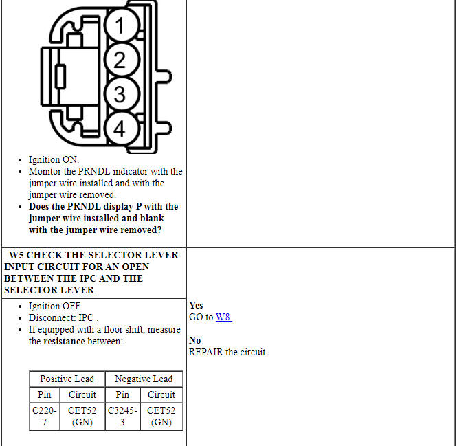
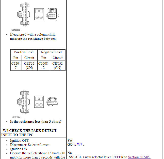
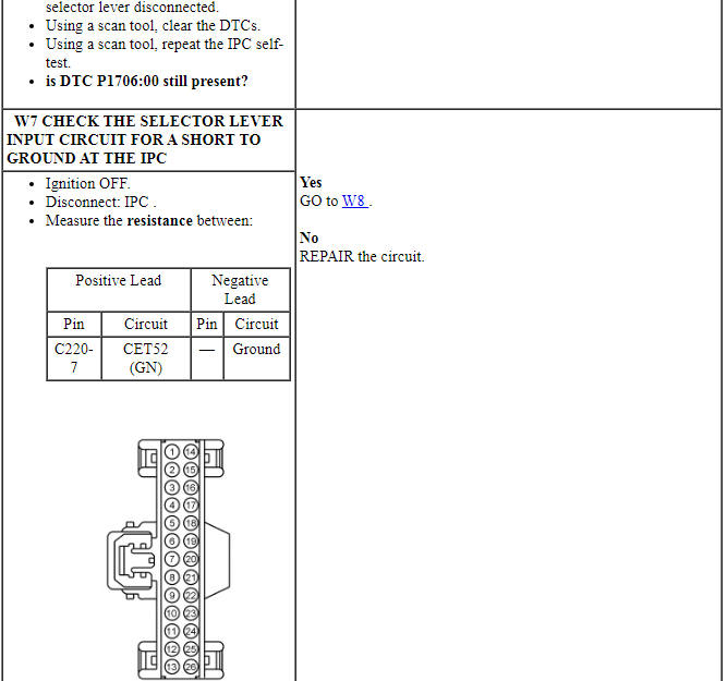
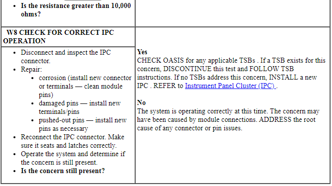
Pinpoint Test X: The Message Center Is Not Operating Correctly
Diagnostic Overview
Diagnostics in this manual assume a certain skill level and knowledge of Ford-specific diagnostic practices. Refer to Diagnostic Methods in Section 100-00 for information about these practices.
Refer to Wiring Diagrams Cell 60, Instrument Cluster for schematic and connector information.
Normal Operation and Fault Conditions
REFER to Message Center Overview in Information And Message Center.
REFER to the Message Center Component Description/Steering Wheel Switch - Message Center in Information And Message Center.
SCCM DTC Fault Trigger Conditions

-
Possible Sources
- Wiring, terminals or connectors
- Clockspring
- Message center switch (part of the LH steering wheel switch)
- SCCM
- IPC
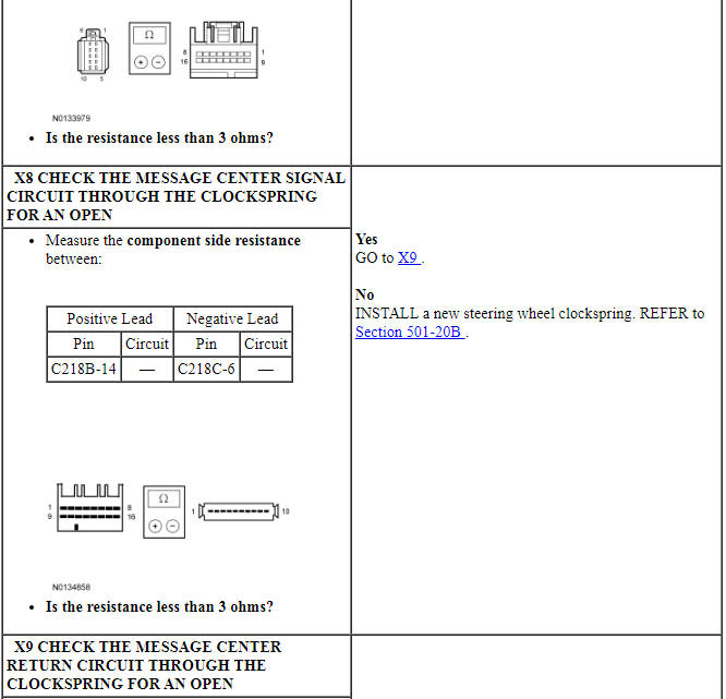
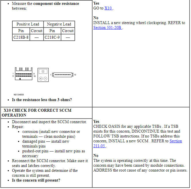
PINPOINT TEST X: THE MESSAGE CENTER IS NOT OPERATING CORRECTLY
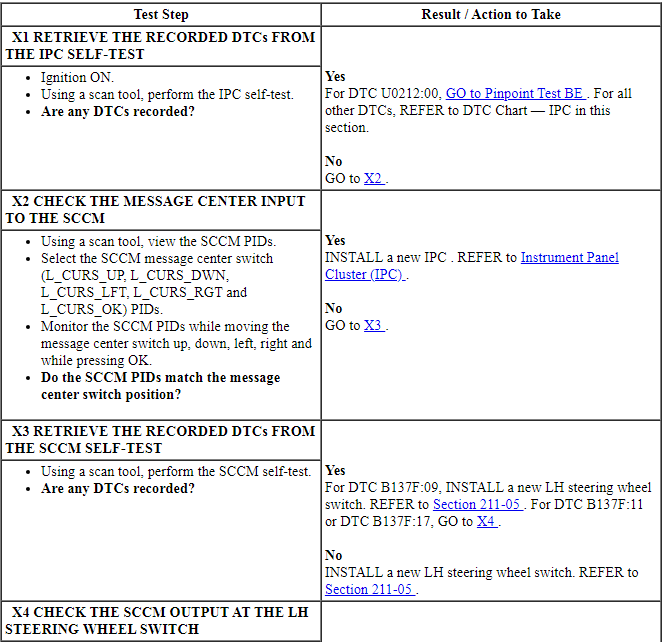
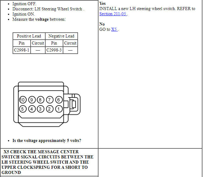
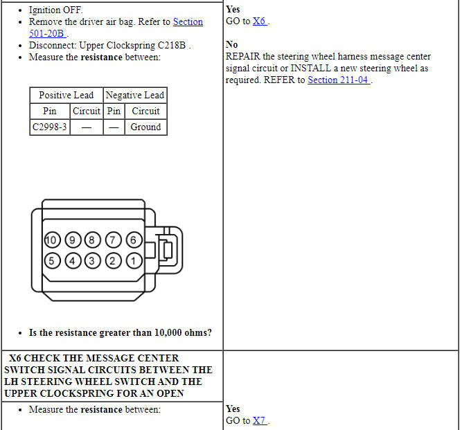
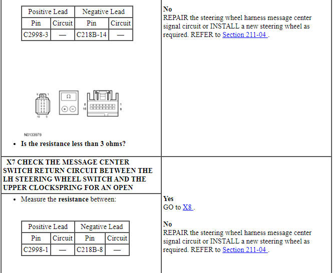
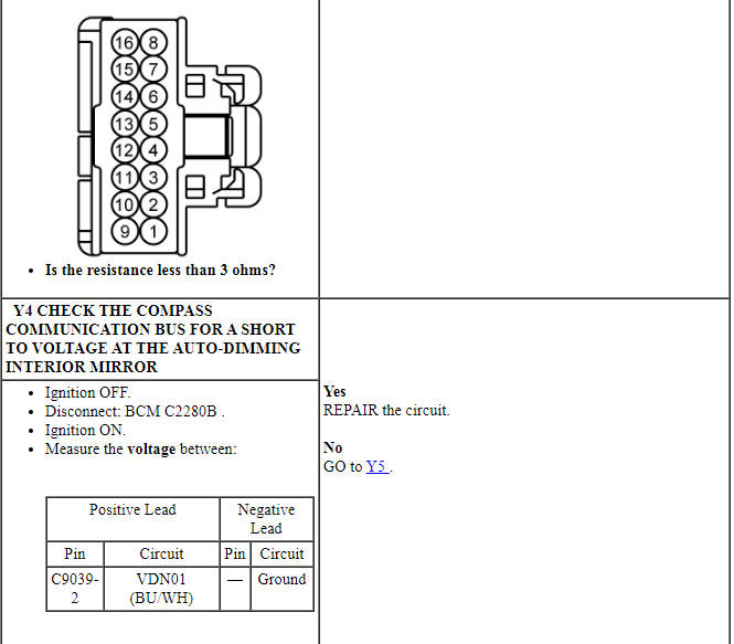
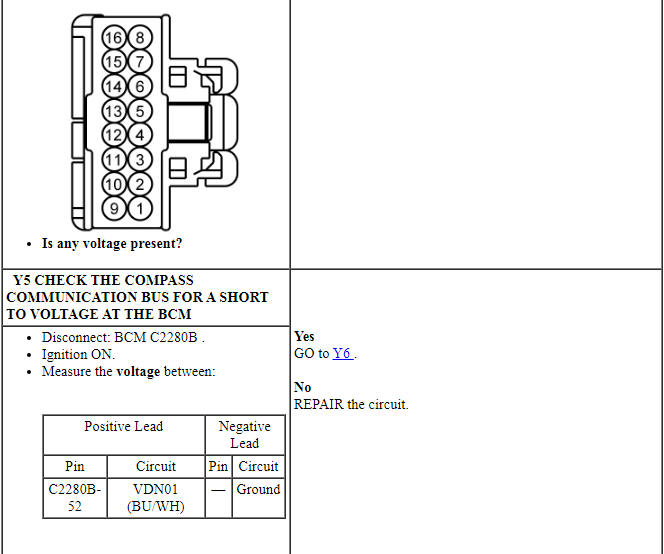
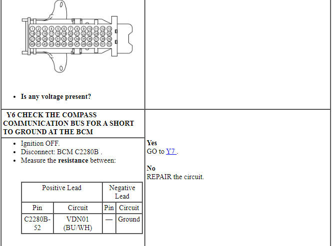
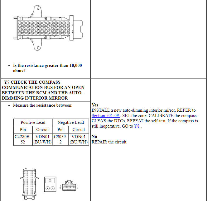
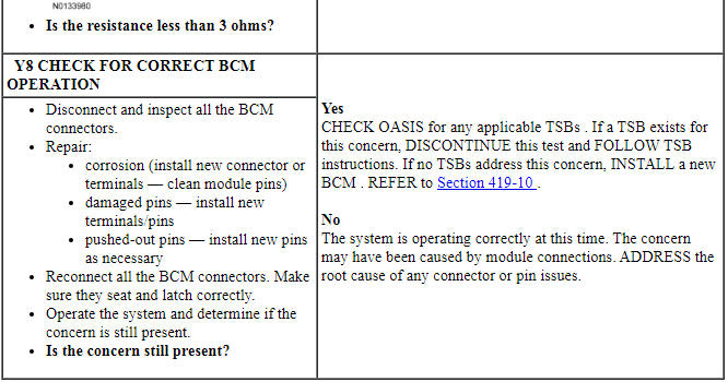
Pinpoint Test Y: The Compass Display Is Inoperative (Except SYNC)
NOTE: This pinpoint test is only applicable to vehicles without SYNC. For all other vehicles, Refer to the appropriate section in Group 415 for the procedure. to diagnose the navigation system.
Diagnostic Overview
Diagnostics in this manual assume a certain skill level and knowledge of Ford-specific diagnostic practices. Refer to Diagnostic Methods in Section 100-00 for information about these practices.
Refer to Wiring Diagrams Cell 60, Instrument Cluster for schematic and connector information.
Normal Operation and Fault Conditions
REFER to Compass Display - Except SYNC and Compass Module - SYNC component descriptions in Information And Message Center.
IPC DTC Fault Trigger Conditions

-
Possible Sources
- Fuse
- Wiring, terminals of connectors
- Auto-dimming interior mirror
- BCM
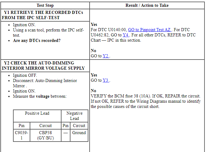
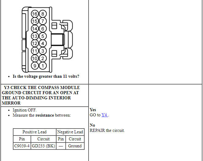
PINPOINT TEST Y: THE COMPASS IS INOPERATIVE (EXCEPT SYNC)
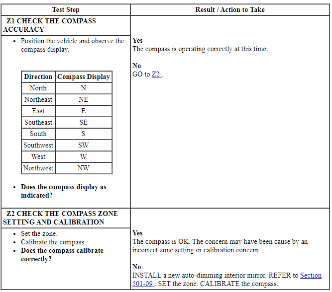
Pinpoint Test Z: The Compass Display Is Inaccurate (Except SYNC)
NOTE: This pinpoint test is only applicable to vehicles without SYNC. For all other vehicles, refer to Refer to the appropriate section in Group 415 for the procedure. to diagnose the navigation system.
Diagnostic Overview
Diagnostics in this manual assume a certain skill level and knowledge of Ford-specific diagnostic practices. Refer to Diagnostic Methods in Section 100-00 for information about these practices.
Normal Operation and Fault Conditions
REFER to Compass Display - Except SYNC and Compass Module - SYNC component descriptions in Information And Message Center.
-
Possible Sources
- Compass zone setting
- Compass calibration
- Auto-dimming interior mirror
PINPOINT TEST Z: THE COMPASS IS INACCURATE (EXCEPT SYNC)
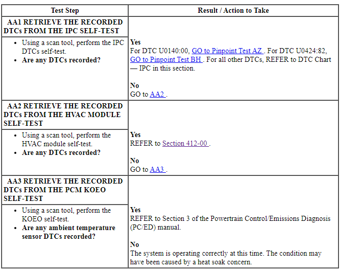
Pinpoint Test AA: The Outside Air Temperature Display Is Inoperative or Incorrect
Diagnostic Overview
Diagnostics in this manual assume a certain skill level and knowledge of Ford-specific diagnostic practices. Refer to Diagnostic Methods in Section 100-00 for information about these practices.
Normal Operation and Fault Conditions
REFER to Outside Air Temperature Display in Information And Message Center.
-
Possible Sources
- Communication concern
- AAT input concern to the PCM
- PCM
PINPOINT TEST AA: THE OUTSIDE AIR TEMPERATURE DISPLAY IS INOPERATIVE OR INCORRECT
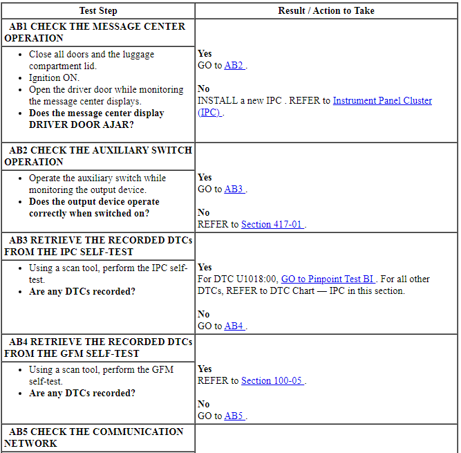
Pinpoint Test AB: The Auxiliary Switch Menu Display Is Inoperative (Police Package)
Diagnostic Overview
Diagnostics in this manual assume a certain skill level and knowledge of Ford-specific diagnostic practices. Refer to Diagnostic Methods in Section 100-00 for information about these practices.
Normal Operation and Fault Conditions
REFER to Auxiliary Switch Menu Display - Police Package in Information And Message Center.
-
Possible Sources
- Auxiliary switch input to the GFM concern
- Generic function module
- IPC
PINPOINT TEST AB: THE AUXILIARY SWITCH MENU DISPLAY IS INOPERATIVE (POLICE PACKAGE)

Pinpoint Test AC: The Adaptive Cruise Control/Cruise Control Message Center Indicator Is Never On
Diagnostic Overview
Diagnostics in this manual assume a certain skill level and knowledge of Ford-specific diagnostic practices. Refer to Diagnostic Methods in Section 100-00 for information about these practices.
Normal Operation and Fault Conditions
REFER to Cruise Control Message Center Indicator in Information And Message Center.
-
Possible Sources
- Cruise control concern
- Communication concern
- PCM
- IPC
PINPOINT TEST AC: THE ADAPTIVE CRUISE CONTROL/CRUISE CONTROL MESSAGE CENTER INDICATOR IS NEVER ON
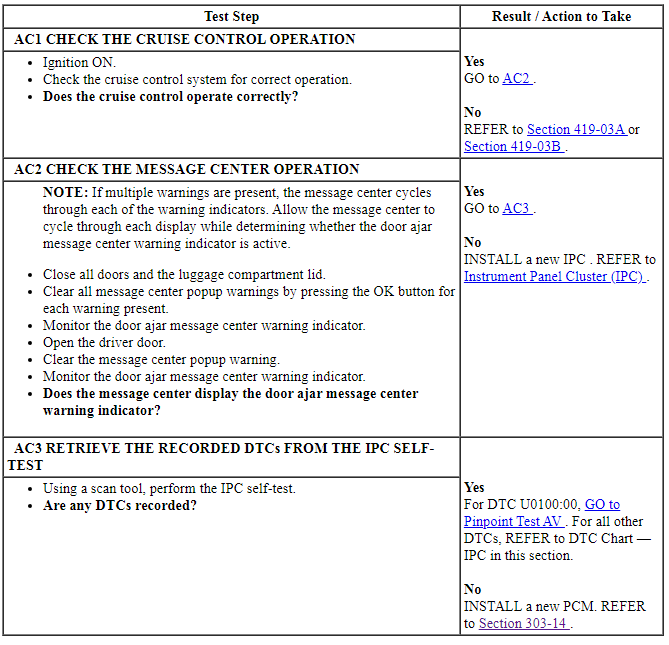
Pinpoint Test AD: The Charging System Message Center Warning Indicator Is Never-Always On
Diagnostic Overview
Diagnostics in this manual assume a certain skill level and knowledge of Ford-specific diagnostic practices. Refer to Diagnostic Methods in Section 100-00 for information about these practices.
Normal Operation and Fault Conditions
REFER to Charging System Message Center Warning Indicator in Information And Message Center.
-
Possible Sources
- Charging system concern
- PCM
- BCM
- IPC
PINPOINT TEST AD: THE CHARGING SYSTEM MESSAGE CENTER WARNING INDICATOR IS NEVER-ALWAYS ON
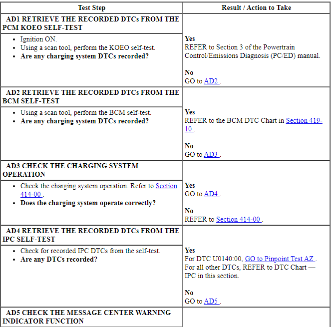
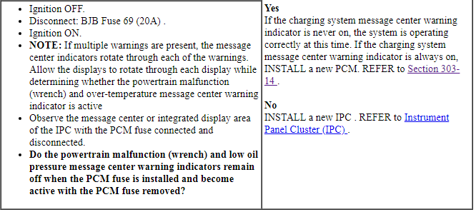
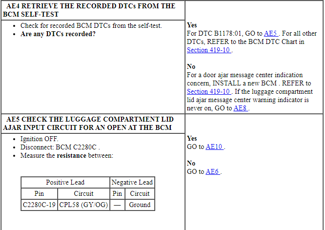
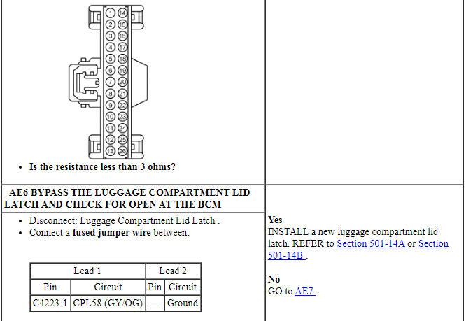
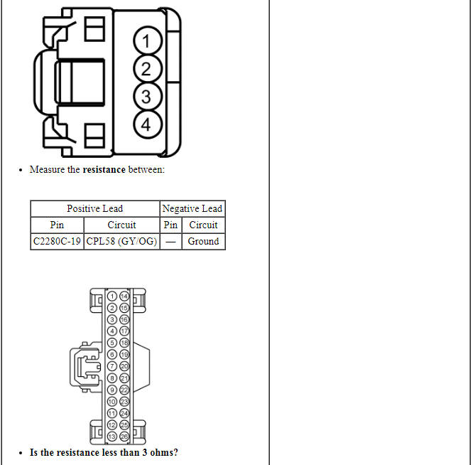
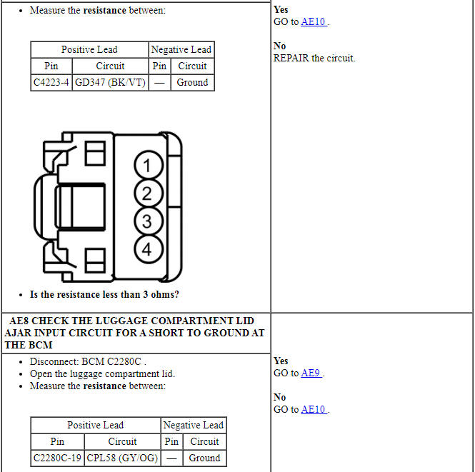
Pinpoint Test AE: The Door-Luggage Compartment Lid Ajar Message Center Warning Indicator Is Never-Always On
Diagnostic Overview
Diagnostics in this manual assume a certain skill level and knowledge of Ford-specific diagnostic practices. Refer to Diagnostic Methods in Section 100-00 for information about these practices.
Normal Operation and Fault Conditions
REFER to Door-Luggage Compartment Lid Ajar Message Center Indicator in Information And Message Center.
NOTE: If DTC U0140:00 sets in the IPC, other symptoms can also be present such as inoperative high beam indicator, turn indicators or the TPMS warning indicator can be always on.
If the driver door, passenger door, driver rear door, passenger rear door or luggage compartment lid ajar status message is missing for less than 5 seconds, the door ajar indication remains in its last indication state (on or off) based upon the last known good message received. If the driver door, passenger door, driver rear door, passenger rear door or luggage compartment lid ajar status message is missing for 5 seconds or longer, the IPC sets DTC U0140:00 and defaults the door-luggage compartment lid ajar message center warning indicator on or active.
BCM DTC Fault Trigger Conditions

-
Possible Sources
- Wiring, terminals or connectors
- Interior lighting concern
- Luggage compartment lid ajar switch (part of the luggage compartment lid latch)
- BCM
- IPC
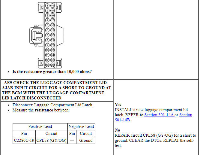
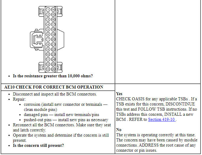
PINPOINT TEST AE: THE DOOR-LUGGAGE COMPARTMENT LID AJAR MESSAGE CENTER WARNING INDICATOR IS NEVER-ALWAYS ON
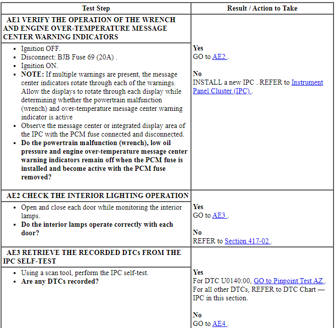
Pinpoint Test AF: The Grade Assist Message Center Indicator Is Never-Always On
Diagnostic Overview
Diagnostics in this manual assume a certain skill level and knowledge of Ford-specific diagnostic practices. Refer to Diagnostic Methods in Section 100-00 for information about these practices.
Normal Operation and Fault Conditions
REFER to Grade Assist Message Center Indicator in Information And Message Center.
NOTE: If DTC U0100:00 sets in the IPC, other observable symptoms can be an inoperative speedometer, tachometer or odometer.
If the transmission shift mode message is missing for less than 5 seconds, the grade assist message center indicator remains in the last indication mode (on or off) based upon the last known good message. If the transmission shift mode message is missing for 5 seconds or longer, the IPC sets DTC U0100:00 in continuous memory and defaults the grade assist message center indicator off.
-
Possible Sources
- Grade assist system concern
- Transmission concern
- PCM
- IPC
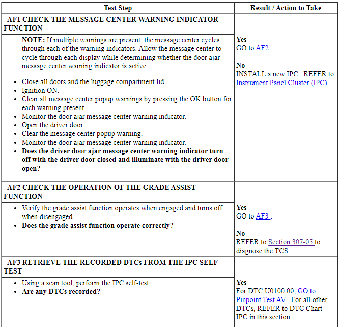
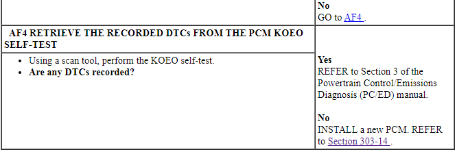
PINPOINT TEST AF: THE GRADE ASSIST MESSAGE CENTER INDICATOR IS NEVER-ALWAYS ON
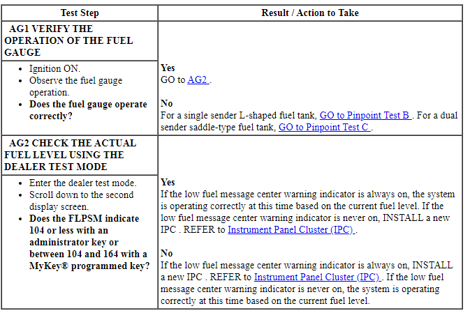
Pinpoint Test AG: The Low Fuel Message Center Warning Indicator Is Never-Always On
Diagnostic Overview
Diagnostics in this manual assume a certain skill level and knowledge of Ford-specific diagnostic practices. Refer to Diagnostic Methods in Section 100-00 for information about these practices.
Refer to Wiring Diagrams Cell 60, Instrument Cluster for schematic and connector information.
Normal Operation and Fault Conditions
REFER to Low Fuel Message Center Warning Indicator in Information And Message Center.
-
Possible Sources
- IPC
PINPOINT TEST AG: THE LOW FUEL MESSAGE CENTER WARNING INDICATOR IS NEVER-ALWAYS ON
Pinpoint Test AH: The Low Oil Pressure Message Center Warning Indicator Is Never-Always On
Diagnostic Overview
Diagnostics in this manual assume a certain skill level and knowledge of Ford-specific diagnostic practices. Refer to Diagnostic Methods in Section 100-00 for information about these practices.
Refer to Wiring Diagrams Cell 60, Instrument Cluster for schematic and connector information.
Normal Operation and Fault Conditions
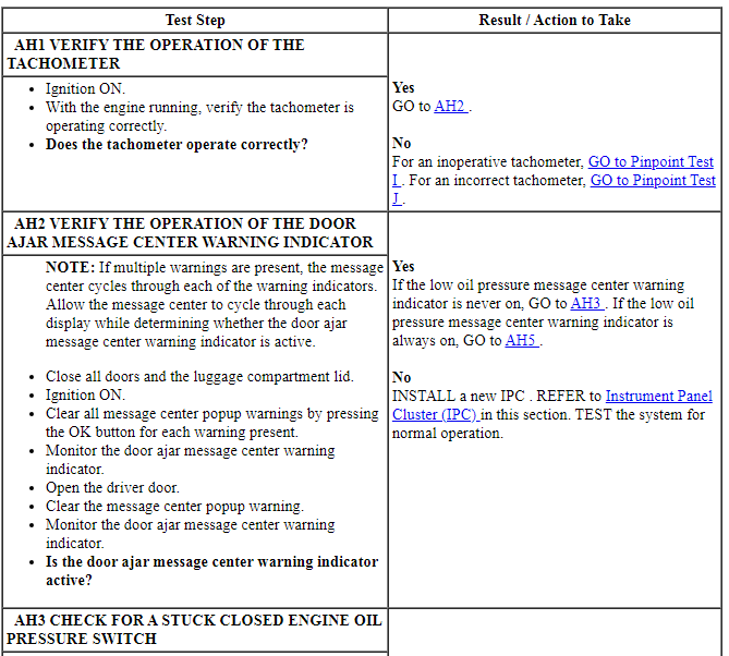
REFER to Low Oil Pressure Message Center Warning Indicator in Information And Message Center.
NOTE: If DTC U0100:00 sets in the IPC, other observable symptoms can be an inoperative speedometer, tachometer, temperature gauge or odometer.
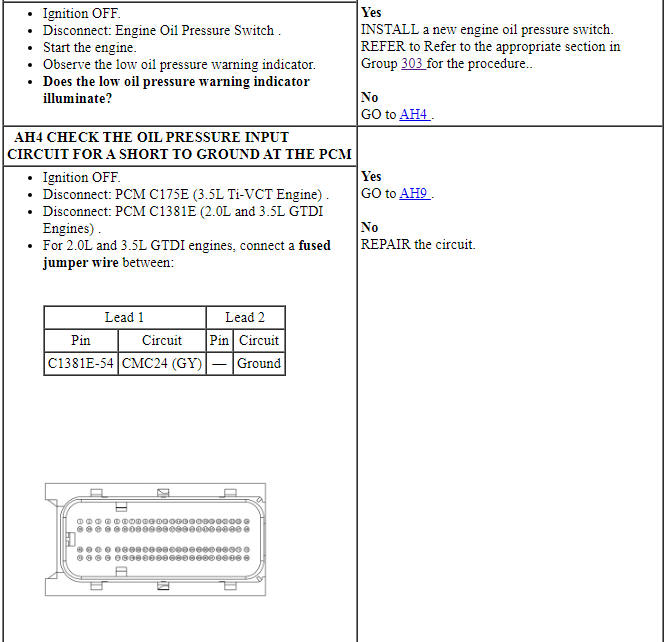
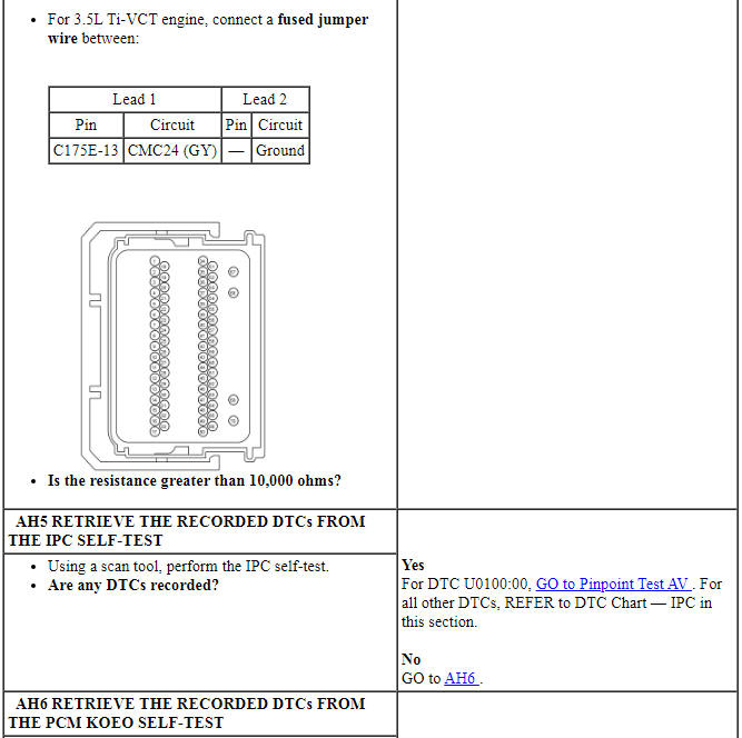
If the IPC fails to receive the oil pressure warning message from the PCM for less than 5 seconds, the IPC defaults the low oil pressure warning indicator to the last state (on or off), based upon the last known good oil pressure status message. If the IPC fails to receive the oil pressure warning message from the PCM for 5 seconds or longer, the IPC sets DTC U0100:00 in continuous memory and defaults the low oil pressure warning indicator on or active.
-
Possible Sources
- Wiring, terminals or connectors
- Tachometer concern
- Engine oil pressure switch
- Base engine oil pressure concern
- PCM
- IPC
Visual Inspection and Diagnostic Pre-checks
Inspect:
- the engine for noise that indicates a low engine oil pressure concern.
- the tachometer for correct operation.
- the engine oil pressure switch for signs of external damage.
- the engine oil pressure switch connector for signs of corrosion and inspect the harness for damage indicating a cut, open or circuit shorted to ground.
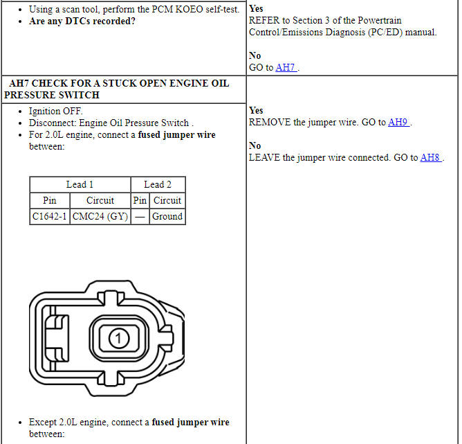
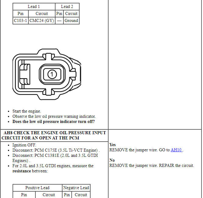
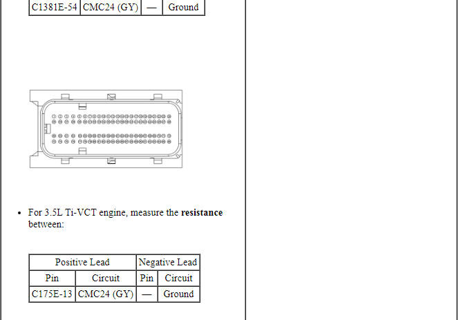
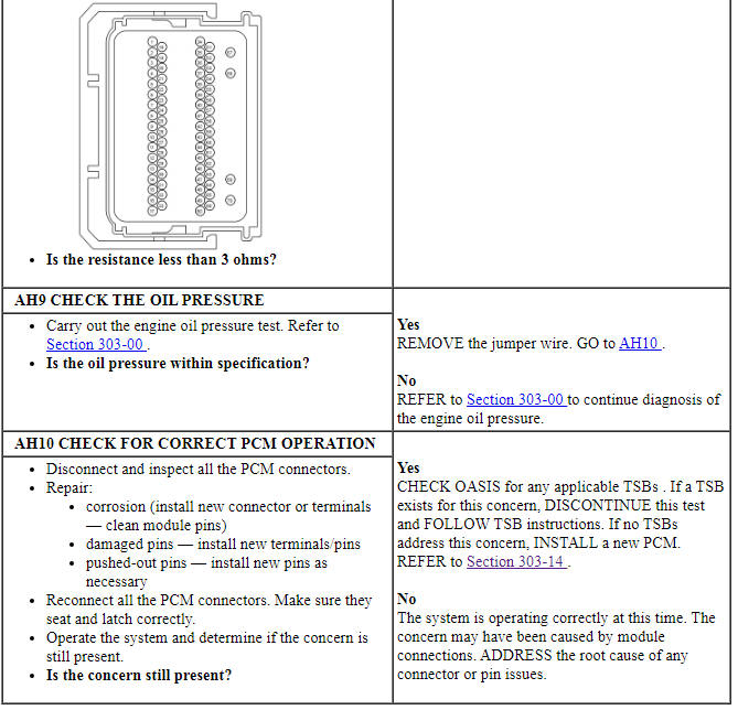
PINPOINT TEST AH: THE LOW OIL PRESSURE MESSAGE CENTER WARNING INDICATOR IS NEVER-ALWAYS ON
Pinpoint Test AI: The Low Washer Fluid Message Center Indicator Is Never-Always On
Diagnostic Overview
Diagnostics in this manual assume a certain skill level and knowledge of Ford-specific diagnostic practices. Refer to Diagnostic Methods in Section 100-00 for information about these practices.
Refer to Wiring Diagrams Cell 60, Instrument Cluster for schematic and connector information.
Normal Operation and Fault Conditions
REFER to Low Washer Fluid Message Center Indicator in Information And Message Center.
-
Possible Sources
- Wiring, terminals or connectors
- Washer fluid level switch
- IPC
Visual Inspection and Diagnostic Pre-checks
Verify the washer fluid reservoir is full and that the ignition has been cycled at least once prior to beginning the pinpoint test for an always on condition or that the washer fluid is or has been reported low for an never on condition.
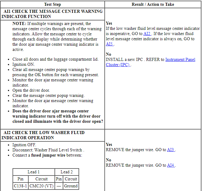
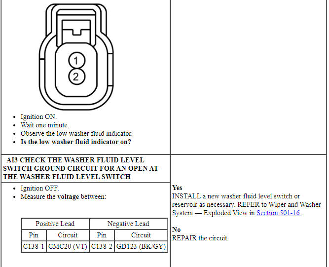
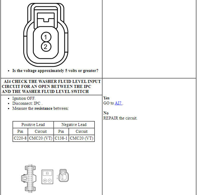
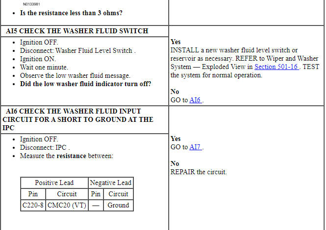
PINPOINT TEST AI: THE LOW WASHER FLUID LEVEL MESSAGE CENTER INDICATOR IS NEVER-ALWAYS ON
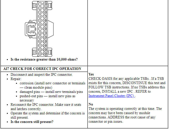
Pinpoint Test AJ: The Powertrain Malfunction (Wrench) Message Center Warning Indicator Is Never-Always On
Diagnostic Overview
Diagnostics in this manual assume a certain skill level and knowledge of Ford-specific diagnostic practices. Refer to Diagnostic Methods in Section 100-00 for information about these practices.
Normal Operation and Fault Conditions
REFER to Powertrain Malfunction (Wrench) Message Center Indicator in Information And Message Center.
If the engine service required, transmission malfunction indicator request or AWD lock status message is missing for less than 5 seconds, the powertrain malfunction (wrench) message center warning indicator remains in the last indication mode (on/off) based upon the last known good message. If the engine service required, transmission malfunction indicator request or AWD lock status message is missing for 5 seconds or longer, the IPC sets DTC U0100:00 and defaults the powertrain malfunction (wrench) message center warning indicator on.
-
Possible Sources
- ETC concern
- Transmission concern
- AWD concern
- IPC
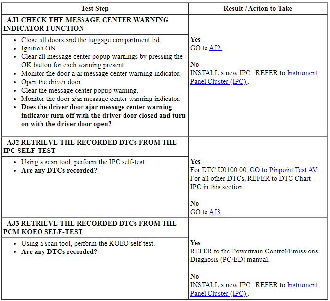
PINPOINT TEST AJ: THE POWERTRAIN MALFUNCTION (WRENCH) MESSAGE CENTER WARNING INDICATOR IS NEVER-ALWAYS ON
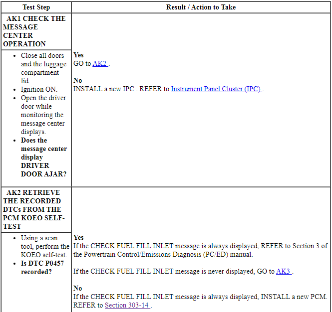
Pinpoint Test AK: The Check Fuel Fill Inlet Message Is Never or Always Displayed
Diagnostic Overview
Diagnostics in this manual assume a certain skill level and knowledge of Ford-specific diagnostic practices. Refer to Diagnostic Methods in Section 100-00 for information about these practices.
Normal Operation and Fault Conditions
REFER to Check Fuel Fill Inlet Message Display in Information And Message Center.
If the IPC does not receive the fuel inlet status from the PCM for 5 seconds, the IPC sets DTC U0100:00 in continuous memory and defaults the CHECK FUEL FILL INLET message off.
PCM DTC Fault Trigger Conditions

-
Possible Sources
- Evaporative emissions system concern
- PCM
- IPC
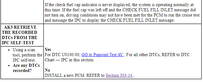
PINPOINT TEST AK: THE CHECK FUEL FILL INLET MESSAGE IS NEVER OR ALWAYS DISPLAYED
Pinpoint Test AL: The Shift To Park Message Is Never or Always Displayed ( IA Only)
Refer to Wiring Diagrams Cell 60, Instrument Cluster for schematic and connector information.
Diagnostic Overview
Diagnostics in this manual assume a certain skill level and knowledge of Ford-specific diagnostic practices. Refer to Diagnostic Methods in Section 100-00 for information about these practices.
Normal Operation and Fault Conditions
REFER to Shift To Park Message Display in Information And Message Center.
-
Possible Sources
- Communication concern
- BCM
- IPC
Visual Inspection and Diagnostic Pre-checks
Visually inspect the transmission range selector and make sure that the selector lever fully locks in the PARK (P) position and that there is not any binding of the transmission range selector.
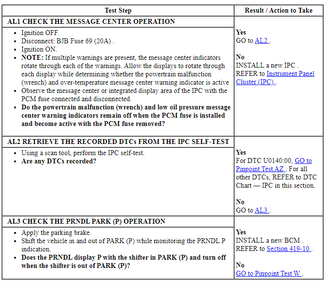
PINPOINT TEST AL: THE SHIFT TO PARK MESSAGE IS NEVER OR ALWAYS DISPLAYED ( IA ONLY)
Pinpoint Test AM: The Chime Always Sounds
Diagnostic Overview
Diagnostics in this manual assume a certain skill level and knowledge of Ford-specific diagnostic practices. Refer to Diagnostic Methods in Section 100-00 for information about these practices.
Refer to Wiring Diagrams Cell 60, Instrument Cluster for schematic and connector information.
Normal Operation and Fault Conditions
REFER to Key-In-Ignition Warning Chime and Headlamps On Warning Chime in Warning Chimes.
The chime can sound all the time as a result of a key-in-ignition warning chime concern or a headlamps on warning chime concern.
BCM DTC Fault Trigger Conditions

-
Possible Sources
- Wiring, terminals or connectors
- Exterior lighting concur
- Interior lighting concern
- Key-in-ignition switch (part of the ignition switch) (except IA )
- BCM
- IPC
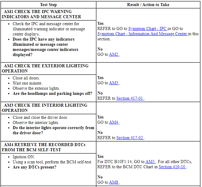
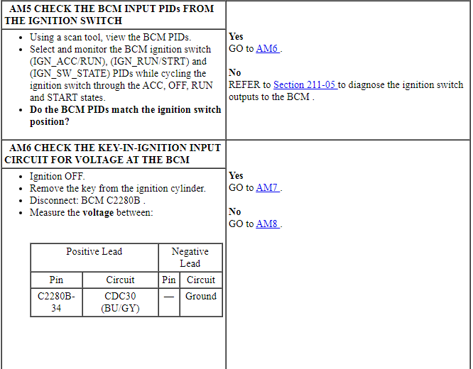
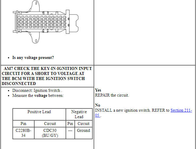
PINPOINT TEST AM: THE CHIME ALWAYS SOUNDS
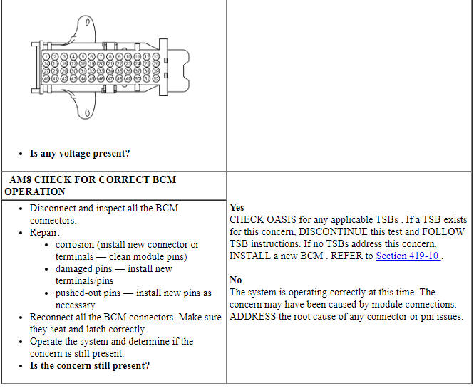
Pinpoint Test AN: The BLIS / CTA Warning Chime Is Inoperative
Diagnostic Overview
Diagnostics in this manual assume a certain skill level and knowledge of Ford-specific diagnostic practices. Refer to Diagnostic Methods in Section 100-00 for information about these practices.
Normal Operation and Fault Conditions
REFER to BLIS / CTA Warning Chime in Warning Chimes.
-
Possible Sources
- BLIS / CTA system concern
- IPC
PINPOINT TEST AN: THE BLIS / CTA WARNING CHIME IS INOPERATIVE
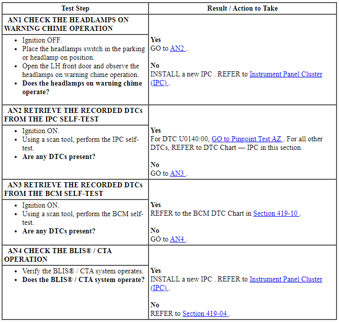
Pinpoint Test AO: The Headlamps On Warning Chime Is Inoperative
Diagnostic Overview
Diagnostics in this manual assume a certain skill level and knowledge of Ford-specific diagnostic practices. Refer to Diagnostic Methods in Section 100-00 for information about these practices.
Normal Operation and Fault Conditions
REFER to Headlamps On Warning Chime in Warning Chimes.
-
Possible Sources
- Door ajar indication concern
- Interior lighting concern
- BCM
- IPC
PINPOINT TEST AO: THE HEADLAMPS ON WARNING CHIME IS INOPERATIVE
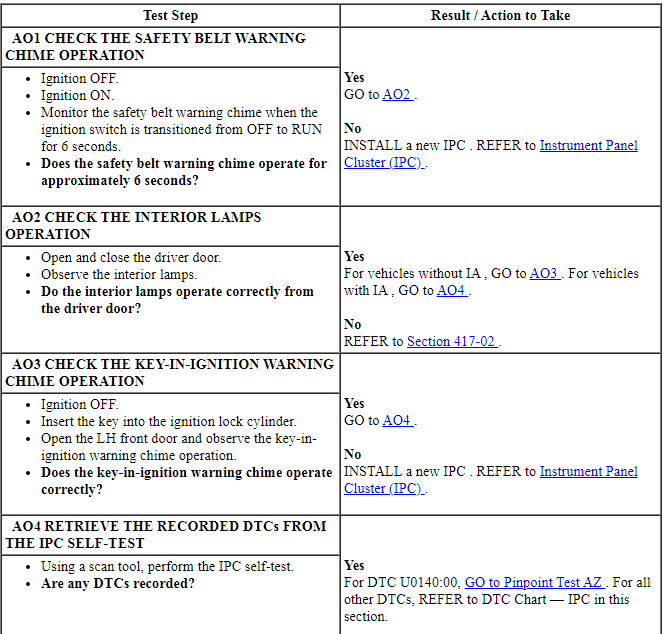

Pinpoint Test AP: The Key-In-Ignition Warning Chime Is Inoperative
Diagnostic Overview
Diagnostics in this manual assume a certain skill level and knowledge of Ford-specific diagnostic practices. Refer to Diagnostic Methods in Section 100-00 for information about these practices.
Refer to Wiring Diagrams Cell 60, Instrument Cluster for schematic and connector information.
Normal Operation and Fault Conditions
REFER to Key-In-Ignition Warning Chime in Warning Chimes.
BCM DTC Fault Trigger Conditions

-
Possible Sources
- Wiring, terminals or connectors
- Interior lighting concern
- Key-in-ignition warning switch (part of the ignition switch)
- BCM
- IPC
PINPOINT TEST AP: THE KEY-IN-IGNITION WARNING CHIME IS INOPERATIVE
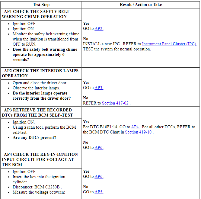
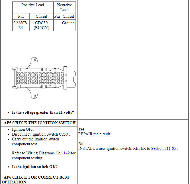
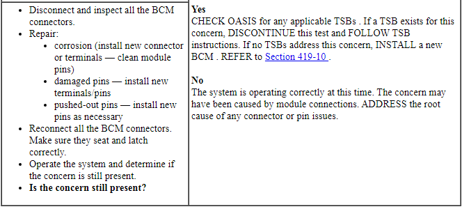
Pinpoint Test AQ: The Memory-Stored Feedback Chime Is Inoperative
Diagnostic Overview
Diagnostics in this manual assume a certain skill level and knowledge of Ford-specific diagnostic practices. Refer to Diagnostic Methods in Section 100-00 for information about these practices.
Normal Operation and Fault Conditions
REFER to Memory Feedback Chime in Warning Chimes.
-
Possible Sources
- Memory set feature concern
- DSM
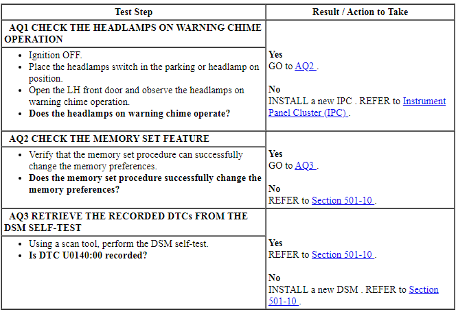
- IPC
PINPOINT TEST AQ: THE MEMORY-STORED FEEDBACK CHIME IS INOPERATIVE
Pinpoint Test AR: The Parking Brake Warning Chime Is Inoperative
Diagnostic Overview
Diagnostics in this manual assume a certain skill level and knowledge of Ford-specific diagnostic practices. Refer to Diagnostic Methods in Section 100-00 for information about these practices.
Normal Operation and Fault Conditions
REFER to Parking Brake Warning Chime in Warning Chimes.
-
Possible Sources
- Vehicle speed input concern
- Parking brake input concern
- BCM
- IPC
Visual Inspection And Diagnostic Pre-checks
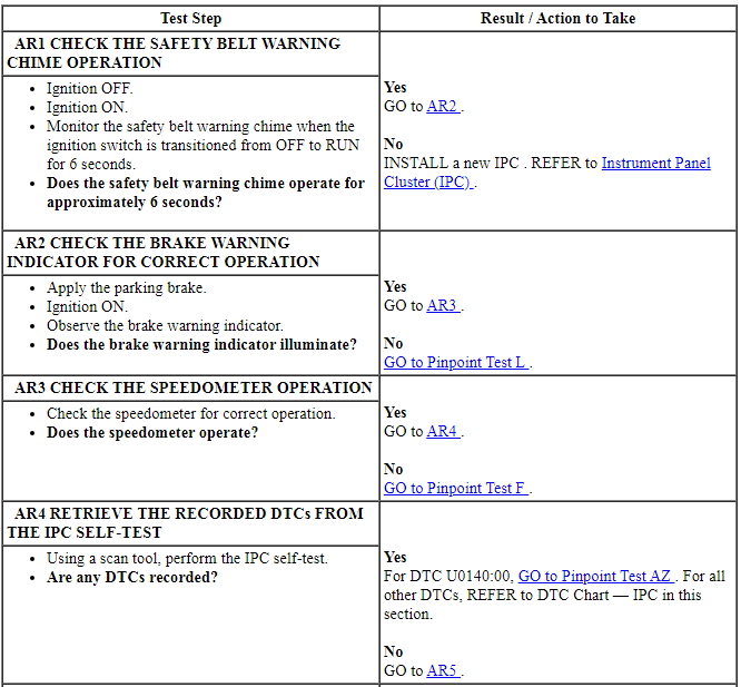
Check the operation of the parking brake warning chime operation with the vehicle moving at least 5 km/h (3 mph) and the parking brake slightly applied (just enough to turn the brake warning indicator on without damaging the rear brakes).
PINPOINT TEST AR: THE PARKING BRAKE WARNING CHIME IS INOPERATIVE

Pinpoint Test AS: The Safety Belt Warning Chime Or Belt-Minder Feature Chime Is Inoperative Or Always On
Diagnostic Overview
Diagnostics in this manual assume a certain skill level and knowledge of Ford-specific diagnostic practices. Refer to Diagnostic Methods in Section 100-00 for information about these practices.
Normal Operation and Fault Conditions
REFER to Safety Belt Warning Chime or Belt-Minder Feature in Warning Chimes.
-
Possible Sources
- Belt-Minder deactivated
- Safety belt indication concern
- Vehicle speed input concern
- RCM
- IPC
PINPOINT TEST AS: THE SAFETY BELT WARNING CHIME OR BELT-MINDER FEATURE CHIME IS INOPERATIVE OR ALWAYS ON
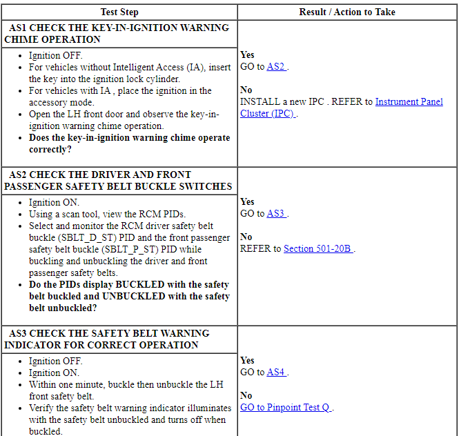
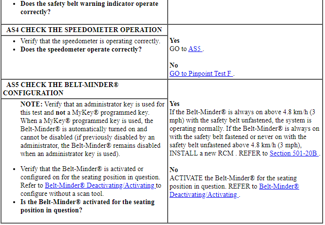
Pinpoint Test AT: The Turn Signal On Warning Chime Is Inoperative
Diagnostic Overview
Diagnostics in this manual assume a certain skill level and knowledge of Ford-specific diagnostic practices. Refer to Diagnostic Methods in Section 100-00 for information about these practices.
Normal Operation and Fault Conditions
REFER to Turn Signal On Warning Chime in Warning Chimes.
-
Possible Sources
- RH/LH turn signal indication concern
- IPC
PINPOINT TEST AT: THE TURN SIGNAL ON WARNING CHIME IS INOPERATIVE
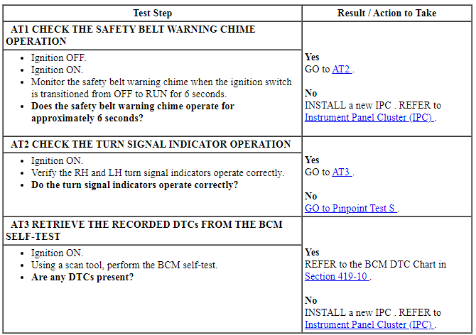
Pinpoint Test AU: The Turn Signal Left On Warning Chime Is Inoperative
Diagnostic Overview
Diagnostics in this manual assume a certain skill level and knowledge of Ford-specific diagnostic practices. Refer to Diagnostic Methods in Section 100-00 for information about these practices.
Normal Operation and Fault Conditions
REFER to Turn Signal Left On Warning Chime in Warning Chimes.
-
Possible Sources
- RH/LH turn signal indication concern
- Odometer input concern
- IPC
PINPOINT TEST AU: THE TURN SIGNAL LEFT ON WARNING CHIME IS INOPERATIVE
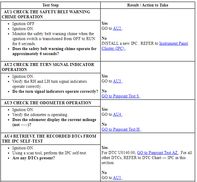

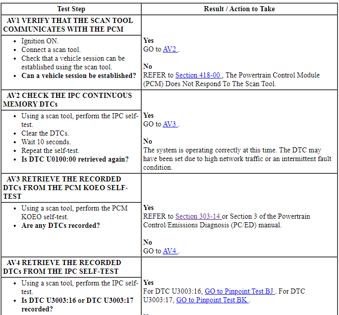
Pinpoint Test AV: DTC U0100:00
Diagnostic Overview
Diagnostics in this manual assume a certain skill level and knowledge of Ford-specific diagnostic practices. Refer to Diagnostic Methods in Section 100-00 for information about these practices.
Normal Operation and Fault Conditions
Once the IPC sets DTC U0100:00, multiple gauges or indicators are likely to be inoperative in the IPC. Other modules that require data from the IPC all set communication DTCs and may also exhibit system function concerns.
IPC DTC Fault Trigger Conditions

-
Possible Sources
- Communication concern
- Battery voltage concern
- PCM
- IPC
PINPOINT TEST AV: DTC U0100:00

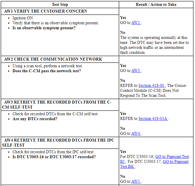
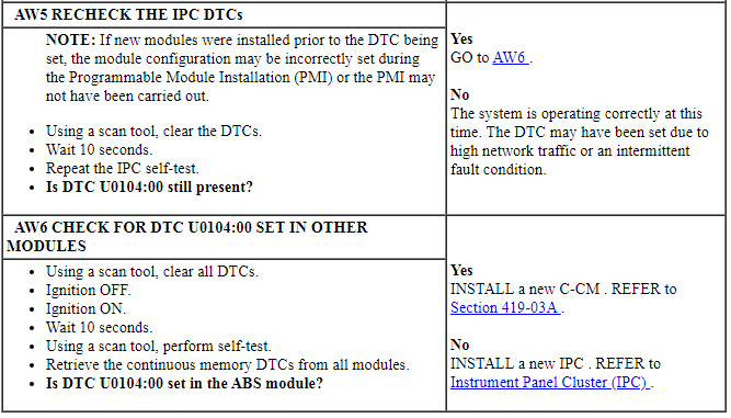
Pinpoint Test AW: DTC U0104:00
Diagnostic Overview
Diagnostics in this manual assume a certain skill level and knowledge of Ford-specific diagnostic practices. Refer to Diagnostic Methods in Section 100-00 for information about these practices.
Normal Operation and Fault Conditions
IPC DTC Fault Trigger Conditions

-
Possible Sources
- Communication concern
- Battery voltage concern
- C-CM
- IPC
PINPOINT TEST AW: DTC U0104:00
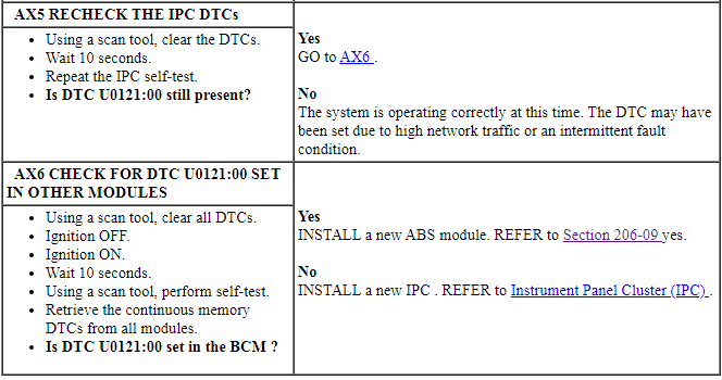
Pinpoint Test AX: DTC U0121:00
Diagnostic Overview
Diagnostics in this manual assume a certain skill level and knowledge of Ford-specific diagnostic practices. Refer to Diagnostic Methods in Section 100-00 for information about these practices.
Normal Operation and Fault Conditions
IPC DTC Fault Trigger Conditions

-
Possible Sources
- Communication concern
- Battery voltage concern
- ABS module
- IPC
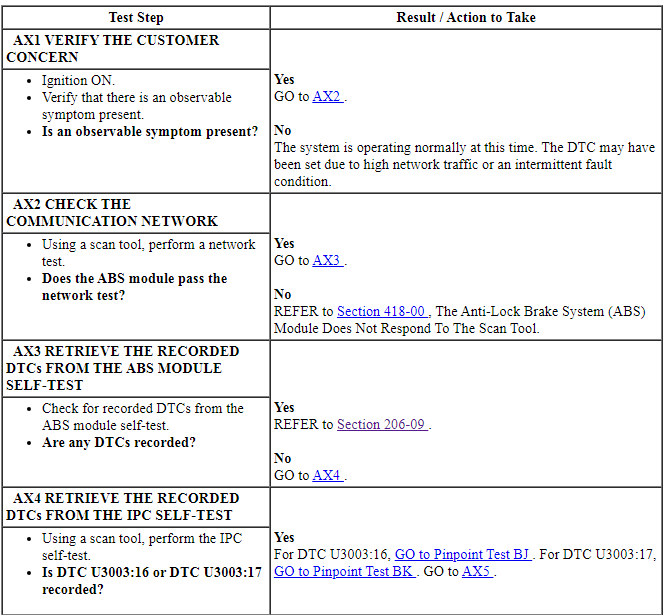
PINPOINT TEST AX: DTC U0121:00
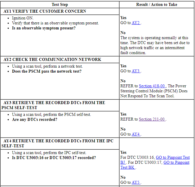
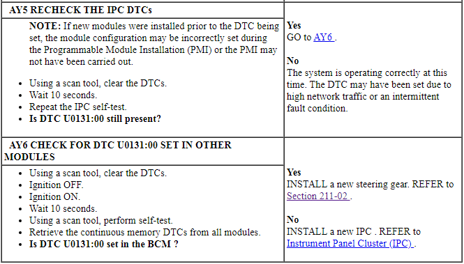
Pinpoint Test AY: DTC U0131:00
Diagnostic Overview
Diagnostics in this manual assume a certain skill level and knowledge of Ford-specific diagnostic practices. Refer to Diagnostic Methods in Section 100-00 for information about these practices.
Normal Operation and Fault Conditions
IPC DTC Fault Trigger Conditions

-
Possible Sources
- Communication concern
- Battery voltage concern
- PSCM
- IPC
PINPOINT TEST AY: DTC U0131:00
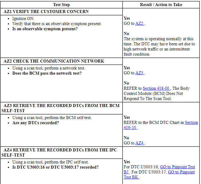
Pinpoint Test AZ: DTC U0140:00
Diagnostic Overview
Diagnostics in this manual assume a certain skill level and knowledge of Ford-specific diagnostic practices. Refer to Diagnostic Methods in Section 100-00 for information about these practices.
Normal Operation and Fault Conditions
IPC DTC Fault Trigger Conditions

-
Possible Sources
- Communication concern
- Battery voltage concern
- BCM
- IPC
PINPOINT TEST AZ: DTC U0140:00
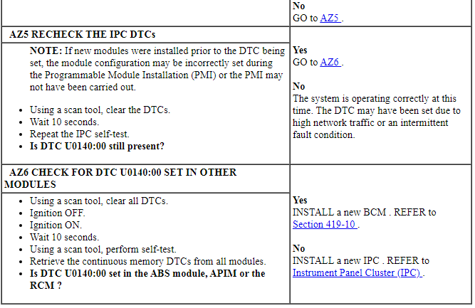
Pinpoint Test BA: DTC U0151:00
Diagnostic Overview
Diagnostics in this manual assume a certain skill level and knowledge of Ford-specific diagnostic practices. Refer to Diagnostic Methods in Section 100-00 for information about these practices.
Normal Operation and Fault Conditions
IPC DTC Fault Trigger Conditions

-
Possible Sources
- Communication concern
- Battery voltage concern
- RCM
- IPC
PINPOINT TEST BA: DTC U0151:00
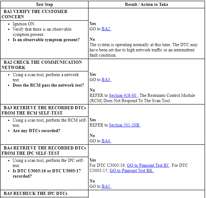
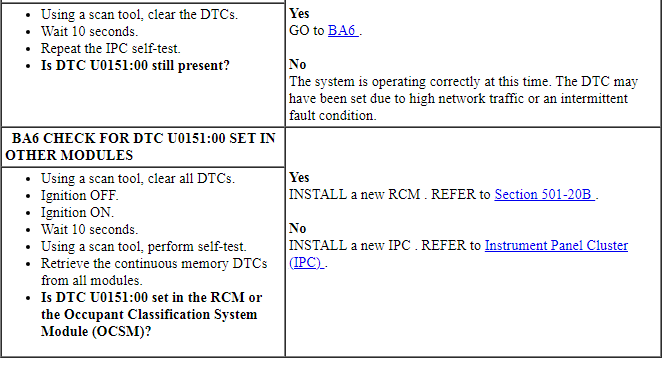
Pinpoint Test BB: DTC U0154:00
Diagnostic Overview
Diagnostics in this manual assume a certain skill level and knowledge of Ford-specific diagnostic practices. Refer to Diagnostic Methods in Section 100-00 for information about these practices.
Normal Operation and Fault Conditions
IPC DTC Fault Trigger Conditions

-
Possible Sources
- Communication concern
- Battery voltage concern
- OCSM
- IPC
PINPOINT TEST BB: DTC U0154:00
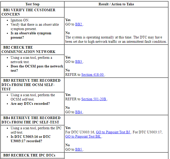

Pinpoint Test BC: DTC U0159:00
Diagnostic Overview
Diagnostics in this manual assume a certain skill level and knowledge of Ford-specific diagnostic practices. Refer to Diagnostic Methods in Section 100-00 for information about these practices.
Normal Operation and Fault Conditions
IPC DTC Fault Trigger Conditions

-
Possible Sources
- Communication concern
- Battery voltage concern
- RCM
- IPC
PINPOINT TEST BC: DTC U0159:00
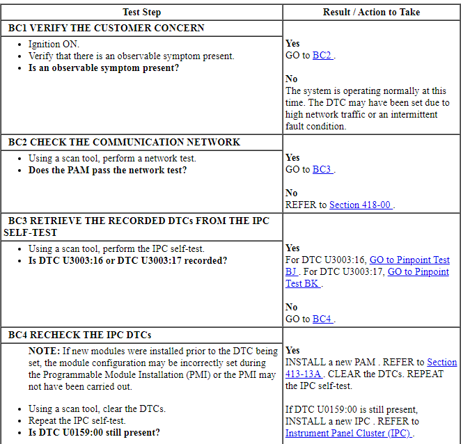

Pinpoint Test BD: DTC U0193:00
Diagnostic Overview
Diagnostics in this manual assume a certain skill level and knowledge of Ford-specific diagnostic practices. Refer to Diagnostic Methods in Section 100-00 for information about these practices.
Normal Operation and Fault Conditions
IPC DTC Fault Trigger Conditions

-
Possible Sources
- Communication concern
- Battery voltage concern
- Audo DSP module
- IPC
PINPOINT TEST BD: DTC U0193:00
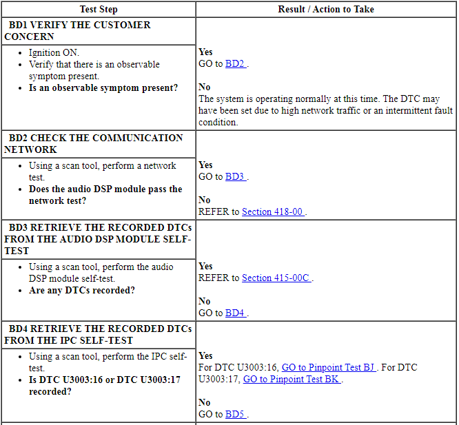
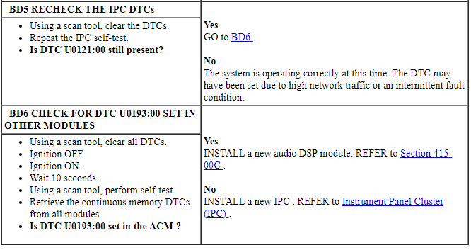
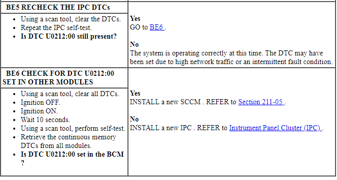
Pinpoint Test BE: DTC U0212:00
Diagnostic Overview
Diagnostics in this manual assume a certain skill level and knowledge of Ford-specific diagnostic practices. Refer to Diagnostic Methods in Section 100-00 for information about these practices.
Normal Operation and Fault Conditions
IPC DTC Fault Trigger Conditions

-
Possible Sources
- Communication concern
- Battery voltage concern
- SCCM
- IPC
PINPOINT TEST BE: DTC U0212:00
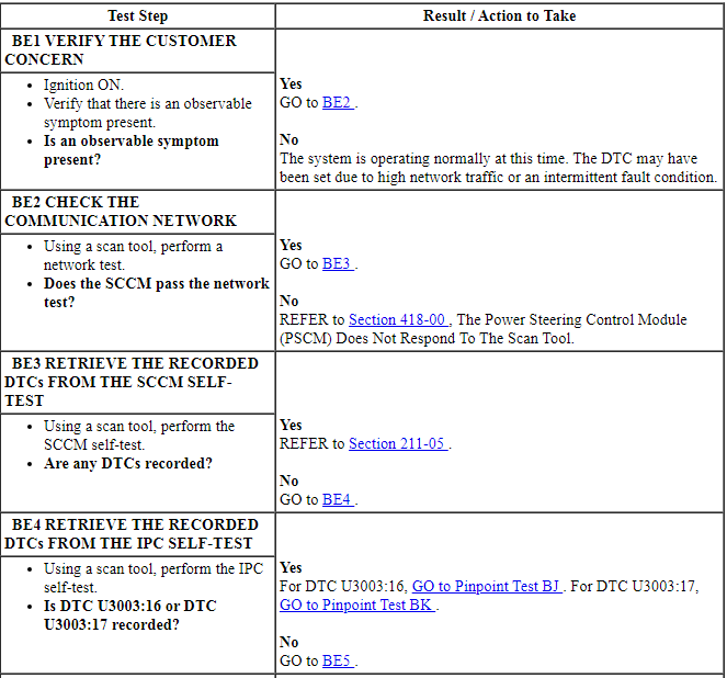
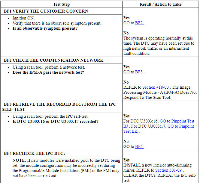
Pinpoint Test BF: DTC U023A:00
Diagnostic Overview
Diagnostics in this manual assume a certain skill level and knowledge of Ford-specific diagnostic practices. Refer to Diagnostic Methods in Section 100-00 for information about these practices.
Normal Operation and Fault Conditions
IPC DTC Fault Trigger Conditions

-
Possible Sources
- Communication concern
- Battery voltage concern
- Interior auto-dimming mirror
- IPC
PINPOINT TEST BF: DTC U023A:00

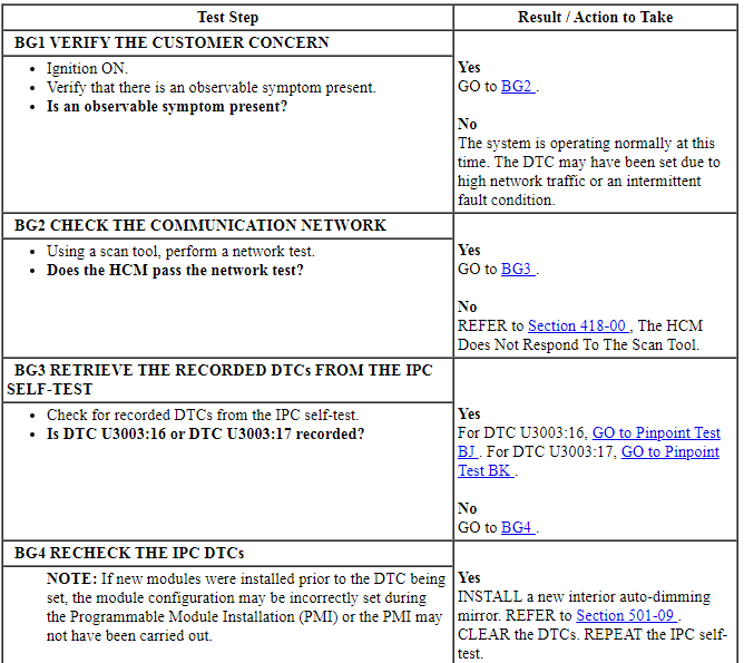
Pinpoint Test BG: DTC U0241:00
Diagnostic Overview
Diagnostics in this manual assume a certain skill level and knowledge of Ford-specific diagnostic practices. Refer to Diagnostic Methods in Section 100-00 for information about these practices.
Normal Operation and Fault Conditions
IPC DTC Fault Trigger Conditions

-
Possible Sources
- Communication concern
- Battery voltage concern
- Interior auto-dimming mirror
- IPC
PINPOINT TEST BG: DTC U0241:00

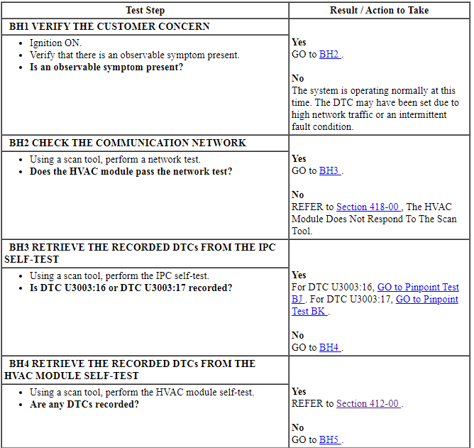
Pinpoint Test BH: DTC U0424:82
Diagnostic Overview
Diagnostics in this manual assume a certain skill level and knowledge of Ford-specific diagnostic practices. Refer to Diagnostic Methods in Section 100-00 for information about these practices.
Normal Operation and Fault Conditions
IPC DTC Fault Trigger Conditions

-
Possible Sources
- Communication concern
- Battery voltage concern
- HVAC module
- IPC
PINPOINT TEST BH: DTC U0424:82
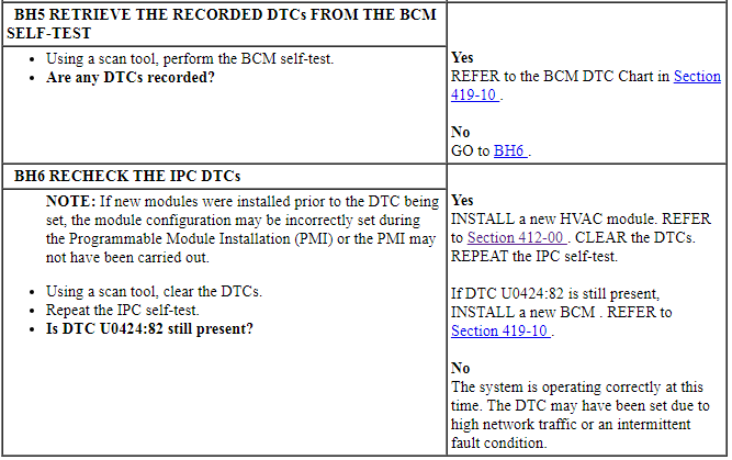
Pinpoint Test BI: DTC U1018:00
Diagnostic Overview
Diagnostics in this manual assume a certain skill level and knowledge of Ford-specific diagnostic practices. Refer to Diagnostic Methods in Section 100-00 for information about these practices.
Normal Operation and Fault Conditions
IPC DTC Fault Trigger Conditions

-
Possible Sources
- Communication concern
- Battery voltage concern
- GFM
- IPC
PINPOINT TEST BI: DTC U1018:00
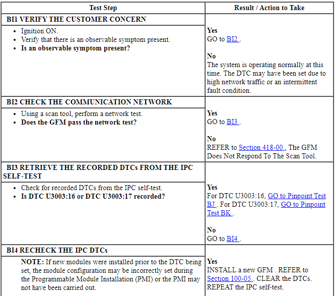

Pinpoint Test BJ: DTC U3003:16
Diagnostic Overview
Diagnostics in this manual assume a certain skill level and knowledge of Ford-specific diagnostic practices. Refer to Diagnostic Methods in Section 100-00 for information about these practices.
Refer to Wiring Diagrams Cell 60, Instrument Cluster for schematic and connector information.
Normal Operation and Fault Conditions
IPC DTC Fault Trigger Conditions

-
Possible Sources
- Wiring, terminals or connectors
- High circuit resistance
- Charging system concern
- IPC
PINPOINT TEST BJ: DTC U3003:16
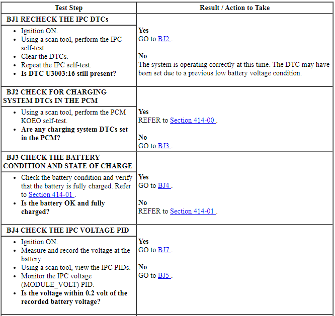
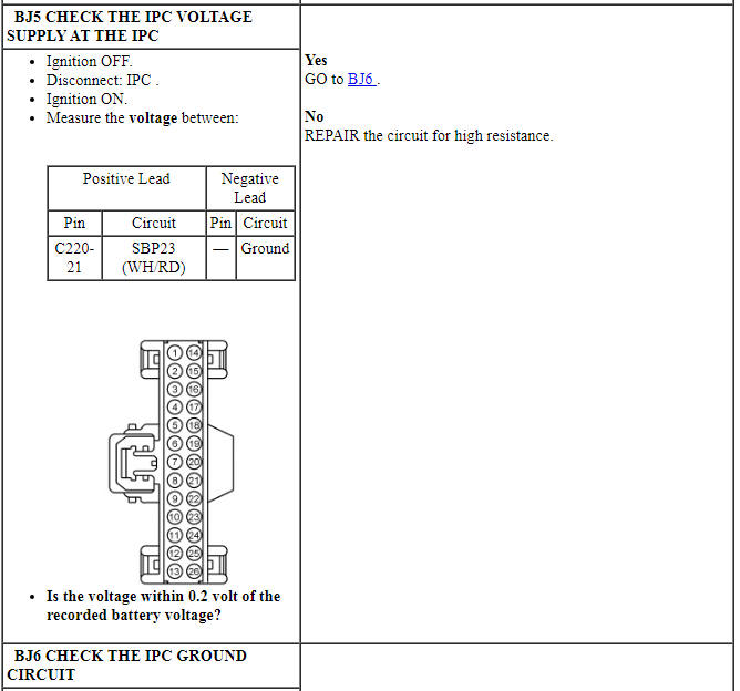
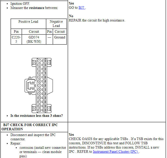

Pinpoint Test BK: DTC U3003:17
Diagnostic Overview
Diagnostics in this manual assume a certain skill level and knowledge of Ford-specific diagnostic practices. Refer to Diagnostic Methods in Section 100-00 for information about these practices.
Refer to Wiring Diagrams Cell 60, Instrument Cluster for schematic and connector information.
Normal Operation and Fault Conditions
IPC DTC Fault Trigger Conditions

-
Possible Sources
- Charging system concern
- IPC
PINPOINT TEST BK: DTC U3003:17
NOTE: DTC U3003:17 may be stored in the module memory due to past battery charging or vehicle jump starting events.
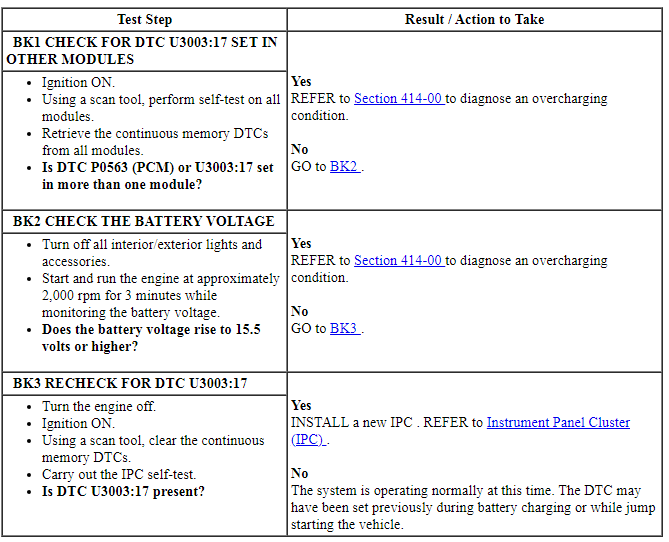
Pinpoint Test BL: The Lane Departure Warning System Display Is Inoperative
Diagnostic Overview
Diagnostics in this manual assume a certain skill level and knowledge of Ford-specific diagnostic practices. Refer to Diagnostic Methods in Section 100-00 for information about these practices.
Normal Operation and Fault Conditions
Refer to Lane Departure Warning System Display in Information And Message Center.
-
Possible Sources
- Lane departure warning system concern
- IPC
PINPOINT TEST BL: THE LANE DEPARTURE WARNING SYSTEM DISPLAY IS INOPERATIVE
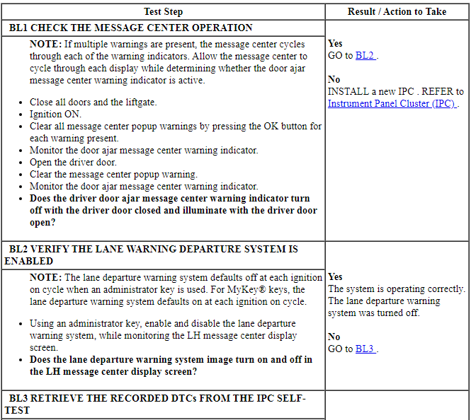

Pinpoint Test BM: The Lane Keeping Aid Warning Chime Is Inoperative
Diagnostic Overview
Diagnostics in this manual assume a certain skill level and knowledge of Ford-specific diagnostic practices. Refer to Diagnostic Methods in Section 100-00 for information about these practices.
Normal Operation and Fault Conditions
Refer to Lane Keeping Aid Warning Chime in Warning Chimes.
NOTE: The lane keeping aid warning chime only sounds to alert the driver that they have their hands off the steering wheel. Normal alerting is done through steering wheel vibrations, which cannot be felt when the drivers hands are not on the steering wheel.
-
Possible Sources
- Lane departure warning system concern
- IPM-A
- IPC
PINPOINT TEST BM: THE LANE KEEPING AID WARNING CHIME IS INOPERATIVE
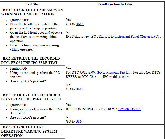

 Description and Operation
Instrument Panel Cluster (IPC)
Overview
Base IPC
Tachometer
Main menu navigation
Main menu text display
LH turn indicator
TPMS warning indicator
MIL
Stability-traction control indic ...
 General Procedures, Removal and Installation
GENERAL PROCEDURES
Belt-Minder Deactivating/Activating
NOTE: If you are using MyKey, the Belt-Minder cannot be disabled. If
the Belt-Minder has been previously disabled, it is re-enabled during ...
Other materials:
Economical driving
Fuel economy is affected by several things, such as how you drive, the
conditions you drive under and how you maintain your vehicle.
There are some things to keep in mind that may improve your fuel
economy:
• Accelerate and slow down in a smooth, moderate fashion.
• Drive at steady spee ...
Rear seats
Split-folding Rear Seat
WARNING: Before returning the seatback to its original position,
make sure that cargo or any objects are not trapped behind the
seatback. After returning the seatback to its original position, pull on
the seatback to make sure that it has fully latched. An unlatched seat
...
Power Steering
SPECIFICATIONS
Torque Specifications
a Refer to the procedure for the specification.
REMOVAL AND INSTALLATION
Steering Gear
Special Tool(s)
NOTE: 3.5L GTDI engine shown, 3.5L Ti-VCT, 3.7L Ti-VCT and 2.0L GTDI similar.
Removal
All vehicles
If in ...
