Automatic Transmission
Special Tool(s)
Material
DTC Chart
Diagnostics in this manual assume a certain skill level and knowledge of Ford-specific diagnostic practices. Refer to Diagnostic Methods in Section 100-00 for information about these practices.
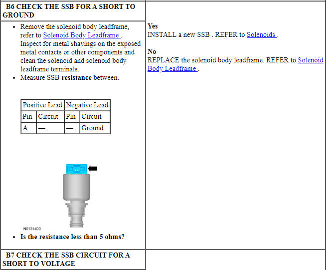
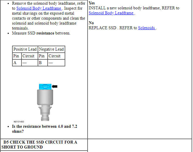
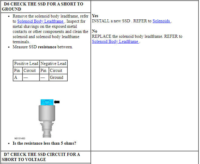
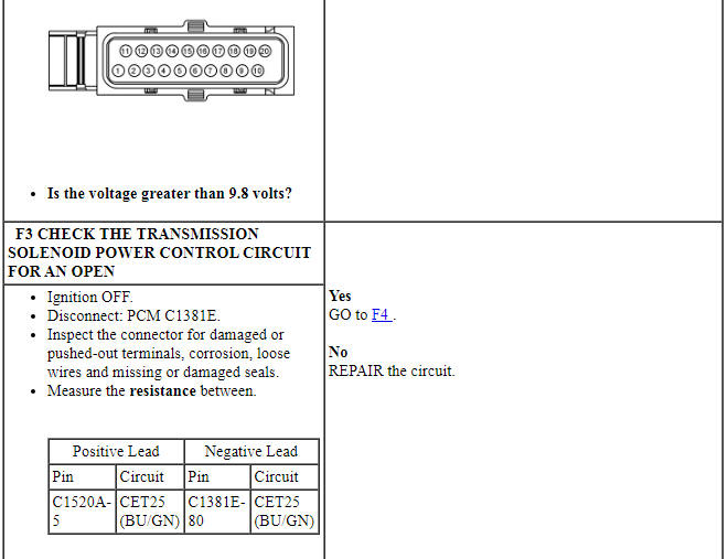
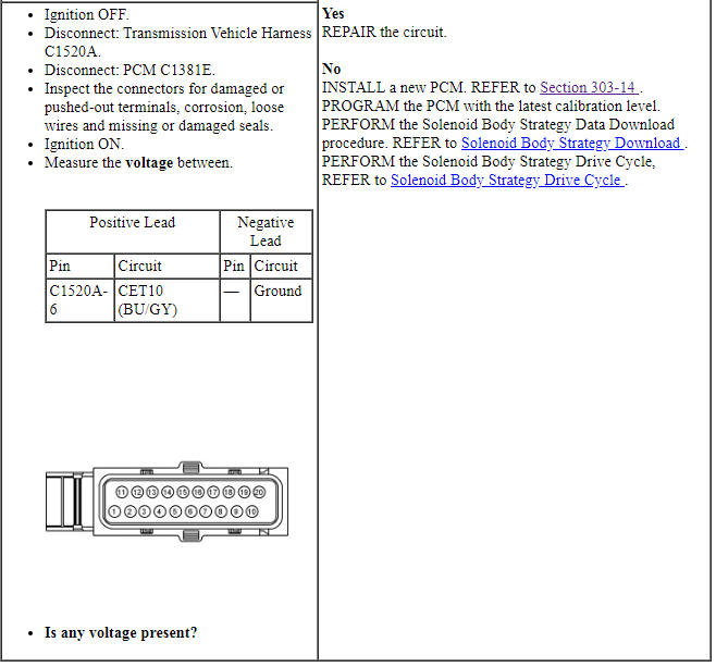
When the electrical connector or solenoid body is disconnected, inspect the connector for terminal condition, corrosion and contamination. Also inspect the connector seal for damage. Clean, repair or install new components as required.
Power is routed through the transmission solenoid power control relay (inside the PCM) to all transmission solenoids. If the power circuit to the transmission solenoids or the transmission solenoid power control relay fails open, then all solenoids are failed electrically off. Check for open, short to ground or the transmission connector disconnected. The transmission solenoid power control relay disables power to the transmission solenoids when certain transmission DTCs are set.
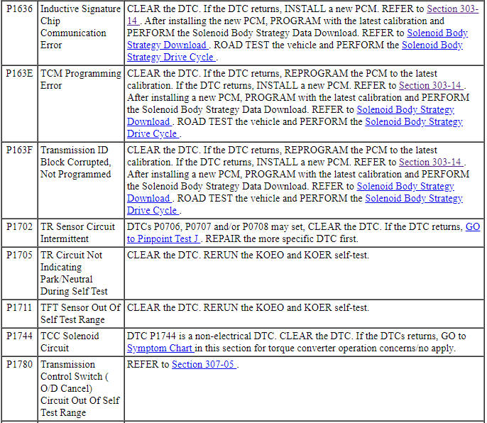
For all other DTCs, refer to Section 303-14.
Diagnostic PID Chart
Diagnostics in this manual assume a certain skill level and knowledge of Ford-specific diagnostic practices. Refer to Diagnostic Methods in Section 100-00 for information about these practices.
Module PID Chart
Symptom Chart
Diagnostics in this manual assume a certain skill level and knowledge of Ford-specific diagnostic practices. Refer to Diagnostic Methods in Section 100-00 for information about these practices.
In most circumstances, the PCM sets DTCs to help guide with diagnostics. Refer to the DTC Chart before using the symptom chart. The Condition column lists the vehicle condition. The Source column lists a detailed vehicle condition. The Action to column lists the action to be performed to determine the cause of the condition. Each action lists the components that can cause the system and the individual components in that system. The components are listed in order of disassembly. Use the list of components and the required action to focus on disassembly inspections for the root cause of the concern.
Diagnostic Routines
Diagnostics in this manual assume a certain skill level and knowledge of Ford-specific diagnostic practices. Refer to Diagnostic Methods in Section 100-00 for information about these practices.
NOTE: Without a voltage signal return to the PCM, the transmission solenoid power control relay is commanded off. By using a fused jumper wire between a transmission solenoid control circuit and the signal return circuit, the transmission solenoid power control relay circuit supplies power to the transmission solenoids when the ignition is cycled from off to on. Do not use a solenoid control circuit that may be at fault, refer to DTC Charts for a fault listing.
- Carry out OBD procedures KOEO and KOER.
- Retrieve and record all DTCs.
- Repair all non-transmission DTCs first.
- Repair all transmission DTCs second.
- Clear all continuous codes and attempt to repeat them.
- Repair all continuous codes.
- If only pass codes are obtained, refer to Component Tests in this section for further information and diagnosis.
Follow the diagnostic sequence to diagnose and repair the concern the first time.
Pinpoint Test A: P0750, P0753, P0754, P0973, P0974
Diagnostic Overview
Diagnostics in this manual assume a certain skill level and knowledge of Ford-specific diagnostic practices. Refer to Diagnostic Methods in Section 100-00 for information about these practices.
Refer to Wiring Diagrams Cell 30 for schematic and connector information.
Normal Operation and Fault Conditions
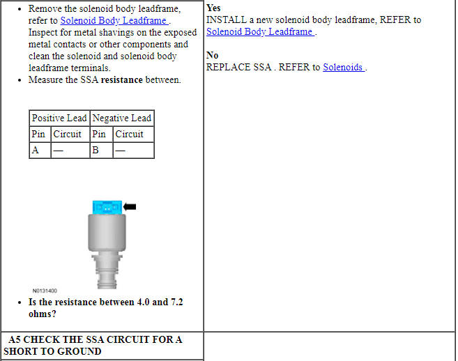
The PCM applies and releases the various clutches in the transmission by actuating the shift solenoids in the solenoid body. SSA is a VFS.
DTC Fault Trigger Conditions
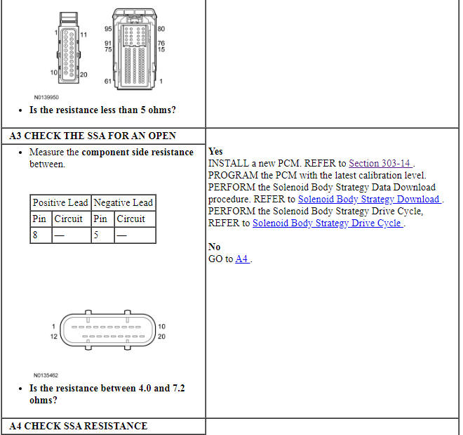
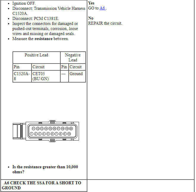
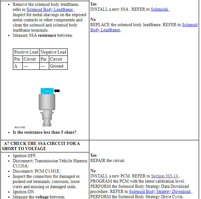
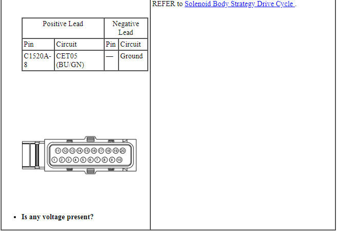
PINPOINT TEST A: SHIFT SOLENOID A
Pinpoint Test B: P0755, P0758, P0759, P0976, P0977
Diagnostic Overview
Diagnostics in this manual assume a certain skill level and knowledge of Ford-specific diagnostic practices. Refer to Diagnostic Methods in Section 100-00 for information about these practices.
Refer to Wiring Diagrams Cell 30 for schematic and connector information.
Normal Operation and Fault Conditions
The PCM applies and releases the various clutches in the transmission by actuating the shift solenoids in the solenoid body. SSB is a VFS.
DTC Fault Trigger Conditions
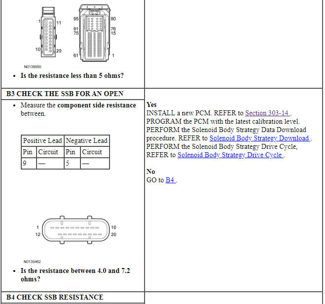
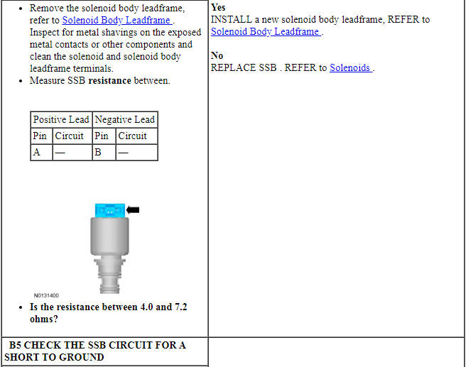
PINPOINT TEST B: SHIFT SOLENOID B

Pinpoint Test C: P0760, P0763, P0764, P0979, P0980
Diagnostic Overview
Diagnostics in this manual assume a certain skill level and knowledge of Ford-specific diagnostic practices. Refer to Diagnostic Methods in Section 100-00 for information about these practices.
Refer to Wiring Diagrams Cell 30 for schematic and connector information.
Normal Operation and Fault Conditions
The PCM applies and releases the various clutches in the transmission by actuating the shift solenoids in the solenoid body. SSC is a VFS.
DTC Fault Trigger Conditions
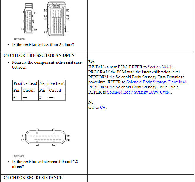
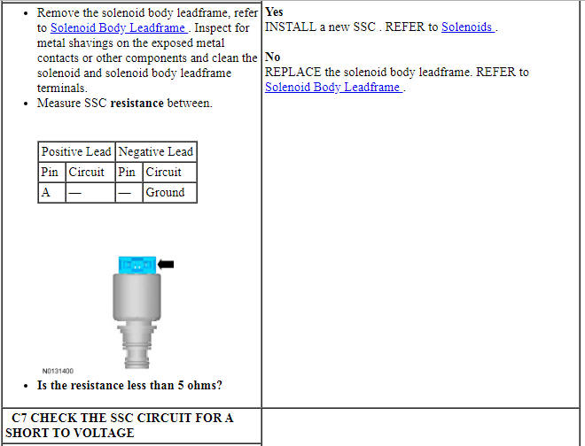
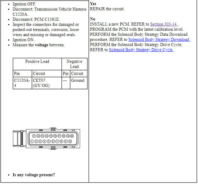
PINPOINT TEST C: SHIFT SOLENOID C


Pinpoint Test D: P0765, P0768, P0769, P0982, P0983
Diagnostic Overview
Diagnostics in this manual assume a certain skill level and knowledge of Ford-specific diagnostic practices. Refer to Diagnostic Methods in Section 100-00 for information about these practices.
Refer to Wiring Diagrams Cell 30 for schematic and connector information.
Normal Operation and Fault Conditions
The PCM applies and releases the various clutches in the transmission by actuating the shift solenoids in the solenoid body. SSD is a VFS.
DTC Fault Trigger Conditions
PINPOINT TEST D: SHIFT SOLENOID D
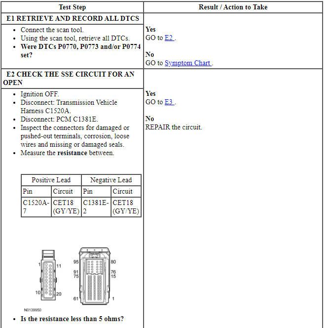
Pinpoint Test E: P0770, P0773, P0774
Diagnostic Overview
Diagnostics in this manual assume a certain skill level and knowledge of Ford-specific diagnostic practices. Refer to Diagnostic Methods in Section 100-00 for information about these practices.
Refer to Wiring Diagrams Cell 30 for schematic and connector information.
Normal Operation and Fault Conditions
SSE controls the multiplexing of the SSD low/reverse and overdrive clutch. If SSE fails off (no pressure) then 1st gear is failed to 4th gear. If clutch select valve 2 sticks in the default position then 1st gear with engine braking is failed to 4th gear and reverse is failed to neutral. SSE is an On/Off solenoid.
DTC Fault Trigger Conditions
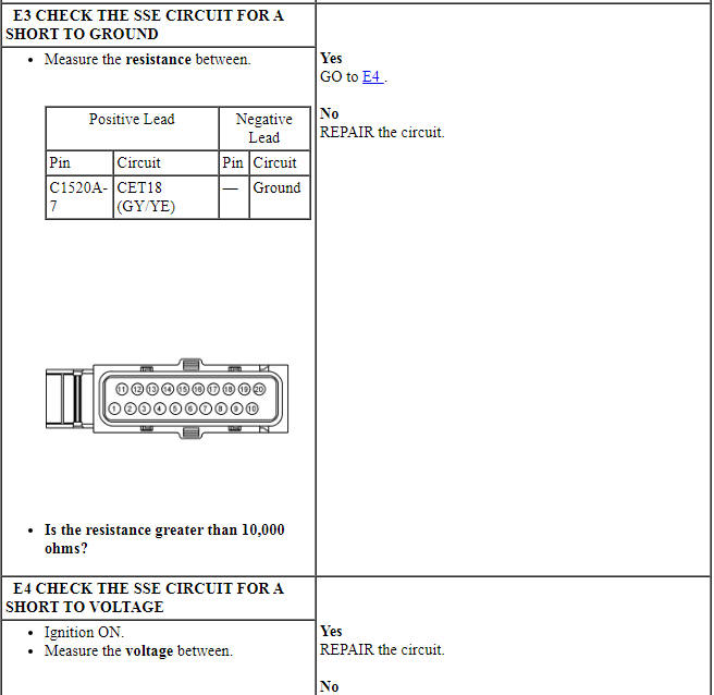
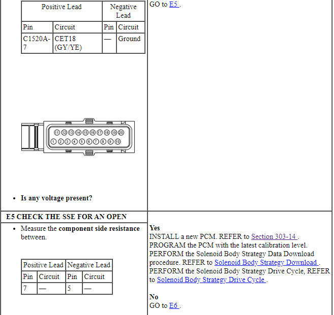
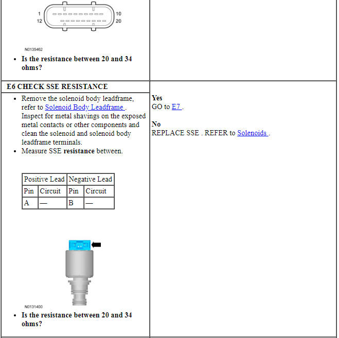
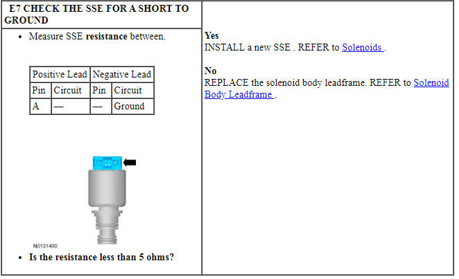
PINPOINT TEST E: SHIFT SOLENOID E
Pinpoint Test F: P0657
Diagnostic Overview
Diagnostics in this manual assume a certain skill level and knowledge of Ford-specific diagnostic practices. Refer to Diagnostic Methods in Section 100-00 for information about these practices.
Refer to Wiring Diagrams Cell 30 for schematic and connector information.
Normal Operation and Fault Conditions
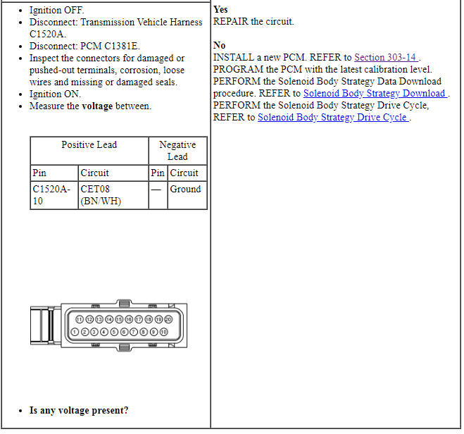
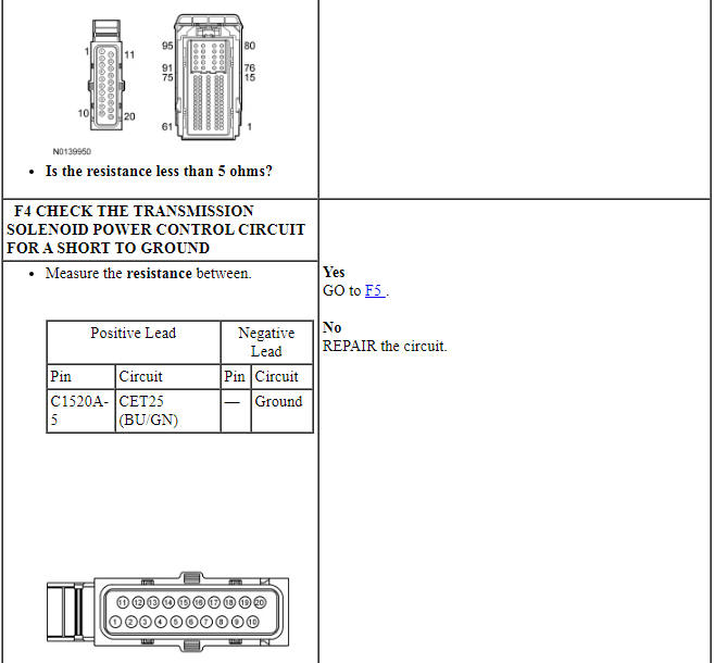
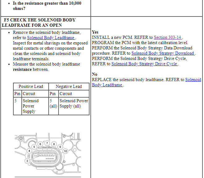
The transmission solenoid power control relay controls vehicle power to all solenoids. Power is routed through the transmission solenoid power control relay (inside the PCM) to all transmission solenoids. If the power circuit to the transmission solenoids or the transmission solenoid power control relay fails open, all solenoids are failed electrically off. Check for open, short to ground or the transmission connector disconnected. The transmission solenoid power control relay disables power to the transmission solenoids when certain transmission DTCs are set.
NOTE: Without a voltage signal return to the PCM, the transmission solenoid power control relay is commanded OFF. By using a fused jumper wire between a transmission solenoid control circuit and the signal return circuit, the transmission solenoid power control relay circuit supplies power to the transmission solenoids when the ignition is cycled from off to on. Do not use a solenoid control circuit that may be at fault, refer to DTC Charts in this section for a fault listing.
DTC Fault Trigger Conditions

PINPOINT TEST F: TRANSMISSION SOLENOID POWER CONTROL
Pinpoint Test G: P0710, P0711, P0712, P0713, P1711, P1783
Diagnostic Overview
Diagnostics in this manual assume a certain skill level and knowledge of Ford-specific diagnostic practices. Refer to Diagnostic Methods in Section 100-00 for information about these practices.
Refer to Wiring Diagrams Cell 30 for schematic and connector information.
Normal Operation and Fault Conditions
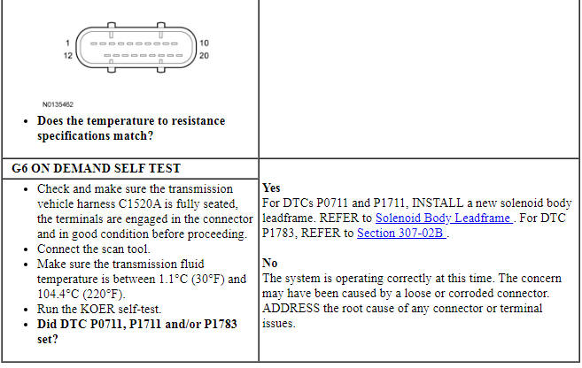
The TFT sensor is located in the solenoid body leadframe. The resistance value of the TFT sensor varies with temperature change. The PCM monitors the voltage drop across the TFT sensor to determine the temperature of the transmission fluid. When the ignition is turned to the RUN position, the PCM uses this initial input signal to determine whether a cold start shift schedule is necessary. The cold start shift schedule allows delayed shifts when the transmission fluid is cold. The PCM inhibits TCC operation at low transmission fluid temperatures and adjusts line pressure to temperature.
DTC Fault Trigger Conditions
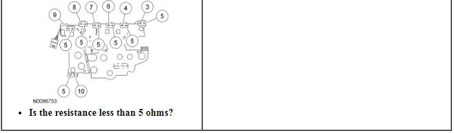
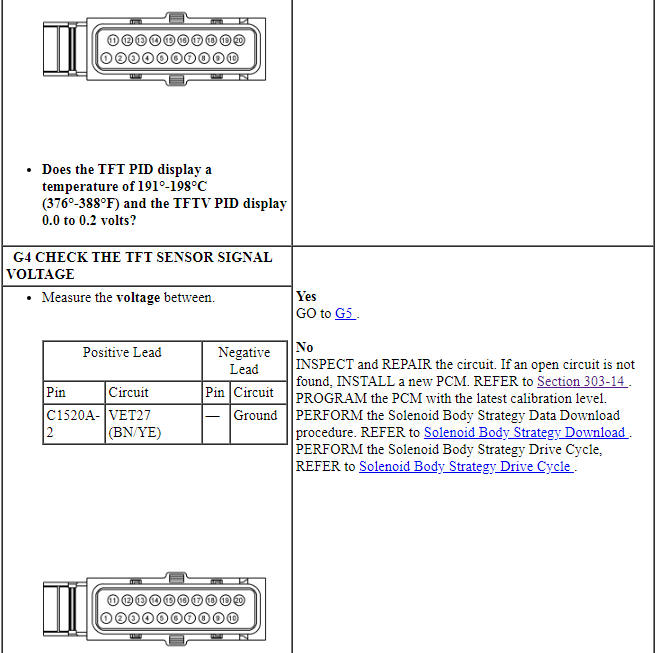
PINPOINT TEST G: TRANSMISSION FLUID TEMPERATURE SENSOR
Pinpoint Test H: P0740, P0742, P0743, P0744
Diagnostic Overview
Diagnostics in this manual assume a certain skill level and knowledge of Ford-specific diagnostic practices. Refer to Diagnostic Methods in Section 100-00 for information about these practices.
Refer to Wiring Diagrams Cell 30 for schematic and connector information.
Normal Operation and Fault Conditions
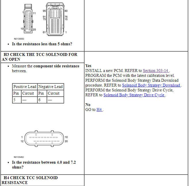
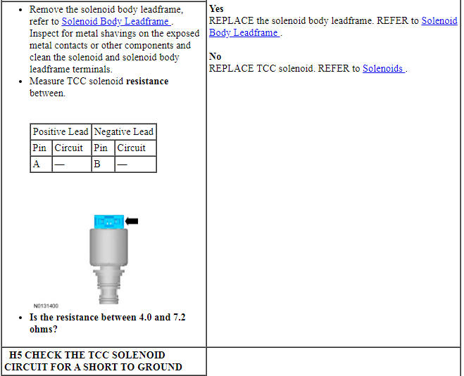
The PCM controls the TCC lock-up by varying the amount of current applied to the TCC solenoid. When no current is applied to the TCC solenoid, the TCC is fully released. When maximum current is applied, the TCC is fully applied.
DTC Fault Trigger Conditions
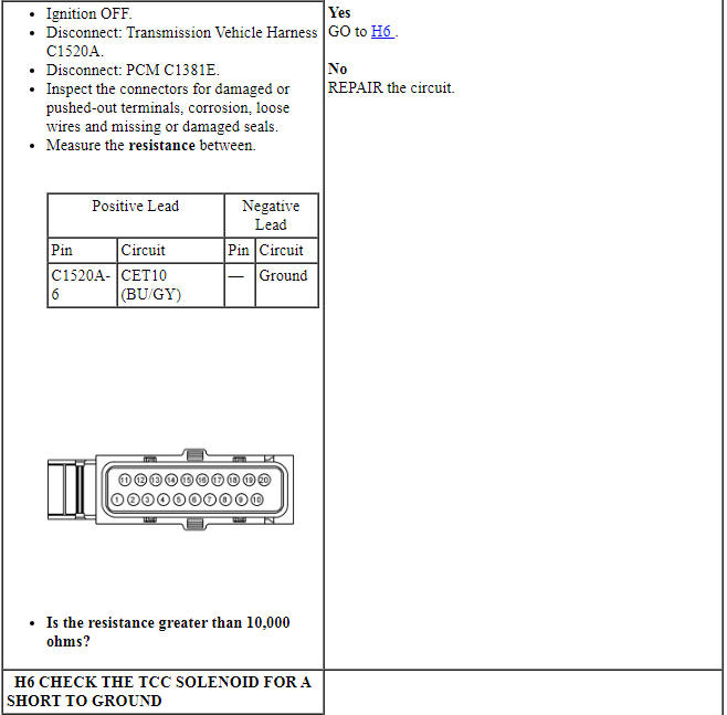
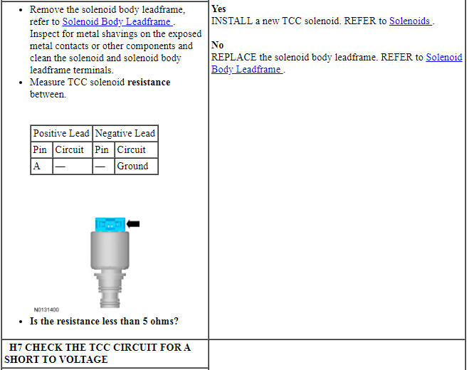
PINPOINT TEST H: TORQUE CONVERTER CLUTCH SOLENOID
Pinpoint Test I: P0748, P0960, P0962, P0963
Diagnostic Overview
Diagnostics in this manual assume a certain skill level and knowledge of Ford-specific diagnostic practices. Refer to Diagnostic Methods in Section 100-00 for information about these practices.
Refer to Wiring Diagrams Cell 30 for schematic and connector information.
Normal Operation and Fault Conditions
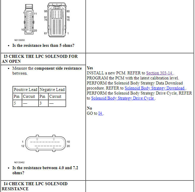
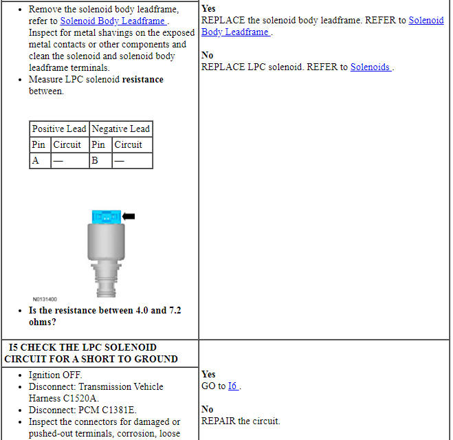
The PCM controls the hydraulic line pressure by varying the amount of current applied to the LPC solenoid. When no current is applied to the LPC solenoid, the LPC solenoid is fully opened, resulting in the maximum amount of hydraulic pressure to the main pressure regulator valve. When maximum current is applied, the LPC solenoid is fully closed, resulting in minimum pressure to the main pressure regulator valve.
DTC Fault Trigger Conditions
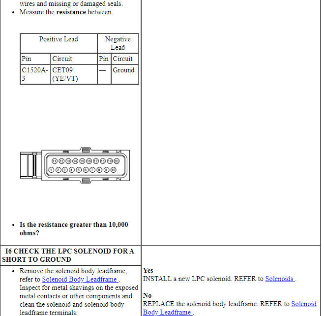
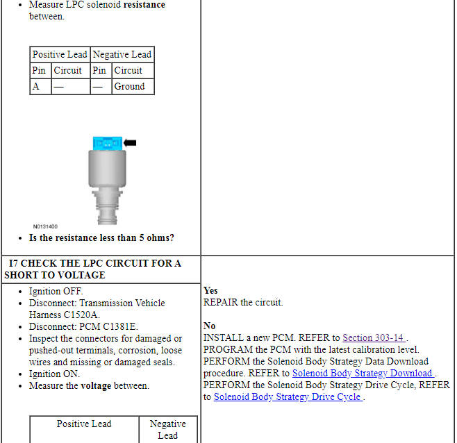
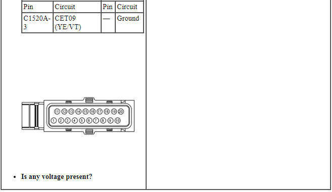
PINPOINT TEST I: LINE PRESSURE CONTROL SOLENOID
Pinpoint Test J: P0706, P0707, P0708, P1702, P1705, P1921
Diagnostic Overview
Diagnostics in this manual assume a certain skill level and knowledge of Ford-specific diagnostic practices. Refer to Diagnostic Methods in Section 100-00 for information about these practices.
Refer to Wiring Diagrams Cell 30 for schematic and connector information.
Normal Operation and Fault Conditions
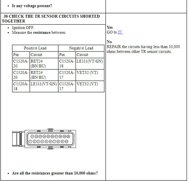
The TR sensor provides a fixed frequency duty cycle to the PCM for each manual control lever positions (PARK, REVERSE, NEUTRAL, DRIVE and LOW). The PCM uses the TR sensor signal for LPC , shift scheduling and TCC operation. The PCM transmits TR data on the HS-CAN to the BCM for engine start and reverse lamp operation.
DTC Fault Trigger Conditions
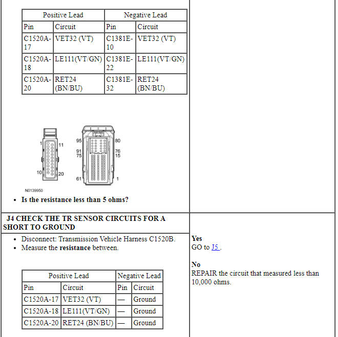
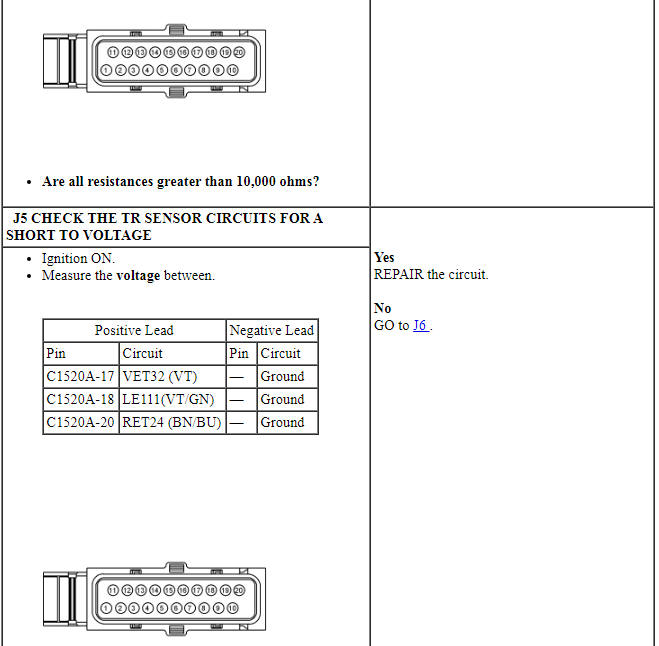
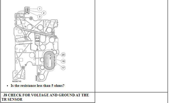
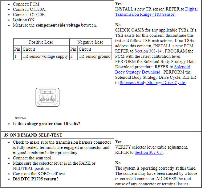
PINPOINT TEST J: TRANSMISSION RANGE SENSOR
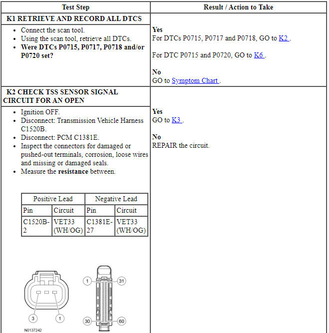
Pinpoint Test K: P0715, P0717, P0718
Diagnostic Overview
Diagnostics in this manual assume a certain skill level and knowledge of Ford-specific diagnostic practices. Refer to Diagnostic Methods in Section 100-00 for information about these practices.
Refer to Wiring Diagrams Cell 30 for schematic and connector information.
Normal Operation and Fault Conditions
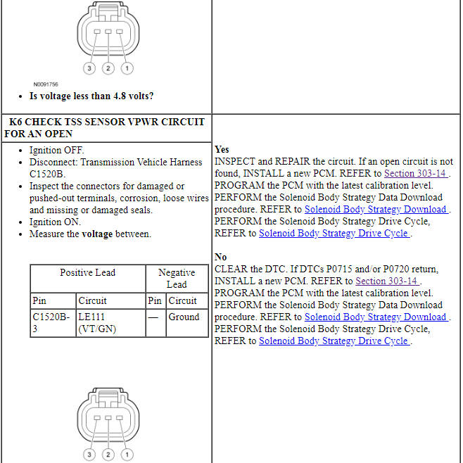
The TSS sensor is a Hall-effect sensor that sends a signal to the PCM that indicates transmission turbine shaft input speed. The TSS sensor provides converter turbine speed information for TCC strategy.
DTC Fault Trigger Conditions
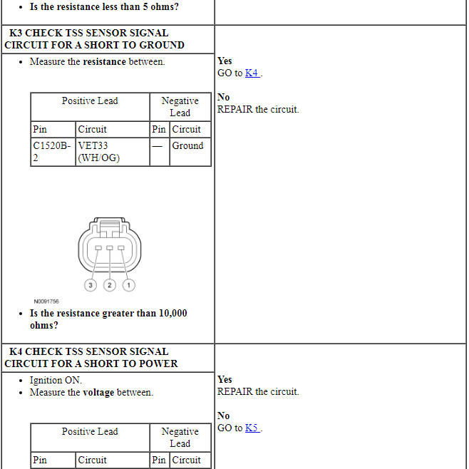
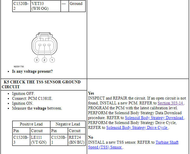
PINPOINT TEST K: TURBINE SHAFT SPEED SENSOR

Pinpoint Test L: P0720, P0721, P0722
Diagnostic Overview
Diagnostics in this manual assume a certain skill level and knowledge of Ford-specific diagnostic practices. Refer to Diagnostic Methods in Section 100-00 for information about these practices.
Refer to Wiring Diagrams Cell 30 for schematic and connector information.
Normal Operation and Fault Conditions
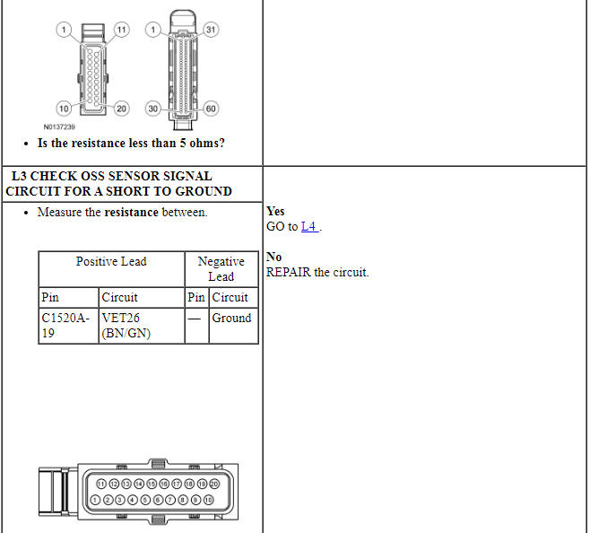
The OSS sensor is a Hall-effect sensor that sends a signal to the PCM that indicates transmission output shaft speed. The OSS sensor is used for TCC control and shift scheduling.
DTC Fault Trigger Conditions
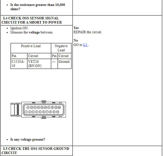
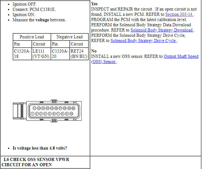
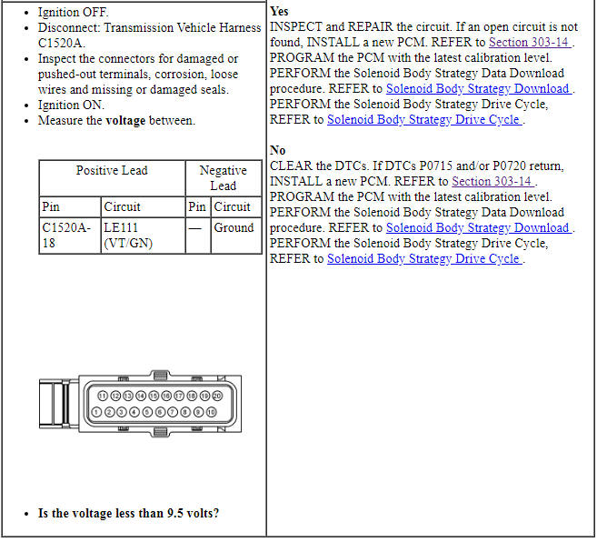
PINPOINT TEST L: OUTPUT SHAFT SPEED SENSOR
Component Tests
Line Pressure Test
NOTICE: Carry out the Line Pressure Test prior to carrying out the Stall Speed Test. If the line pressure is low at stall, do not carry out the Stall Speed Test or further transmission damage will occur. Do not maintain WOT in any transmission range for more than 5 seconds.
This test verifies the line pressure is within specification.
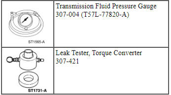
- Connect the Transmission Fluid Pressure Gauge 307-004 (T57L-77820-A) to the line pressure tap.
- Start the engine and check the line pressure. Refer to the Pressure Chart to determine if the line pressure is within specification.
Pressure Chart
- If the line pressure is not within specification, see the Line Pressure Diagnosis Chart for line pressure concern causes.
- When the pressure tests are complete, install the line pressure tap
plug.
- Tighten to 12 Nm (106 lb-in).
Line Pressure Diagnosis Chart
Stall Speed Test
WARNING: Block all wheels, set the parking brake and firmly apply the service brake to reduce the risk of vehicle movement during this procedure. Failure to follow these instructions may result in serious personal injury.
NOTICE: Carry out the Line Pressure Test prior to carrying out the Stall Speed Test. If the line pressure is low at stall, do not carry out the Stall Speed Test or further transmission damage will occur.
The Stall Speed Test checks:
- torque convertor operation and installation.
- holding ability of the forward clutch.
- reverse clutch.
- planetary OWC.
- engine driveability concerns.
Conduct this test with the engine coolant and transmission fluid at correct levels and at normal operating temperature.
Apply the park brake firmly for each Stall Speed Test.
Stall Speed Chart
- Connect the scan tool.
- NOTE: If the recorded rpm exceeds the maximum limits, release the
accelerator pedal immediately, clutch slippage is indicated.
In each of the following ranges Drive, Low and Reverse, press the accelerator pedal to WOT. Do not hold the throttle open for more than 5 seconds at a time.
- Note the results in each range.
- After each range, move the selector lever to NEUTRAL and run the engine at 1,000 rpm for about 15 seconds to cool the torque converter before conducting the next test.
- Use the Stall Speed Diagnosis Chart for corrective actions.
- NOTE: The stall speed in REVERSE will be lower.
If stall speeds were too high, see the Stall Speed Diagnosis Chart. If stall speeds were too low, first check engine idle speed and tune up. If engine is OK, remove torque converter and check TCC for slippage.
Stall Speed Diagnosis Chart
Leak Check Test
NOTE: When diagnosing transmission leaks, the source of the leak must be positively identified prior to repair. If the vehicle is driven extensively between adding the fluorescent additive and performing the leak test, the leaking oil can spread and make identifying the location of the leak difficult.
- Clean off any transmission fluid from the top and bottom of the torque converter housing, the front of the case and rear face of the engine and oil pan. Clean the torque converter area by washing with a nonflammable solvent and blow dry with compressed air.
- Add Dye-Lite ATF Power Steering Fluid Leak Detection Dye to the transmission fluid. Use one 30 ml (1 fl. oz) of dye solution for every 3.8 L (4 qt) of transmission fluid.
- Start and run the engine until the transmission reaches its normal operating temperature. Raise the vehicle on a hoist and run the engine occasionally shifting to the DRIVE and REVERSE ranges to increase pressure within the transmission. Using a black light, observe the back of the cylinder block and top of the torque converter housing for evidence of fluid leakage. Run the engine until transmission fluid leakage is evident and the probable source of leakage can be determined.
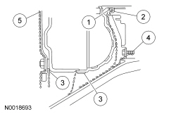
- If the source of the leak is obvious, repair as required. Leaks from the
torque converter housing can originate from several locations. The paths
which the fluid takes to reach the bottom of the torque converter housing
are shown in the illustration. The 5 steps following correspond with the
numbers in the illustration.
- Transmission fluid leaking by the converter hub seal lip will tend to move along the drive hub and onto the back of the torque converter. Except in the case of a total seal failure, transmission fluid leakage by the lip of the seal will be deposited on the inside of the torque converter housing only, near the outside diameter of the housing.
- Transmission fluid leakage by the outside diameter of the converter impeller hub seal and the case will follow the same path that leaks by the ID of the converter hub seal follow.
- Transmission fluid leakage from the converter cover weld or the converter-to-flexplate stud weld will appear at outside diameter of torque converter on the back face of the flexplate and in the converter housing only near the flexplate. If a converter-to-flexplate lug, lug weld or converter cover weld leak is suspected, remove the converter and pressure check.
- Transmission fluid leakage from the bolts inside the converter housing will flow down the back of the torque converter housing. Leakage may be from loose or missing bolts.
- Engine oil leaks from the rear main oil.
- Remove the torque converter.
- Using a black light, observe the torque converter housing. Inspect for evidence of dye from the pump bolts, pump seal, and torque converter hub seal. Repair as required.
- If the source of the leak is not evident, continue with this procedure to leak test the torque converter.
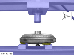
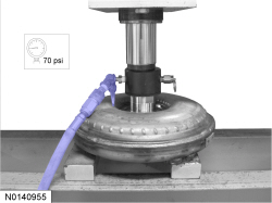
- Install the torque converter in the arbor press. Support the torque converter on the mounting pads.
- Install the Leak Tester, Torque Converter 307-421 into the torque converter hub.
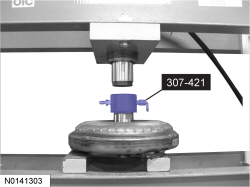
- Secure the press. Only apply enough force from the press to seal of the Leak Tester, Torque Converter 307-421 into the torque converter hub.
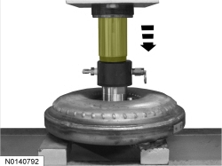
- Connect a compressed air supply to the Leak Tester, Torque Converter 307-421.
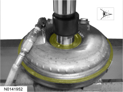
- With air pressure applied to the valve, inspect for leaks at the converter hub weld and seams. A soap bubble solution can be applied around those areas to aid in the diagnosis. If any leaks are present, install a new torque converter.
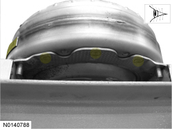
- With air pressure applied to the valve, inspect for leaks at the stud or mounting pad and balance weight welds. A soap bubble solution can be applied around those areas to aid in the diagnosis. If any leaks are present, install a new torque converter.
- After leaks are repaired, clean remaining transmission fluid dye from serviced areas.
Leak Check Test with Black Light
- NOTE: Dye-Lite ATF /Power Steering Fluid Leak Detection Dye is
used to detect a transmission fluid leak.
Add Dye-Lite ATF Power Steering Fluid Leak Detection Dye to the transmission fluid. Use one 30 ml (1.01 fl. oz) of dye solution for every 3.8 L (4.02 qt) of transmission fluid.
- Start and run the engine until the transmission reaches its normal operating temperature. Using a black light, observe the back of the cylinder block and top of the torque converter housing for evidence of fluid leakage. Raise the vehicle on a hoist and run the engine at fast idle, then at low idle, occasionally shifting to the DRIVE and REVERSE ranges to increase pressure within the transmission. Observe the front of the flexplate, back of the cylinder block (in as far as possible), inside the torque converter housing and the entire case until fluid leakage is evident and the probable source of leakage can be determined.
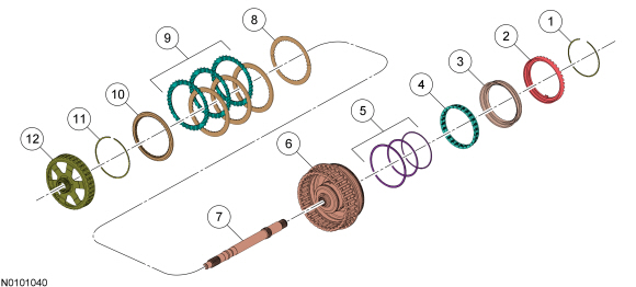
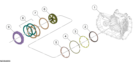
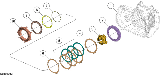
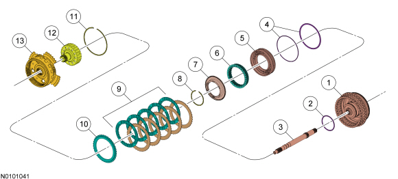
Forward Clutch System
For forward (1,2,3,4) clutch operation, Automatic Transmission.
Forward Clutch
 c
c
Direct Clutch System
For direct clutch (3, 5, R) operation, REFER to Automatic Transmission.
Direct Clutch System
Intermediate Clutch System
For intermediate (2, 6) clutch operation, REFER to Automatic Transmission.
Intermediate Clutch System
Low/Reverse Clutch System
For low/reverse clutch operation, REFER to Automatic Transmission.
Low/Reverse Clutch System
Overdrive Clutch System
For overdrive clutch system operation, REFER to Automatic Transmission.
Overdrive Clutch System
Low One Way Clutch
For low OWC system operation, REFER to Automatic Transmission.
 Specifications, Description and Operation
SPECIFICATIONS
Material
Torque Specifications
a Refer
to the procedure for the specification.
General Specifications
Solenoid Operation Chart
a Turns
on above 8 km/h (5 mph).
b ...
 General Procedures
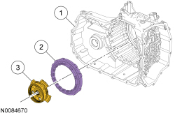
Solenoid Body Identification Procedure
Original Solenoid Body Service Tag
Using the scan tool, select Powertrain, Transmission and Transmission
Solenoid Body Identification from the toolbox icon a ...
Other materials:
Disassembly and Assembly of Subassemblies
Cylinder Head
Special Tool(s)
Material
Disassembly
NOTICE: During engine repair procedures, cleanliness is extremely
important. Any foreign material, including any material created while cleaning
gasket surfaces, that enters the oil passages, coolant passages or the oil pan
can cause en ...
Refueling
WARNING: Fuel vapor burns violently and a fuel fire can cause
severe injuries. To help avoid injuries to you and others:
• Read and follow all the instructions on the pump island.
• Turn off your engine when you are refueling.
• Do not smoke if you are near fuel or refueling your vehic ...
Opening and closing the hood
1. Inside the vehicle, pull the hood
release handle located under the
bottom of the instrument panel near
the steering column.
2. Go to the front of the vehicle and
release the auxiliary latch that is
located under the front center of
the hood.
3. Lift the hood. ...
