SPECIFICATIONS
Material
Torque Specifications
a Refer to the procedure for the specification.
General Specifications
Solenoid Operation Chart
b Turns off above 8 km/h (5 mph).
CB = Clutch brake
NC = Normally closed
NH = Normally high
NL = Normally low
Pressure Chart
Clutch Application Chart
H = Holding
D = Driven
Stall Speed Chart
Gear Ratio Chart
Shift Speeds
DESCRIPTION AND OPERATION
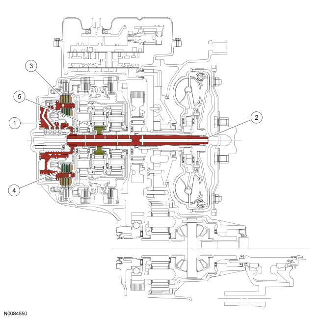
Automatic Transmission
Componenet Location
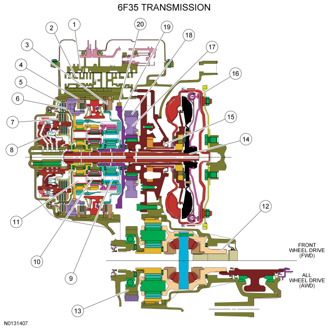
- Solenoid body
- Valve body
- Forward clutch (clutch brake 1,2,3,4)
- Low/reverse clutch (clutch brake L/R)
- Intermediate clutch (clutch brake 2,6)
- Low OWC
- Direct clutch (drive clutch 3,5,R)
- Overdrive clutch (drive clutch 4,5,6)
- Rear planetary assembly
- Center planetary assembly
- Front planetary assembly
- Final drive carrier and differential assembly
- Drive chain driven sprocket
- Input shaft assembly and direct/overdirve clutch hub
- Pump assembly
- Torque converter
- Drive chain sprocket
- Drive chain
- Park gear
- Park pawl
Overview
This automatic transmission is a 6-speed transmission with electronic shift control. It is designed for operation in a transverse powertrain for FWD and AWD vehicles.
This transmission has a 4-element torque converter design, which includes a TCC and a geartrain with 3 planetary gearsets.
The hydraulic control system of this transmission uses 7 electronically controlled solenoids for:
- Shift feel (through line pressure control and shift pressure control)
- Shift scheduling and timing
- TCC operation
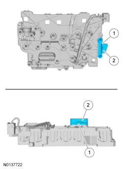
Identification Tags
Identification Tag Location
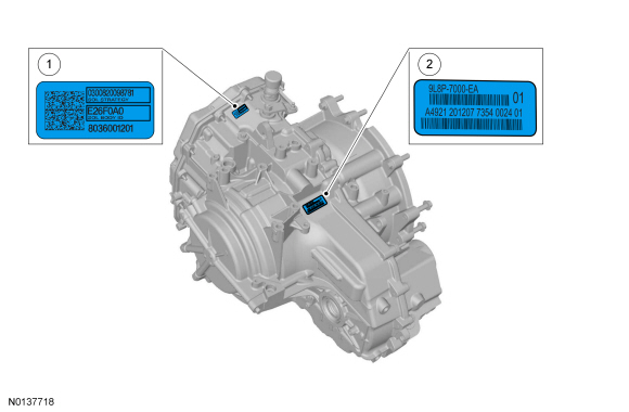
- Solenoid body identification tag
- Transmission identification tag
Transmission Identification Tag
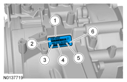
- Transmission part number
- Bar code 1
- Assembly plant line shift
- Transmission build date (DDMMYY)
- Transmission serial number
- Bar code 2
When servicing the transmission, use the transmission identification tag located on top of the transmission case.
Original Solenoid Body Tag
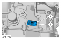
- 13 - digit solenoid body strategy
- 7 - digit solenoid body identification
The solenoid body strategy is programmed into the PCM to control the shift, LPC and TCC solenoids to prevent harsh shifts. The solenoid body tag on the transmission case contains the 13-digit solenoid body strategy and the 7-digit solenoid body identification.
Replacement Solenoid Body Tag
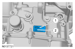
- 13 - digit solenoid body strategy
- 7 - digit solenoid body identification
When a new solenoid body is installed, a new solenoid body strategy file is downloaded into the PCM. A replacement solenoid body tag is supplied with the new solenoid body which contains the 13-digit solenoid body strategy and the 7-digit solenoid body identification. The new tag is placed over the original solenoid body tag.
Solenoid Body Identification and Strategy
- 13 - digit solenoid body strategy
- 7 - digit solenoid body identification
If the solenoid body strategy printed on the solenoid body connector does not match the solenoid body tag, a new solenoid body must be installed and the solenoid body strategy must be downloaded into the PCM or harsh shifts will result.
Solenoid Band Number
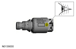
The solenoids are calibrated from the factory and are not all the same. The solenoids can be replaced separately, but only with a replacement solenoid with a injector nozzle and band number that matches the solenoid being replaced. When solenoid(s) are replaced, the new solenoid band number must match the old solenoid band number. The band number is next to the two-dimensional matrix barcode on the side of the solenoid and will be a 1, 2, 3, 4 or 5.
System Operation
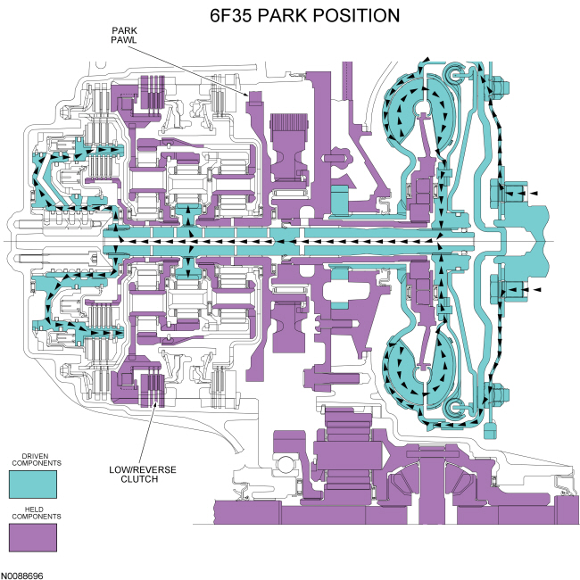
Park
Park Clutch Application Chart
H = Holding
Park Position Solenoid Operation Chart
NC = Normally Closed
NH = Normally High
NL = Normally Low
Powerflow- With the selector lever in PARK, the low/reverse clutch holds the rear planetary carrier/center ring gear stationary.
- The park pawl holds the rear ring/front planetary carrier stationary.
- The turbine shaft drives the center sun gear.
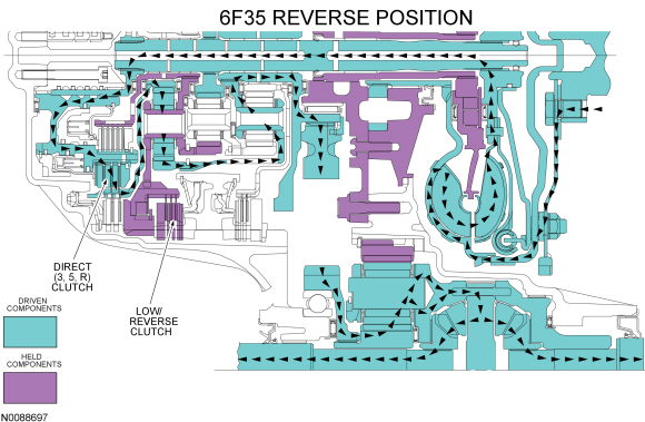
Reverse
Reverse Clutch Application Chart

H = Holding
D = Driving
Reverse Position Solenoid Operation Chart
NC = Normally Closed
NH = Normally High
NL = Normally Low
-
Powerflow
- With the selector lever in REVERSE, the low/reverse clutch holds the rear planetary carrier/center ring gear stationary.
- The direct clutch drives the rear sun gear.
- The rear ring/front planetary carrier transfers torque to the output hub in a reverse direction with a ratio of 2.88.
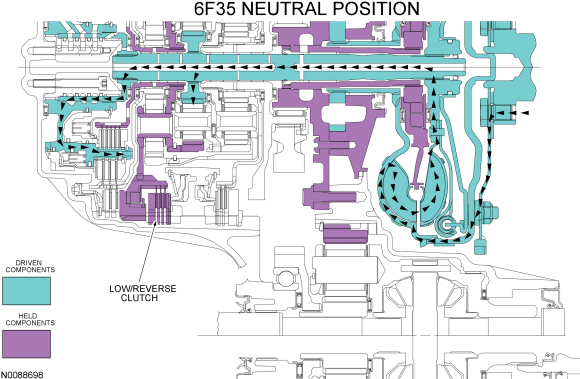
Neutral
Neutral Clutch Application Chart
H = Holding
Neutral Position Solenoid Operation Chart
NC = Normally Closed
NH = Normally High
NL = Normally Low
-
Powerflow
- With the selector lever in NEUTRAL, the low/reverse clutch holds the rear planetary carrier/center ring gear stationary.
- The turbine shaft drives the center sun gear.
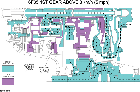
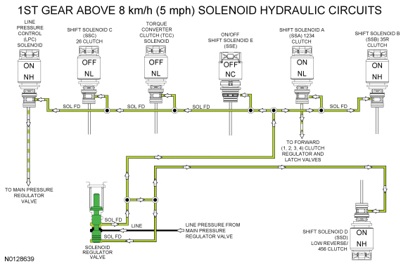
1st Gear
NOTE: The transmission operates differently in 1st gear above and below 8 kmh (5 mph). Transmission operation is the same below 8 kmh (5 mph) and in the LOW position.
1st Gear Above 8 kmh (5 mph) Clutch Application Chart
H = Holding
1st Gear LOW Position and Below 8 kmh (5 mph) Clutch Application Chart
H = Holding
1st Gear Above 8 kmh (5 mph) Solenoid Operation Chart
NC = Normally Closed
NH = Normally High
NL = Normally Low
1st Gear LOW Position and Below 8 kmh (5 mph) Solenoid Operation Chart
NC = Normally Closed
NH = Normally High
NL = Normally Low
-
Powerflow
- In first gear, the forward clutch holds the front sun gear stationary.
- The rear planetary carrier/center ring gear is held stationary by the low OWC and/or the low reverse (1, R) clutch.
- The turbine shaft transfers torque to the center sun gear. The center sun gear transfers the torque to the center planetary carrier/front ring gear. The front ring gear transfers torque to the front planetary carrier/rear ring gear and the output hub to produce a ratio of 4.48.
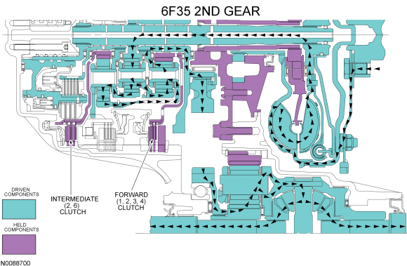
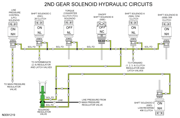
2nd Gear
2nd Gear Clutch Application Chart
H = Holding
2nd Gear Solenoid Operation Chart
NC = Normally Closed
NH = Normally High
NL = Normally Low
Powerflow- In second gear the forward clutch holds the front sun gear stationary.
- The intermediate clutch holds the rear sun gear stationary.
- The turbine shaft transfers torque to the center sun gear. The center sun gear transfers torque to the center ring gear/rear planetary carrier.
- The rear planetary carrier transfers the torque to the rear ring gear/front planetary carrier and the output hub to produce a gear ratio of 2.87.
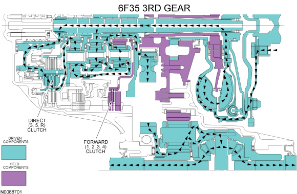
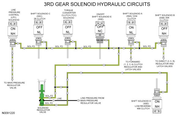
3rd Gear
3rd Gear Clutch Application Chart
H = Holding
D = Driving
3rd Gear Solenoid Operation Chart
NC = Normally Closed
NH = Normally High
NL = Normally Low
-
Powerflow
- In third gear the forward clutch holds the front sun gear stationary.
- The direct clutch drives the rear sun gear.
- Power flows from the center sun gear to the center planetary carrier/front ring gear. From there, torque is transferred to the rear ring gear/front planetary carrier.
- Power also flows from the rear sun gear to the rear ring gear/front planetary carrier.
- The two inputs to the front planetary carrier combine and transfer torque to the output hub to produce a gear ratio of 1.84.
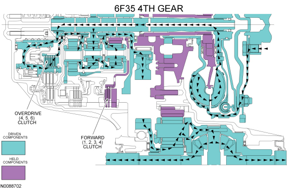
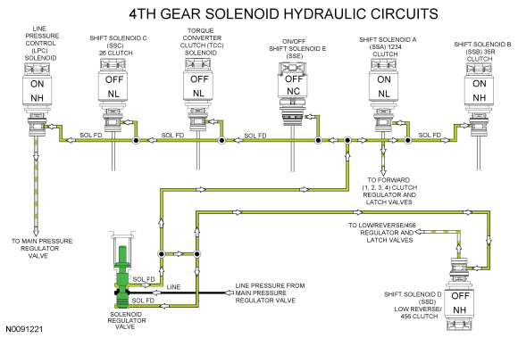
4th Gear
4th Gear Clutch Application Chart
H = Holding
D = Driving
4th Gear Solenoid Operation Chart
NC = Normally Closed
NH = Normally High
NL = Normally Low
-
Powerflow
- In fourth gear the forward clutch holds the front sun gear stationary.
- The overdrive clutch drives the rear planetary carrier/center ring gear.
- Power flows from turbine shaft to the center sun gear and center ring gear.
- The two inputs to the center planetary carrier combine and transfer torque to the front ring gear.
- The front ring gear transfers the torque to the front planetary carrier and onto the output hub to produce a gear ratio of 1.41.
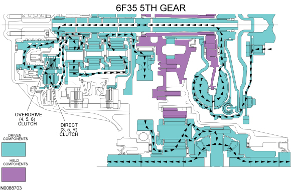
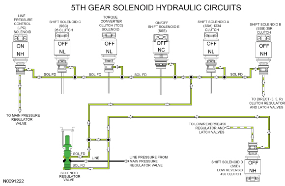
5th Gear
5th Gear Clutch Application Chart
D = Driving
5th Gear Solenoid Operation Chart
NC = Normally Closed
NH = Normally High
NL = Normally Low
-
Powerflow
- In fifth gear the overdrive clutch drives the rear planetary carrier/center ring gear.
- The direct clutch drives the rear sun gear.
- The turbine shaft transfers torque to the center sun gear, rear sun gear, and rear planetary carrier/center ring gear.
- The torque from the three inputs locks the three planetary gearsets which produces a gear ratio of 1 to 1
-
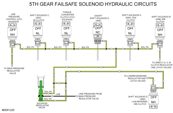
Fail-safe Mode
- Because both SSD and SSB apply the clutches they control when they are turned OFF, 5th gear is the fail-safe.
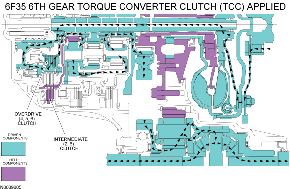
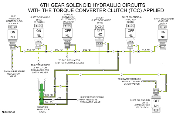
6th Gear
6th Gear Clutch Application Chart
H = Holding
D = Driving
6th Gear Solenoid Operation Chart
NC = Normally Closed
NH = Normally High
NL = Normally Low
-
Powerflow
- In sixth gear the overdrive clutch drives the rear planetary carrier/center ring gear.
- The intermediate clutch holds the rear sun gear.
- The torque from the rear planetary carrier is transferred to the rear ring gear/front planetary carrier and the output hub which produces a gear ratio of 0.74.
Electrical System
Component Location
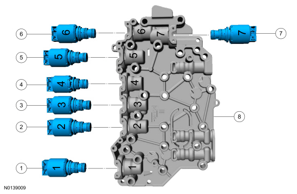
The solenoid body contains 5 shift solenoids, 1 TCC solenoid and 1 LPC solenoid.
Solenoid Body
- LPC
- SSC
- TCC
- SSE ON/OFF solenoid
- SSA
- SSB
- SSD
- Solenoid body
System Operation
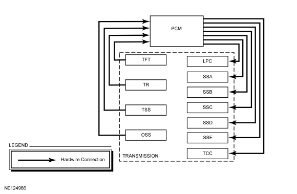
The PCM and its input/output network controls the following operations:
- Shift timing
- Line pressure (shift feel)
The transmission control strategy is separate from the engine control strategy in the PCM , although some of the input signals are shared. When determining the best operating strategy for transmission operation, the PCM uses input information from engine and driver related sensors and switches.
In addition, the PCM receives input signals from transmission related sensors and switches. The PCM uses these signals when determining transmission operating strategy.
Using all of these input signals, the PCM can determine when the time and conditions are right for a shift or when to apply or release the TCC. It also determines the best line pressure to optimize shift engagement feel. To accomplish this, the PCM uses output solenoids to control transmission operation.
Network Message Chart
Communication Message Chart
Component Description
Sensors and Switches
The PCM controls the electronic functions of this transmission. The PCM receives input signals from engine and transmission sensors and uses these inputs to control line pressure, shift time, TCC and shift solenoids.
Solenoid Body
The solenoid body contains 7 solenoids: 5 shift solenoids ( SSA , SSB , SSC , SSD and SSE ), 1 TCC solenoid and 1 LPC solenoid. The TFT sensor is located in the solenoid body. The solenoid body is serviced as an assembly.
The solenoid body has a unique strategy data file that must be downloaded to the PCM. There is a 7-digit solenoid body identification and a 13-digit solenoid body strategy for each solenoid body. When a new solenoid body or transmission is installed, the scan tool must be used to get the solenoid body strategy data file and download it into the PCM.
If the PCM is replaced and the PCM data cannot be inhaled or exhaled, the solenoid body identification and solenoid body strategy must be downloaded into the PCM.
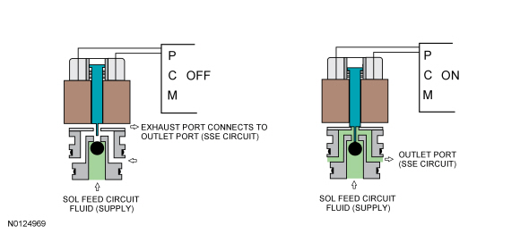
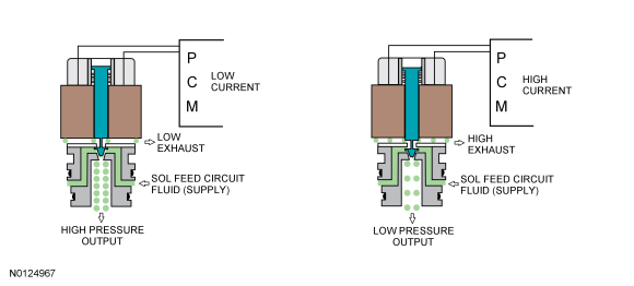
This transmission uses 3 types of solenoids: On/Off, normally low and normally high. On/Off solenoids open or close hydraulic passages based on the voltage signal it receives. Normally low solenoids provide hydraulic pressure proportional to supplied current. A normally low solenoid will not provide pressure without current, while it will supply high pressure with high current. Normally high solenoids provide pressure inversely proportional to supplied current. Normally high solenoids provide full output of pressure with no current and very low pressure with high current.
ON/OFF Solenoids
Normally Low Solenoids
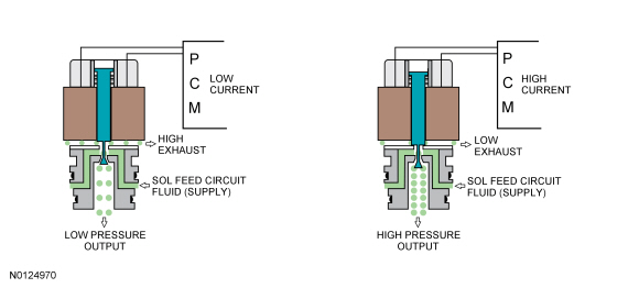
Normally High Solenoids
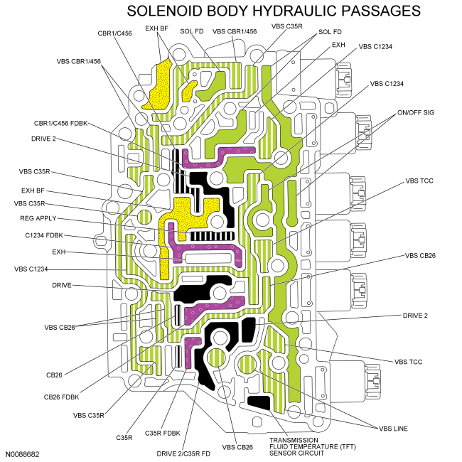
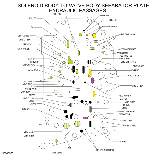
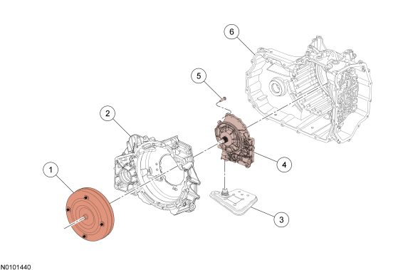
Hydraulic System
Component Location
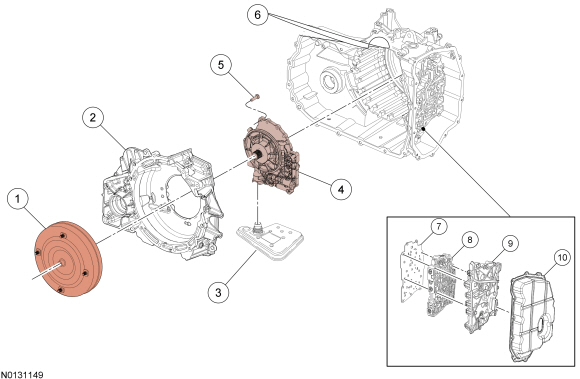
- Torque converter
- Torque converter housing
- Transmission fluid filter
- Pump assembly
- Pump-to-torque converter housing bolt
- Transmission case
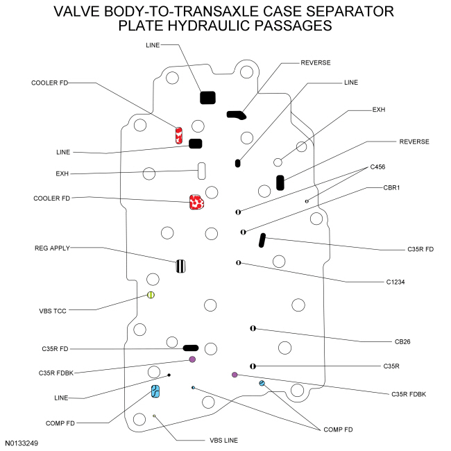
- Main control-to-transmission case seperator plate
- Valve body
- Solenoid body assembly
- Main control cover
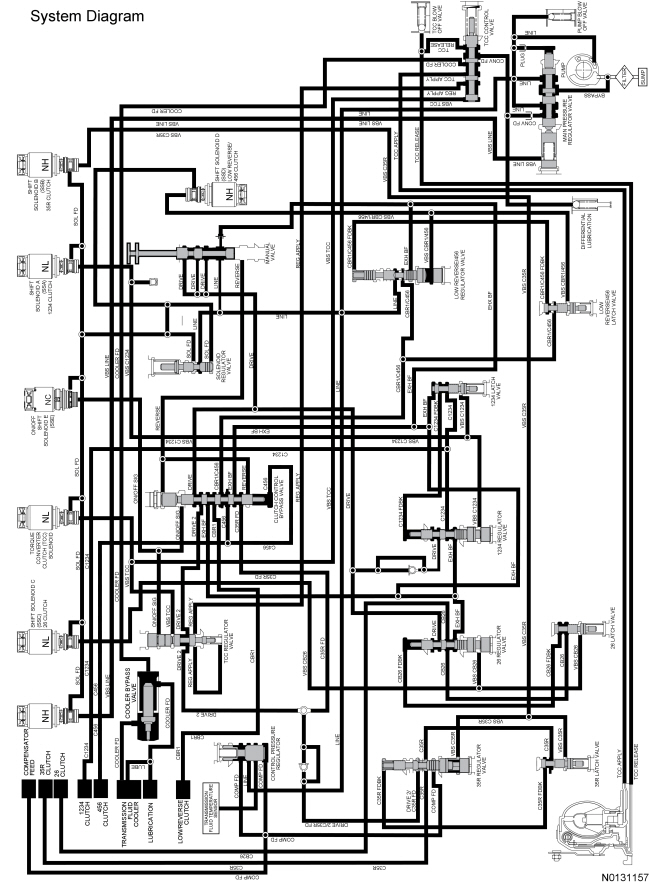
System Operation
System Diagram
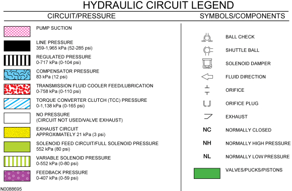
Hydraulic Circuit Legend
Hydraulic Circuit Identification Chart
Component Description
Transmission Fluid Filter
The transmission fluid in the sump area at the bottom of the transmission case flows through a transmission fluid filter to the pump assembly. The pump is bolted to the torque converter housing and is driven by the torque converter hub.
Fluid Pump and Transmission Fluid Filter Components
- Torque converter
- Torque converter housing
- Transmission fluid filter
- Pump assembly
- Pump-to-torque converter housing bolt
- Transmission case
Main Control
The hydraulic system has a main control assembly. The main control assembly consists of a valve body and a solenoid body. Both the valve body and the solenoid body contain hydraulic shift valves. The solenoid body contains the shift solenoids that control the hydraulic valves. The solenoid body can be serviced as an assembly with the solenoids or the solenoids can be serviced individually. The solenoid body is controlled by the PCM. The PCM has software stored in it specific to the solenoid body currently in the transmission, called the solenoid body strategy. A new solenoid body strategy must be downloaded into the PCM anytime a new solenoid body is installed.
The pump assembly contains the main pressure regulator valve assembly and the TCC control valve assembly.
Main Control Components
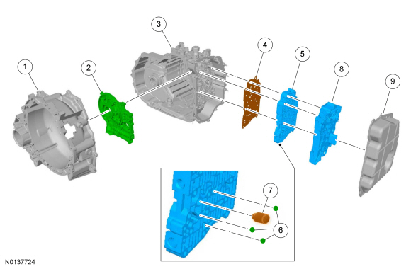
- Torque converter housing
- Pump assembly
- Transmission case
- Main control-to-transmission case separator plate
- Valve body
- Check balls
- Solenoid damper ( SSA )
- Solenoid body assembly
- Main control cover
Main Control Valve Body
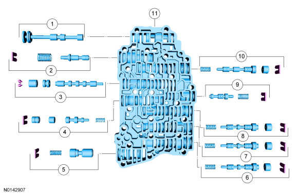
- Manual valve
- Solenoid pressure regulator valve assembly
- Clutch bypass valve
- TCC regulator valve
- Control pressure regulator
- Direct (3, 5, R) clutch regulator valve
- Intermediate (2, 6) clutch regulator valve
- Forward (1, 2, 3, 4) clutch regulator valve
- Forward (1, 2, 3, 4) clutch latch valve
- Low reverse/overdrive (4, 5, 6) clutch regulator valve
- Valve body
Solenoid Body
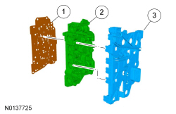
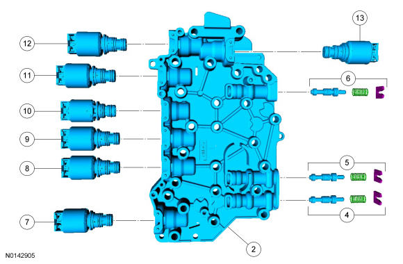
- Main control valve body-to-solenoid body separator plate
- Solenoid body
- Solenoid body leadframe
- Direct (3, 5, R) clutch latch valve
- Intermediate (2, 6) clutch latch valve
- Low reverse/overdrive (4, 5, 6) clutch latch valve
- LPC solenoid
- SSC
- TCC
- ON/OFF solenoid
- SSA
- SSB
- SSD
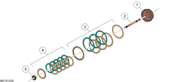
Multi-Plate Clutch
Multi-plate clutches are clutches that consist of multiple friction and steel clutch discs that when pressure is applied, either drive or hold (brake) components of the planetary gearset. This transmission has 5 multi-plate clutches:
- Forward (1,2,3,4)
- Direct (3,5,R)
- Intermediate (2,6)
- Overdrive (4,5,6)
- Low/reverse
Both the direct (3,5,R) and the overdrive (4,5,6) clutches are drive clutches. The direct (3,5,R) clutch drives the rear planetary sun gear and the overdrive (4,5,6) clutch drives the rear planetary carrier. The forward (1,2,3.4), intermediate (2,6) and the low/reverse clutches are brake clutches. The forward (1,2,3,4) clutch holds the front sun gear, the intermediate (2,6) clutch holds the rear sun gear and the low/reverse clutch holds the rear planetary carrier.
Clutches; overdrive (4,5,6) and direct (3,5,R) are balanced in terms of dynamic pressure. That is, their pistons are exposed to the transmission fluid flow on both sides to prevent pressure buildup in the clutch as speed increases. This dynamic pressure equalization process is achieved by a baffle plate and pressure-free transmission fluid supply by a lubricating passage, through which the space between the piston and baffle plate is filled with transmission fluid.
The advantages of this dynamic pressure equalization are:
- reliable clutch engagement and release in all speed ranges.
- improved shift refinement.
External Sealing
The torque converter housing has a lip-type seal that seals the torque converter hub. The pump assembly seals to the torque converter housing with a rubber seal. The manual shaft and halfshafts also use liptype seals.
The torque converter housing is sealed to the transmission case with silicone sealant.
The main control cover is sealed to the transmission case with silicone sealant and seals to the solenoid body with a reusable rubber gasket. The TSS sensor is sealed to the transmission case with an O-ring seal.
The line pressure tap plug and transmission fluid drain plug have pipe threads and seal when tightened to specification.
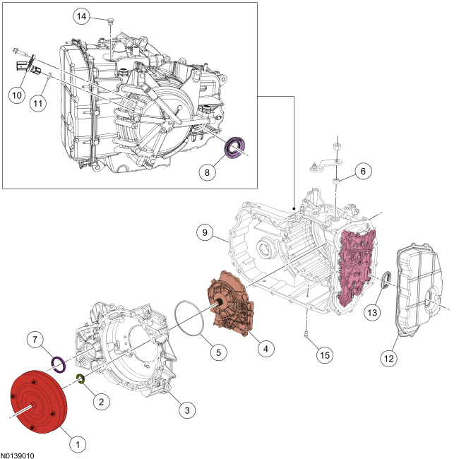
- Torque converter
- Torque converter hub seal
- Torque converter housing
- Pump assembly
- Pump assembly-to-torque converter housing O-ring seal
- Manual control shaft seal
- RH halfshaft seal
- LH halfshaft seal
- Transmission case
- TSS sensor
- TSS sensor O-ring seal
- Main control cover
- Main control-to-cover seal
- Line pressure tap plug
- Drain plug
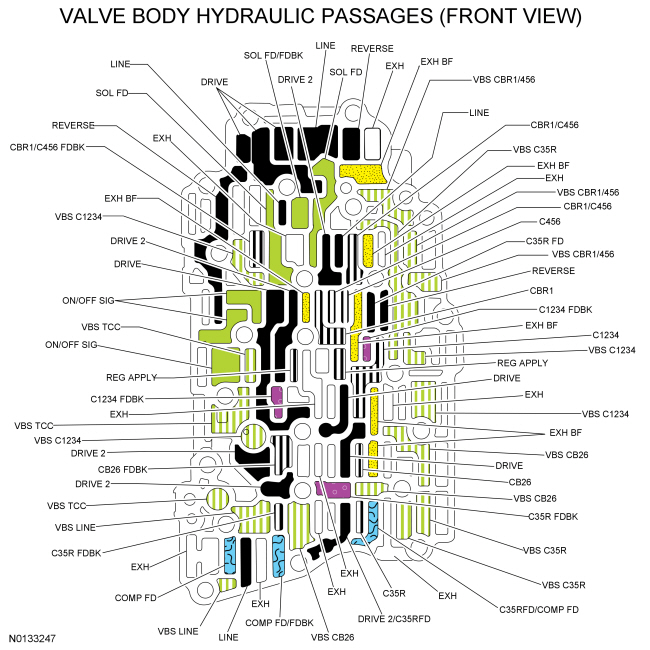
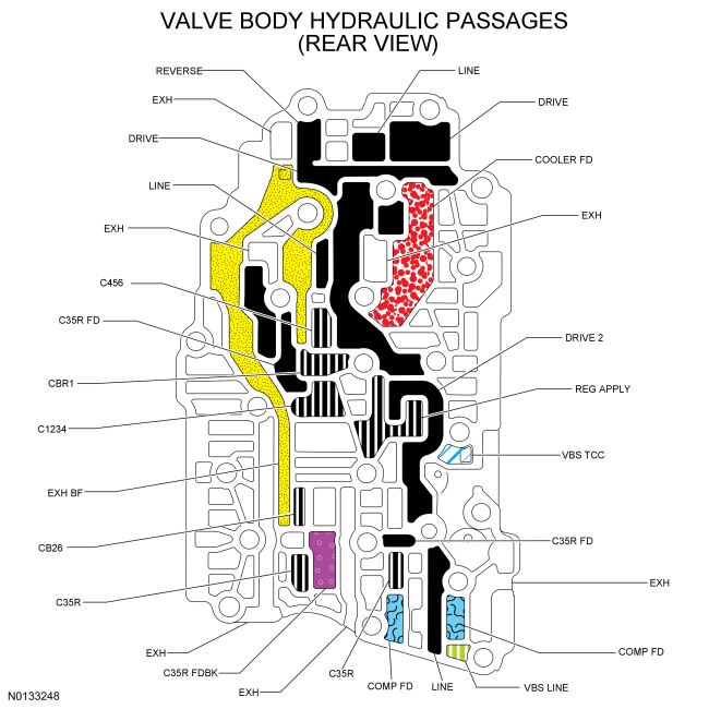
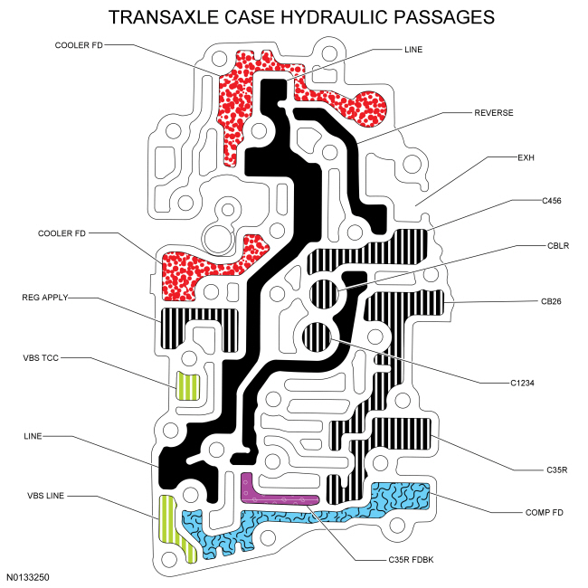
Hydraulic Circuits Legend

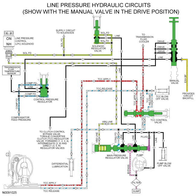
Line Pressure Hydraulic Circuits
Line pressure is controlled by the LPC solenoid, which is controlled by the PCM. This effects shift feel and apply component operation.
When the engine is running, the pump supplies pressure to the main pressure regulator valve, which is controlled by the LPC solenoid. The main pressure regulator valve controls the line pressure to the LINE circuit which supplies the manual valve solenoid regulator valve and the control pressure regulator valve.
When the manual valve is in the reverse position, it supplies the clutch control bypass valve with line pressure to position it to supply line pressure to the direct (3, 5, R) regulator valve and regulated line pressure to the low/reverse clutch to apply the clutch.
When the manual valve is in the DRIVE or LOW positions, it directs line pressure from the LINE circuit to the DRIVE circuit to supply line pressure to the:
- Clutch control bypass valve
- Forward (1, 2, 3, 4) regulator valve
- Intermediate (2, 6) regulator valve
- TCC regulator valve
- Direct (3, 5, R) clutch regulator valve
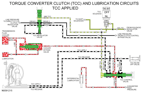
TCC and Lubrication Hydraulic Circuits
Pressure for TCC release is supplied by the main pressure regulator valve to the TCC control valve through the CONV FD circuit. The CONV FD circuit also supplies lubrication for the differential. When the TCC is released, the TCC control valve is positioned by the TCC solenoid to direct CONV FD pressure to the TCC RELEASE circuit to release the TCC. TCC RELEASE pressure returns to the TCC control valve through the TCC APPLY circuit. The position of the TCC control valve opens the TCC APPLY circuit to the COOLER FD circuit which allows the transmission fluid returned from the torque converter to cycle through the thermal bypass valve circuit when the TFT is below 80ÂşC-93ÂşC (176ÂşF-200ÂşF) or the transmission fluid cooler when the temperature is above 80ÂşC-93ÂşC (176ÂşF-200ÂşF).
Return transmission fluid from the thermal bypass valve or the transmission fluid cooler supplies transmission lubrication through the LUBE circuit which runs through the input shaft.
For lubrication passage location and description, refer to Hydraulic Circuit Identification Chart in this section.
The position of the TCC control valve is controlled by pressure from the TCC solenoid through the VBS TCC circuit. The TCC solenoid is controlled by the PCM.
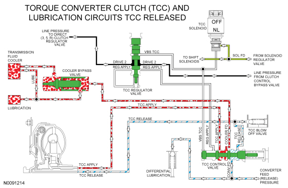
When the TCC clutch is applied, the TCC solenoid applies pressure to the TCC control and regulator valves to position the valves to apply the TCC clutch. Regulated line pressure is supplied to the TCC control valve through the REG APPLY circuit by the TCC regulator valve. The TCC control valve directs the regulated line pressure from the REG APPLY circuit to the TCC APPLY circuit to apply the TCC. The TCC control valve blocks the TCC RELEASE circuit to maintain pressure in the TCC APPLY circuit. The TCC control valve directs the CONV FD circuit to the COOLER FD circuit to allow the transmission fluid to flow through the thermal bypass valve or the transmission fluid cooler to the LUBE circuit to lubricate the transmission.
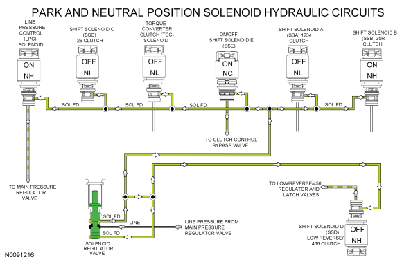
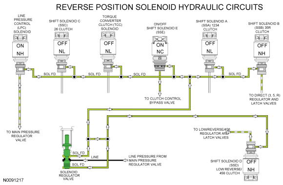
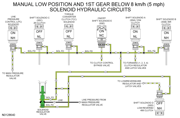
Solenoid Hydraulic Circuits
Line pressure from the main pressure regulator valve is directed to the individual shift, TCC and LPC solenoids by the solenoid regulator valve through the SOL FD circuit. The solenoids, controlled by the PCM, direct the fluid to the valves that they control.
The LPC solenoid applies varying pressure to the main pressure regulator valve to control line pressure.
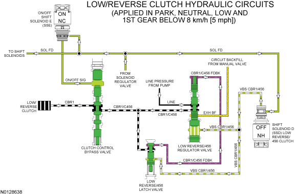
In the PARK and NEUTRAL positions, SSD applies varying pressure to the low reverse/456 regulator and latch valves through the VBS CBR1/456 hydraulic circuit to position the valves to apply the low/reverse clutch. ON/OFF SSE directs pressure to the clutch control bypass valve to position the valve to direct regulated line pressure from the low reverse/456 regulator valve to the low/reverse clutch.
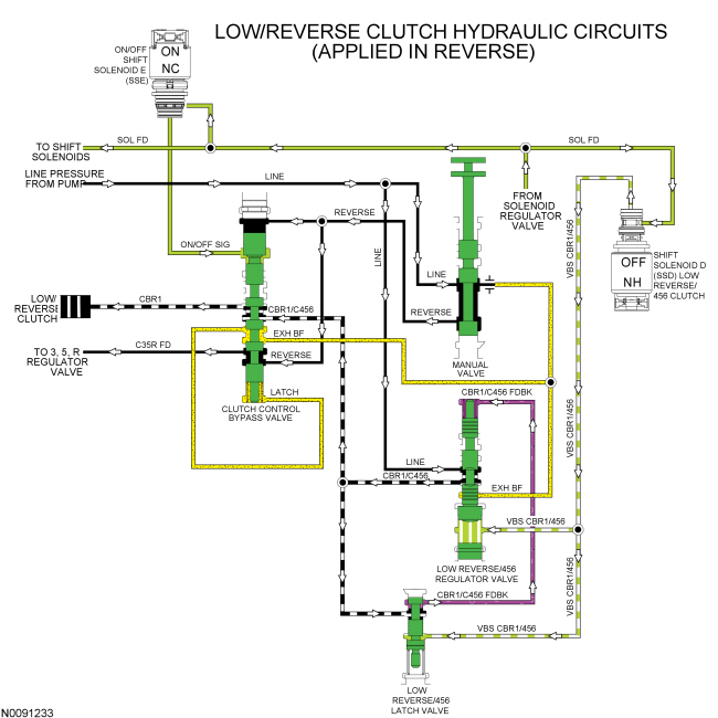
In the REVERSE position, SSD applies varying pressure to the low reverse/456 regulator and latch valves through the VBS CBR1/456 hydraulic circuit to position the valves to apply the low/reverse clutch. ON/OFF SSE directs pressure to the clutch control bypass valve to position the valve to direct regulated line pressure from the low reverse/456 regulator valve to the low/reverse clutch. The clutch control bypass valve also directs line pressure from the REVERSE circuit to the 35R regulator valve through the C35R FD and DRIVE 2/C35R FD circuits. SSB directs varying pressure to the 35R regulator and latch valves through the VBS C35R hydraulic circuit to apply the direct (3, 5, R) clutch.
In 1st gear, SSA applies varying pressure to the 1234 clutch regulator and latch valves through the VBS C1234 hydraulic circuit to apply the forward (1, 2, 3, 4) clutch.
When vehicle speed is below 8 km/h (5 mph), or the selector lever is in the manual low position, SSD applies varying pressure to the low reverse/456 regulator and latch valves through the VBS CBR1/456 hydraulic circuit to position the valves to apply the low/reverse clutch. ON/OFF SSE directs pressure to the clutch control bypass valve to position the valve to direct regulated line pressure from the low reverse/456 regulator valve to the low/reverse clutch. As vehicle speed increases above 8 km/h (5 mph) in 1st gear, SSD removes pressure from the low reverse/456 regulator and latch valves and SSE removes pressure from the clutch control bypass valve to release the low/reverse clutch.
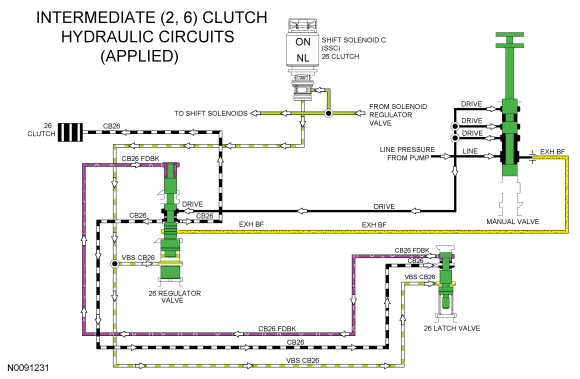
In 2nd gear, the forward (1, 2, 3, 4) clutch remains applied. SSC applies varying pressure to the 26 regulator and latch valves through the VBS CB26 hydraulic circuit to apply the intermediate (2, 6) clutch.
In 3rd gear, the forward (1, 2, 3, 4) clutch remains applied. SSC releases pressure to the 26 regulator and latch valves to release the intermediate (2, 6) clutch. SSB directs pressure to the 35R regulator and latch valves through the VBS CB26 hydraulic circuit to apply the direct (3, 5, R) clutch.
In 4th gear, the forward (1, 2, 3, 4) clutch remains applied. SSB releases pressure to the 35R regulator and latch valves. SSD directs pressure to the low reverse/456 regulator and latch valves through the VBS CBR1/456 hydraulic circuit. With SSE released, the clutch control bypass valve directs the regulated line pressure from the low reverse/456 regulator valve to the O/D (4, 5, 6) clutch to apply the clutch.
In 5th gear, the O/D (4, 5, 6) clutch remains applied. SSA releases pressure to the 1234 regulator and latch valves to release the forward (1, 2, 3, 4) clutch. SSB directs pressure to the 35R regulator and latch valves through the VBS C35R hydraulic circuit to apply the direct (3, 5, R) clutch.
In 6th gear, the O/D (4, 5, 6) clutch remains applied. SSB releases pressure to the 35R regulator and latch valves. SSC applies varying pressure to the 26 clutch regulator and latch valves through the VBS CB26 hydraulic circuit to apply the intermediate (2, 6) clutch.
The TCC can be applied in 4th, 5th or 6th gear. To apply the TCC , the TCC solenoid applies pressure to the TCC regulator valve and the TCC control valve to position the valves to apply the clutch.
During a mechanical, hydraulic or electrical failure with the manual lever in the DRIVE position, the transmission defaults to 5th gear. When the transmission is in 5th gear failsafe, the PCM does not control the shift solenoids and they default to their normal state (maximum pressure, minimum pressure, on or off). The LPC solenoid defaults to maximum pressure, SSA defaults to minimum pressure, SSB defaults to maximum pressure, SSC defaults to minimum pressure, SSD defaults to maximum pressure and the TCC solenoid defaults to minimum pressure.
With SSB applying maximum pressure to the direct (3, 5, R) regulator and latch valves, the direct (3, 5, R) clutch is applied. With SSD applying maximum pressure to the low reverse/456 regulator and latch valves with SSE in the OFF position, the O/D (4, 5, 6) clutch is applied, providing 5th gear.
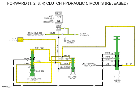
Forward (1, 2, 3, 4) Clutch Hydraulic Circuits
Line pressure is supplied to the 1234 regulator valve by the manual valve in the DRIVE and LOW position. To apply the forward (1, 2, 3, 4) clutch, SSA supplies varying solenoid pressure to the 1234 regulator and latch valves. As the regulator valve moves, it supplies the forward (1, 2, 3, 4) clutch and 1234 latch valve with regulated line pressure through the C1234 circuit. The 1234 latch valve directs the regulated line pressure to the opposite side of the 1234 regulator valve through the C1234 FDBK circuit for gradual forward (1, 2, 3, 4) clutch engagement. The forward (1, 2, 3, 4) clutch is applied in 1st, 2nd, 3rd and 4th gears and manual LOW position.
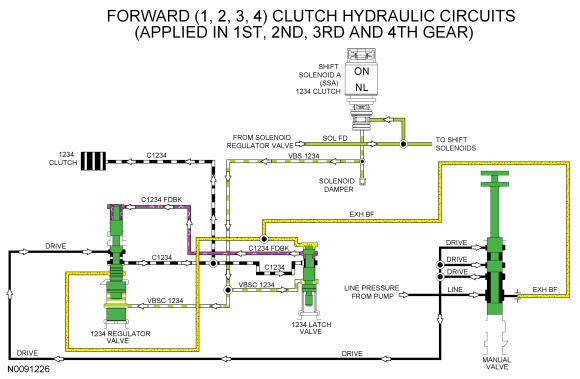
When the forward (1, 2, 3, 4) clutch is released in 5th and 6th gears, solenoid pressure from SSA is removed from the 1234 regulator and latch valves which positions the valves to block line pressure and release the forward (1, 2, 3, 4) clutch. When the forward (1, 2, 3, 4) clutch is released in the PARK, REVERSE or NEUTRAL position, line pressure is not supplied to the forward (1, 2, 3, 4) regulator valve.
In the released position, exhaust backfill supplied to the 1234 regulator and latch valves by the manual valve through the EXH BF circuit is directed to the forward (1, 2, 3, 4) clutch to fill the unused circuits with unpressurized transmission fluid.
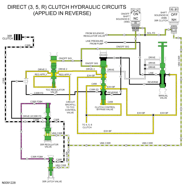
Direct (3, 5, R) Clutch Hydraulic Circuits
When the direct (3, 5, R) clutch is applied in the REVERSE position, line pressure from the manual valve is directed to the clutch control bypass valve through the REVERSE circuit. Line pressure in the REVERSE circuit positions the clutch control bypass valve and supplies line pressure to apply the direct (3, 5, R) clutch. Line pressure from the clutch control bypass valve is supplied to the 35R regulator valve through the C35R FD circuit, DRIVE 2/C35R FD shuttle ball and DRIVE 2/C35R FD circuit.
To apply the direct (3, 5, R) clutch, SSB applies varying solenoid pressure to the 35R regulator and latch valves. As the regulator valve moves, it supplies the direct (3, 5, R) clutch and 35R latch valve with regulated line pressure through the C35R circuit. The 35R latch valve directs the regulated line pressure to the opposite side of the 35R regulator valve through the C35R FDBK circuit for gradual direct (3, 5, R) clutch engagement.
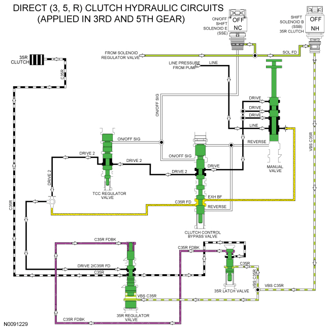
When the direct (3, 5, R) clutch is applied in 3rd and 5th gear, line pressure from the pump is directed to the clutch control bypass valve by the manual valve through the DRIVE hydraulic circuit. The clutch control bypass valve directs the pressure to the 35R regulator valve through the TCC regulator valve, DRIVE 2 circuit, DRIVE 2/C35R FD shuttle ball and DRIVE 2/C35R FD circuit.
To apply the direct (3, 5, R) clutch, SSB applies varying solenoid pressure to the 35R regulator and latch valves. As the 35R regulator valve moves, it supplies the direct (3, 5, R) clutch and 35R latch valve with regulated line pressure through the C35R circuit. The 35R latch valve directs the regulated line pressure to the opposite side of the regulator valve through the C35R FDBK circuit for gradual direct (3, 5, R) clutch engagement.
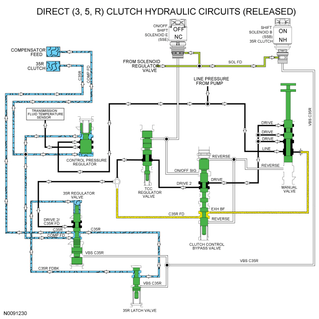
When the direct (3, 5, R) clutch is released, solenoid pressure from SSB is removed from the 35R regulator and latch valves which positions the valves to block line pressure and release the direct (3, 5, R) clutch. When the direct (3, 5, R) clutch is released in the PARK or NEUTRAL position, line pressure is not supplied to the 35R regulator valve.
Compensator feed pressure is supplied to the 35R regulator valve from the control pressure regulator through the COMP FD circuit and is supplied to the opposite side of the direct (3, 5, R) and O/D (4, 5, 6) clutch pistons to keep the clutches from centrifugally applying. COMP FD pressure is only about 83 kPa (12 psi) and is applied through all gears. When the direct (3, 5, R) clutch is released, COMP FD is applied by the 35R regulator valve to the direct (3, 5, R) clutch to fill the unused circuits.
Intermediate (2, 6) Clutch Hydraulic Circuits
Line pressure is supplied to the 26 regulator valve by the manual valve in the DRIVE and LOW positions. To apply the intermediate (2, 6) clutch, SSC supplies varying solenoid pressure to the 26 regulator and latch valves. As the 26 regulator valve moves, it supplies the intermediate (2, 6) clutch and 26 latch valve with regulated line pressure through the CB26 circuit. The 26 latch valve directs the regulated line pressure to the opposite side of the 26 regulator valve through the CB26 FDBK circuit for gradual intermediate (2, 6) clutch engagement. The intermediate (2, 6) clutch is applied in 2nd and 6th gears.
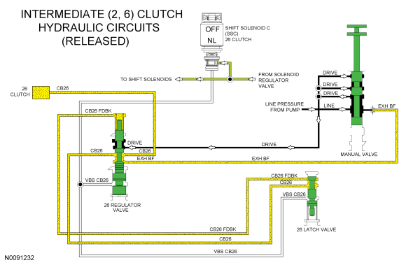
When the intermediate (2, 6) clutch is released in 1st, 3rd, 4th and 5th gears and manual LOW position, solenoid pressure from SSC is removed from the 26 regulator and latch valves which positions the valves to block line pressure and release the intermediate (2, 6) clutch. When the intermediate (2, 6) clutch is released in the PARK, REVERSE or NEUTRAL position, line pressure is not supplied to the 26 regulator valve.
In the released position, exhaust backfill supplied to the 26 clutch regulator valve by the manual valve through the EXH BF circuit is directed to the intermediate (2, 6) clutch and 26 latch valve to fill the unused circuits with unpressurized transmission fluid.
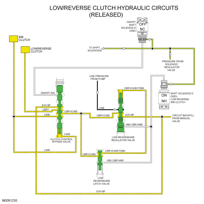
Low/Reverse Clutch Hydraulic Circuits
Line pressure is supplied to the low reverse/456 regulator valve by the pump in every gear and manual lever position. To apply the low/reverse clutch, SSD supplies varying solenoid pressure to the low reverse/456 regulator and latch valves. As the low reverse/456 regulator valve moves, it supplies the clutch control bypass valve and low reverse/456 latch valve with regulated line pressure through the CBR1/C456 circuit. The low reverse/456 latch valve directs the regulated line pressure to the opposite side of the 456 regulator valve through the CBR1/C456 FDBK circuit for gradual low reverse/456 clutch engagement. The low/reverse clutch is applied in PARK, REVERSE, NEUTRAL, 1st gear below 8 km/h (5 mph) and manual LOW position.
In REVERSE, both solenoid pressure from ON/OFF SSE and line pressure from the manual valve in the REVERSE circuit apply pressure to the clutch control bypass valve to position it for low/reverse clutch application. Regulated line pressure from the CBR1/C456 circuit is directed to the low/reverse clutch by the clutch control bypass valve through the CBR1 circuit to apply the low/reverse clutch.
When the low/reverse clutch is applied in PARK, NEUTRAL, LOW or 1st gear below 8 km/h (5 mph), only pressure from ON/OFF SSE , positions the clutch control bypass valve. Line pressure from the REVERSE circuit is not supplied by the manual valve.
When the low/reverse clutch is released in 1st gear above 8 km/h (5 mph), 2nd and 3rd gears, solenoid pressure from SSD is removed from the low reverse/456 regulator and latch valves which positions the valves to block line pressure and release the low/reverse clutch. Solenoid pressure from SSE is removed from the clutch control bypass valve to position it to apply the O/D (4, 5, 6) clutch.
When the low/reverse clutch is released in 1st gear above 8 km/h (5 mph), 2nd and 3rd gears, exhaust backfill supplied to the low reverse/456 clutch regulator valve and the clutch control bypass valve by the manual valve through the EXH BF circuit is directed to the low reverse/456 latch valve, low/reverse clutch and O/D (4, 5, 6) clutch to fill the unused circuits with unpressurized transmission fluid.
When the low/reverse clutch is released in 4th, 5th and 6th gears, the low reverse/456 regulator valve supplies regulated pressure to the clutch control bypass valve through the CBR1/C456 circuit. With ON/OFF SSE in the OFF position, the regulated pressure is directed to the O/D (4, 5, 6) clutch.
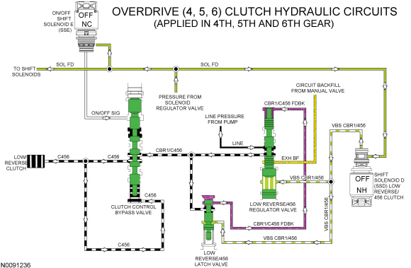
Overdrive (4, 5, 6) Clutch Hydraulic Circuits
Line pressure is supplied to the low reverse/456 regulator valve by the pump in every gear and manual lever position. To apply the low/reverse clutch, SSD supplies varying solenoid pressure to the low reverse/456 regulator and latch valves. As the regulator valve moves, it supplies the clutch control bypass valve and low reverse/456 latch valve with regulated line pressure through the CBR1/C456 circuit. The low reverse/456 latch valve directs the regulated line pressure to the opposite side of the low reverse/456 regulator valve through the CBR1/C456 FDBK circuit for gradual O/D (4, 5, 6) clutch engagement.
To apply the O/D (4, 5, 6) clutch, the position of the clutch control bypass valve allows the regulated line pressure in the CBR1/C456 circuit to supply the C456 circuit, applying the O/D (4, 5, 6) clutch. Clutch control bypass valve latch pressure is supplied by the C456 circuit. The O/D (4, 5, 6) clutch is applied in 4th, 5th and 6th gears.
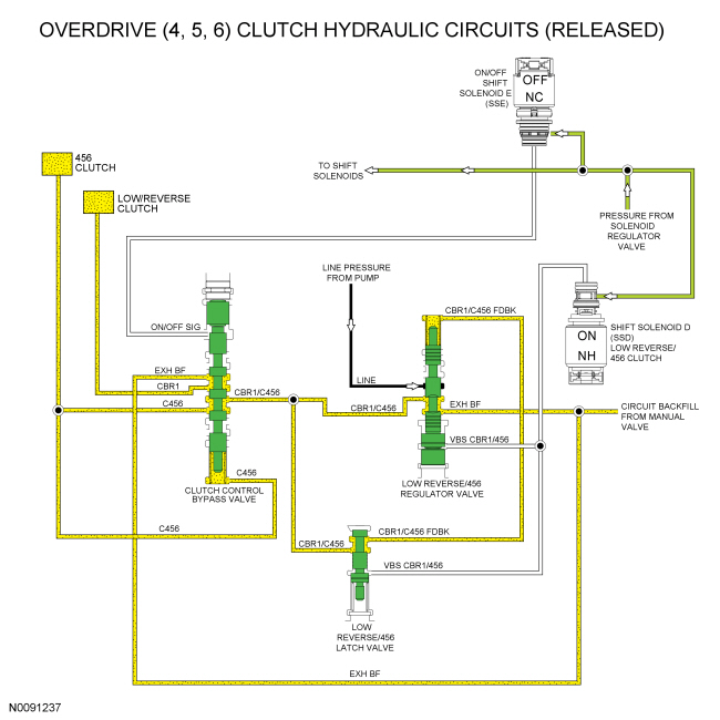
When the O/D (4, 5, 6) clutch is released in 1st gear above 8 km/h (5 mph), 2nd and 3rd gears, solenoid pressure from SSD is removed from the low reverse/456 regulator and latch valves which positions the valves to block line pressure and release the O/D (4, 5, 6) clutch.
When the O/D (4, 5, 6) clutch is released in 1st gear above 8 km/h (5 mph), 2nd and 3rd gears, exhaust backfill supplied to the low reverse/456 clutch regulator valve and the clutch control bypass valve by the manual valve through the EXH BF circuit is directed to the low reverses latch valve, low/reverse clutch and O/D (4, 5, 6) clutch to fill the unused circuits with unpressurized transmission fluid.
When the O/D (4, 5, 6) clutch is released in PARK, REVERSE, NEUTRAL and 1st gear below 8 km/h (5 mph), the low reverse/456 regulator valve supplies regulated pressure to the clutch control bypass valve through the CBR1/C456 circuit. With ON/OFF SSE in the ON position, the regulated pressure is directed to the low/reverse clutch.
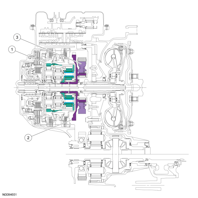
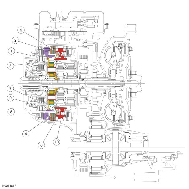
Mechanical System
Component Location
- Forward clutch (clutch brake 1, 2, 3, 4)
- Low/reverse clutch (clutch brake low/reverse)
- Intermediate clutch (clutch brake 2, 6)
- Low OWC
- Direct clutch (drive clutch 3, 5, R)
- O/D clutch (drive clutch 4, 5, 6)
- Rear planetary assembly
- Center planetary assembly
- Front planetary assembly
- Final drive carrier and differential assembly
- Drive chain driven sprocket
- Input shaft assembly and direct/overdrive clutch hub
- Drive chain drive sprocket
- Drive chain
- Park gear
- Park pawl
System Operation
System Diagram
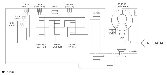
Component Description
Planetary Gearset
This transmission has 3 planetary gearsets to provide operation in reverse and 6 forward speeds.
The gearsets are comprised of the following components:
- Front planetary sun gear (part of the front sun gear and shell assembly)
- Front planetary carrier
- Front planetary ring gear
- Center planetary sun gear
- Center planetary carrier
- Center planetary ring gear
- Rear planetary ring gear
- Rear planetary carrier
- Rear planetary sun gear and shell assembly
The front planetary sun gear is splined to the forward (1, 2, 3, 4) clutch and is held stationary in 1st, 2nd, 3rd and 4th gears.
The front planetary carrier is splined to the rear planetary ring gear and transfers power from the rear planetary gearset to the front planetary gearset in 2nd, 3rd, 5th and 6th gears and reverse. The front planetary carrier is splined to the drive chain drive sprocket. The front planetary carrier is the output component for the planetary gearset.
The front planetary ring gear is splined to the center planetary carrier and transfers power from the center planetary gearset to the front planetary gearset in 1st, 2nd, 3rd and 4th gears.
The center planetary sun gear is splined to the input shaft and is used as input to the planetary gearsets in 1st, 2nd, 3rd and 4th gear.
The center planetary ring gear is splined to the rear planetary carrier and transfers power from the center planetary gearset to the rear planetary gearset in 3rd gear, from the rear planetary gearset to the center planetary gearset in 4th gear and is held stationary by the low OWC and low/reverse clutch in 1st gear and reverse.
The rear planetary carrier is splined to the O/D (4, 5, 6) clutch hub and transfers power from the input shaft to the rear planetary carrier in 4th, 5th and 6th gears.
The rear planetary sun gear and shell assembly is splined to both the intermediate (2, 6) clutch and the direct (3, 5, R) clutch. The rear planetary sun gear and shell assembly is held stationary by the intermediate (2, 6) clutch in 2nd and 6th gear and is driven by the direct (3, 5, R) clutch in 3rd and 5th gears and reverse.
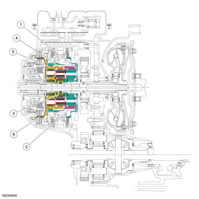
Planetary Gearset Cutaway View
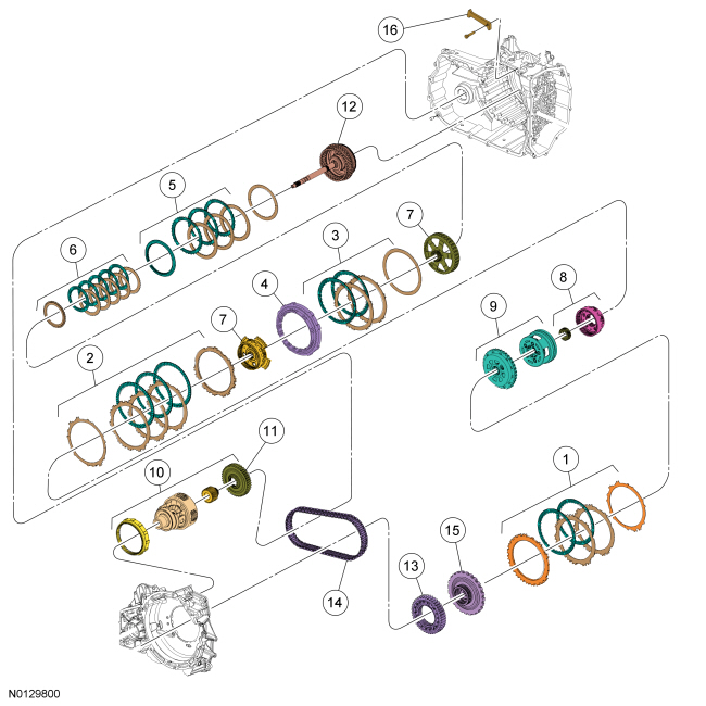
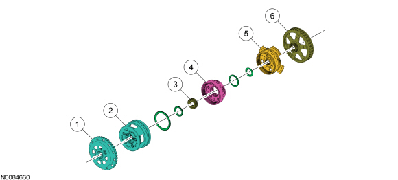
Planetary Gearset Exploded View
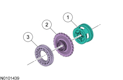
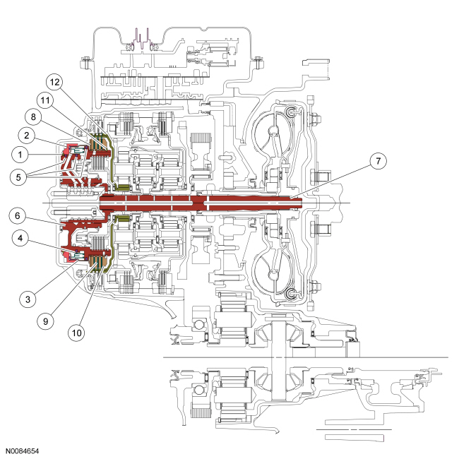
Input Shaft
The input shaft is part of the direct/ O/D clutch assembly and is splined to the torque converter turbine and the center planetary sun gear. The input shaft transfers power from the torque converter to the rear planetary gearset through the center planetary sun gear and the direct (3, 5, R) and O/D (4, 5, 6) clutches.
Input Shaft Cutaway View
Input Shaft Exploded View
Front Planetary Carrier Hub (Output Hub)
The front planetary carrier hub/park gear is splined to the front planetary carrier and the drive chain drive sprocket. This allows torque to be transferred from the planetary gearset to the final drive gearset.
Front Planetary Carrier Hub Cutaway View
Front Planetary Carrier Hub Exploded View
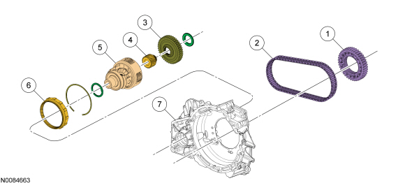
Final Drive Chain, Sprockets and Planetary Gearset
The final drive consists of a drive chain and sprockets and a planetary gearset and differential assembly. The drive chain and sprockets transfer torque from the front planetary carrier hub to the differential assembly that has a planetary gearset integrated into it for final drive torque multiplication.
The final drive consists of the following components:
- Drive sprocket
- Drive chain
- Driven sprocket
- Final drive sun gear
- Final drive ring gear
- Final drive planetary carrier and differential assembly
Final Drive Component Cutaway View
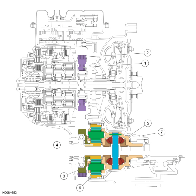
Final Drive Component Exploded View
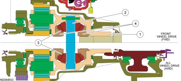
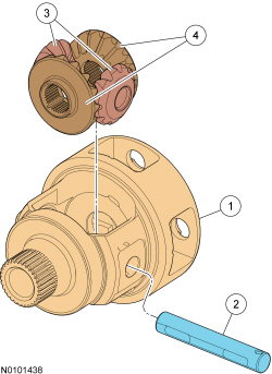
Differential
The differential allows the halfshafts and wheels to rotate at different speeds during cornering and transfers power to the PTU for AWD vehicles.
The differential assembly consists of the following components:
- Differential case (part of the final drive carrier)
- Two pinion gears supported by a pinion shaft
- Two side gears supported by the differential case and halfshafts
When driving in a straight line, both front wheels rotate at relatively the same speed. This means both side gears are rotating at the same speed, as well, while both pinion gears revolve (but do not rotate) with the side gears. During cornering, the wheel on the outside of the turn is forced to rotate faster than the wheel on the inside of the turn. Since the side gears must now rotate at different speeds, the pinion gears rotate on the pinion shaft allowing the drive axles to rotate at different speeds while still transferring output torque.
Differential Cutaway View
Differential Exploded View
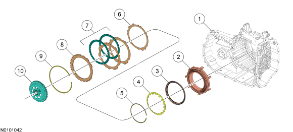
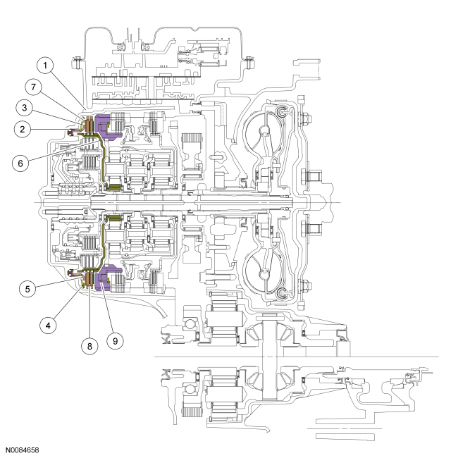
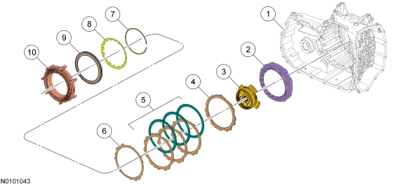
Forward (1, 2, 3, 4) Clutch
The forward clutch is a brake clutch that holds the front sun gear and shell assembly. The forward clutch is applied in 1st, 2nd, 3rd and 4th gears.
Hydraulic pressure from the regulator valve in the valve body pushes the forward clutch piston against the forward clutch pack to apply the clutch. The front sun gear and shell assembly is held stationary to the transmission case as a result of the clutch being applied.
Forward (1, 2, 3, 4) Clutch Cutaway View
Forward (1, 2, 3, 4) Clutch Exploded View
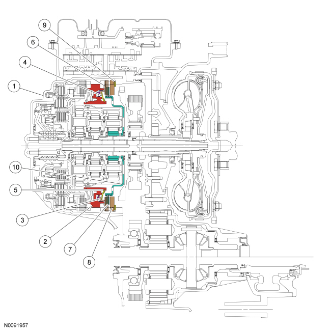
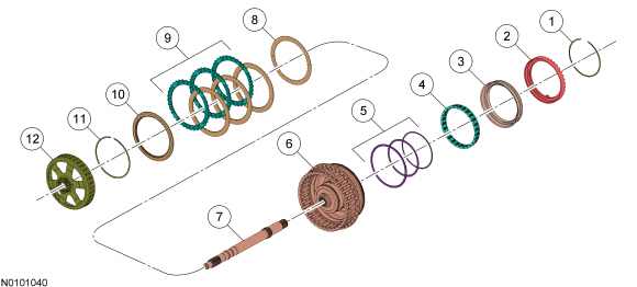
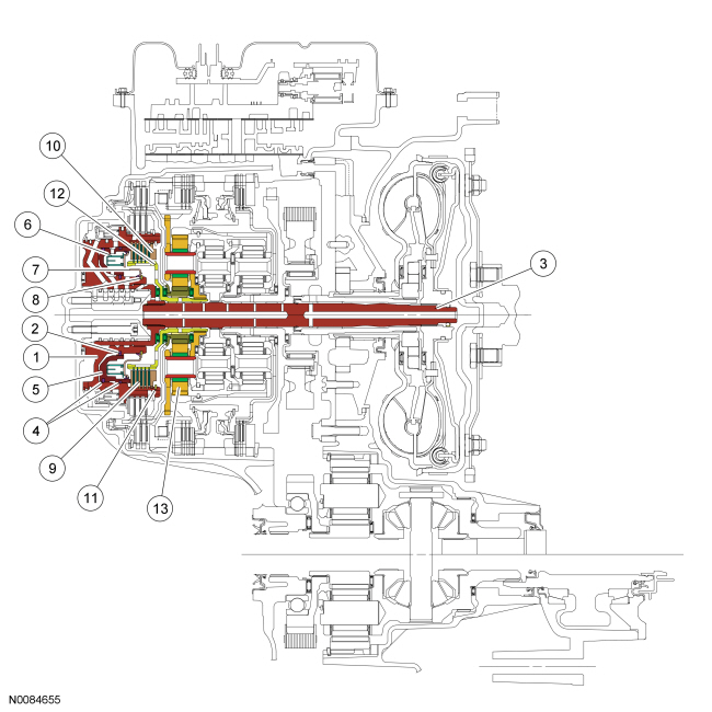
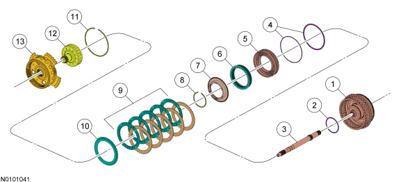
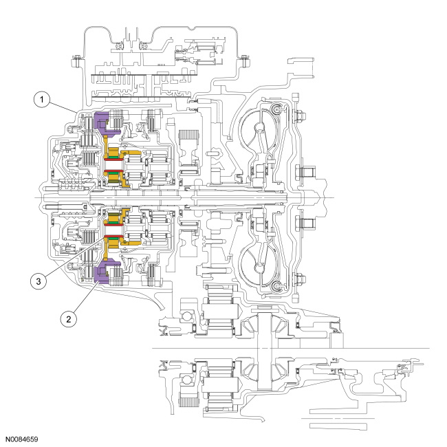
Direct (3, 5, R) Clutch
The direct clutch is a drive clutch that transfers power from the direct/ O/D clutch hub assembly to the rear planetary sun gear and shell assembly. The direct clutch is applied in 3rd and 5th gears and reverse.
Hydraulic pressure from the regulator valve in the valve body pushes the direct clutch piston against the direct clutch pack to apply the clutch. The input shaft and direct/ O/D clutch hub assembly transfers torque to the rear planetary sun gear and shell assembly as a result of the clutch being applied.
Direct (3, 5, R) Clutch Cutaway View
Direct (3, 5, R) Clutch Exploded View
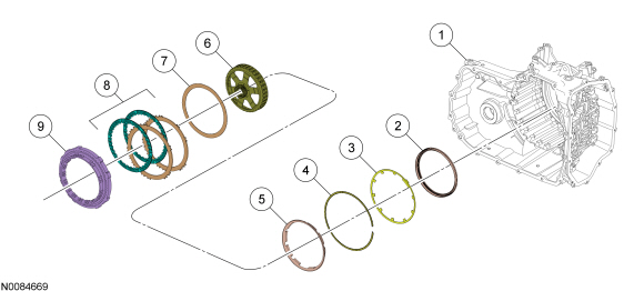
Intermediate (2, 6) Clutch
The intermediate clutch is a brake clutch that holds the rear planetary sun gear and shell assembly. The intermediate clutch is applied in 2nd and 6th gears.
Hydraulic pressure from the regulator valve in the valve body pushes the intermediate clutch piston against the intermediate clutch pack to apply the clutch. The low OWC works as a pressure plate for the intermediate (2, 6) clutch. The rear planetary sun gear and shell assembly is held stationary to the transmission case as a result of the clutch being applied.
Intermediate (2, 6) Clutch Cutaway View
Intermediate (2, 6) Clutch Exploded View
Low - Reverse Clutch
The low/reverse clutch is a brake clutch that holds the low OWC which is splined to the rear planetary carrier. The low/reverse clutch is applied in manual LOW, REVERSE and 1st gear up to 8 km/h (5 mph).
Hydraulic pressure from the regulator valve in the valve body pushes the low/reverse clutch piston against the low/reverse clutch pack to apply the clutch. The rear planetary carrier is held stationary to the transmission case as a result of the clutch being applied.
Low/Reverse Clutch Cutaway View
Low/Reverse Clutch Exploded View
Overdrive Clutch
The O/D clutch is a drive clutch that transfers power from the direct/ O/D clutch hub assembly to the rear planetary carrier. The O/D clutch is applied in 4th, 5th and 6th gears.
Hydraulic pressure from the regulator valve in the valve body pushes the O/D clutch piston against the O/D clutch pack to apply the clutch. The input shaft and direct/ O/D clutch hub assembly transfers torque to the rear planetary carrier as a result of the clutch being applied.
Overdrive (O/D) (4, 5, 6) Clutch Cutaway View
Overdrive (O/D) (4, 5, 6) Clutch Exploded View
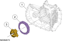
Low One way Clutch
The low OWC is a brake clutch that holds the rear planetary carrier in one direction and allows it to freewheel in the opposite direction which eliminates engine braking in 1st gear when the transmission is in DRIVE. The low OWC is also the pressure plate for the intermediate (2, 6) clutch.
Low OWC Cutaway View
Low OWC Exploded View

 Diagnosis and Testing
Automatic Transmission
Special Tool(s)
Material
DTC Chart
Diagnostics in this manual assume a certain skill level and knowledge of
Ford-specific diagnostic practices. Refer to Diagnostic Method ...
Other materials:
Navigation system
Note: The navigation SD card must be in the SD card slot to operate
the navigation system. If you need a replacement SD card, see your
authorized dealer.
Note: The SD card slot is spring-loaded. To remove the SD card, just
push the card in and release it. Do not attempt to pull the card out to ...
Scheduled Maintenance
GENERAL MAINTENANCE INFORMATION
Why Maintain Your Vehicle?
Carefully following the maintenance schedule helps protect against major
repair expenses resulting from neglect or inadequate maintenance and
may help to increase the value of your vehicle when you sell or trade it.
Keep all receipts ...
Removal and Installation
Frame Members
General Equipment
Material
Front Side Members - Exploded View
NOTE: Right side shown, left side similar.
WARNING: Collision damage repair must conform to the instructions
contained in this workshop manual. Replacement components must be new, genuine
Ford Motor Company ...
