Solenoid Body Identification Procedure
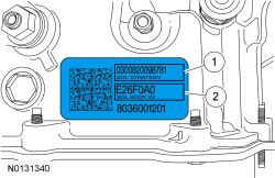
Original Solenoid Body Service Tag
- Using the scan tool, select Powertrain, Transmission and Transmission
Solenoid Body Identification from the toolbox icon and follow the
instructions displayed on the scan tool.
The solenoid body identification screen displays solenoid body identification information:- Solenoid body identification is a 7-digit number
- Solenoid body strategy is a 13-digit number
The next screen displays the current solenoid body identification and strategy data file stored in the PCM. If the solenoid body strategy field is blank, the module contains a partial transmission solenoid body strategy. This is due to a corrupt or missing file at the time the programmable parameters were completed.
- NOTE: The 13-digit solenoid body strategy number consists of only
numbers. Letters are not used.
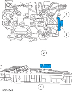
Compare the solenoid body identification and strategy (if available) to the solenoid body original service tag located on top of the transmission case.

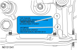
Replacement Solenoid Body Service Tag
- If the solenoid body identification and strategy on the scan tool match
the solenoid body service tag or replacement tag, then the solenoid body
identification and strategy are correct for this transmission and a solenoid
body strategy download is not required. If the solenoid body service tag or
replacement tag is missing or damaged so its not readable or does not match
the identification or strategy on the scan tool, remove the solenoid body
connector and view the solenoid body identification and strategy printed on
the solenoid body connector. If its not readable, remove the main control
cover, REFER to Main Control Cover. The 7-digit identification number and
the 13-digit strategy number are stamped on the solenoid body.

Solenoid Body Identification Tag
- NOTICE: If the solenoid body information does not match the
module information, transmission damage or driveability concerns can occur.
Inspect the solenoid body identification and strategy printed on the solenoid body connector and compare this to the solenoid body service tag on the transmission case. If the solenoid body identification and strategy printed on the solenoid body connector does not match the solenoid body service tag or if the solenoid body identification and strategy printed on the solenoid body connector match the solenoid body service tag on the transmission case but do not match the solenoid body identification and strategy numbers displayed on the scan tool, a solenoid body strategy data download is required.

Solenoid Body Strategy Download
- Using the scan tool, select module Programming and Programmable
Parameters under the toolbox icon and select transmission. Follow the
instructions displayed on the scan tool.
There are fields to enter the solenoid body 7-digit identification and 13-digit strategy recorded from the solenoid body.
- NOTICE: If the solenoid body information is not correct,
transmission damage or driveability concerns can occur.
Enter the solenoid body identification and strategy.
The scan tool verifies the numbers entered are valid and display a message if the information is not valid.
The scan tool will check to verify the file is present on the scan tool. If the file is present, the technician may proceed with downloading the file to the PCM. If the file is not present, the scan tool will need to be connected to the PTS server to download the file onto the scan tool.
- Verify the file is present on the scan tool. If the file is present, go to Step 8. If the file is not present, continue with this procedure.
- Connect the scan tool to the PTS server.
The screen will display a progress bar when connecting to the network.
- Follow the instructions on the network to download the strategy file to
the scan tool.
The screen will display a progress bar when downloading the strategy file to the scan tool and display a message if it is downloaded successfully.
- If the scan tool cannot connect to the PTS server, download the file
from www.motorcraft.com.
If the scan tool cannot download a strategy from the web site, a partial strategy will automatically be downloaded.
- Reconnect the scan tool to the vehicle.
- Follow the instructions displayed on the scan tool.
- If a new solenoid body was installed, compare the 7-digit identification
and the 13-digit strategy fields from the solenoid body to the replacement
solenoid body tag provided with the solenoid body service kit and place it
over the existing identification tag.
The scan tool will automatically download the strategy file or partial strategy file to the PCM and will display a progress bar while downloading. The scan tool will display a message when it is finished downloading the data that states that the file was downloaded successfully.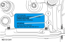

- NOTICE: If a drive cycle is not completed, erratic shifts and
driveability concerns may occur.
Test drive the vehicle. Refer to Solenoid Body Strategy Drive Cycle in this section.
Solenoid Body Strategy Drive Cycle
NOTE: Always drive the vehicle in a safe manner according to driving conditions and obey all traffic laws.
NOTE: The engine and transmission must be at normal operating temperature.
- Bring the transmission to normal operating temperature.
- With the engine running and the brake applied, move the selector lever through the gears in the following order, pausing in each gear for 4 seconds: N, R, N, D, R, D, N. Repeat this pattern 2 times. If any engagements feel soft or harsh, repeat this procedure.
- Drive the vehicle and accelerate at a moderate throttle so that the upshifts occur at 2,000 rpm up to 80 km/h (50 mph) and brake moderately to a stop. Repeat this pattern 2 times.
- Drive the vehicle and accelerate at a moderate throttle so the upshifts occur at 3,000 rpm up to 80 km/h (50 mph) and brake moderately to a stop. Repeat this pattern 2 times.
- With the engine running and the brake applied, move the selector lever through the gears in the following order, pausing in each gear for 4 seconds: N, R, N, D, R, D, N. Repeat this pattern 2 times.
- From a stop, accelerate to 40 km/h (25 mph), then release the throttle. Keep the throttle closed and pull the selector lever into the "L" position and allow the vehicle to coast down to 16 km/h (10 mph). Repeat this pattern 2 times.
Transmission Fluid Level Check
Material

- With the vehicle in NEUTRAL, position it on a hoist. For additional information, refer to Section 100-02.
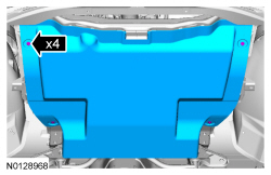
- Start the engine and move the selector lever slowly through each gear, stopping in each position and allowing the transmission to engage.
- With the engine running in PARK on a level hoist make sure the transmission is at normal operating temperature 85-93Âş C (185-200Âş F). Check the transmission fluid is even with the oil leveling plug hole.
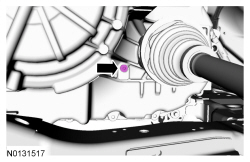
- NOTICE: Use only transmission fluid specific for this
transmission. Do not use any supplemental transmission fluid additives or
cleaning agents. The use of these products can cause internal transmission
components to fail, which will affect the operation of the transmission.
If the transmission fluid is not even with the oil leveling plug hole, add clean transmission fluid in increments of 0.25L (0.5 pt) until the transmission fluid is even with the oil leveling plug hole.
Materials: Motorcraft MERCON LV Automatic Transmission Fluid XT-10-QLVC.
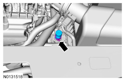
-
- Tighten to 8 Nm (71 lb-in).
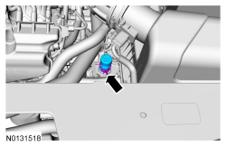
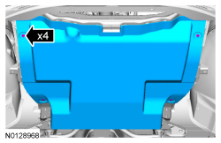
Transmission Fluid Drain and Refill
Material

- With the vehicle in NEUTRAL, position it on a hoist. For additional information, refer to Section 100-02.
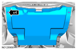
- NOTE: If an internal problem is suspected, drain the transmission
fluid through a paper filter. A small amount of metal or friction particles
may be found from normal wear. If an excessive amount of metal or friction
material is present, the transmission will need to be overhauled.
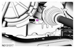
Remove the drain plug and drain the transmission fluid. Install the drain plug.
- Tighten to 12 Nm (106 lb-in).
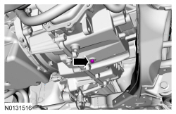
- Compress the constant tension clamp and remove the transmission vent from the fill tube.
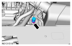
- NOTICE: Use only transmission fluid specific for this
transmission. Do not use any supplemental transmission fluid additives or
cleaning agents. The use of these products can cause internal transmission
components to fail, which will affect the operation of the transmission.
NOTICE: The following fluid amounts listed below are for initial fill only. The transmission fluid must be even with the oil leveling plug hole and the transmission must be at normal operating temperature 85-93Âş C (185-200Âş F) or transmission damage can occur.
Refer to the chart below and fill the transmission to the initial fill amount with clean transmission fluid.

- Start the engine and move the selector lever slowly through each gear, stopping in each position and allowing the transmission to engage.
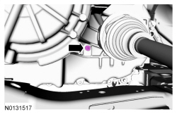
- With the engine running in PARK on a level hoist, remove the oil
leveling plug and allow the transmission fluid to drain until its even with
the oil leveling plug hole. If the transmission fluid does not drain from
the oil leveling plug hole add transmission fluid in increments of.25 L
(0.264 qt) until the transmission fluid is even with the oil leveling plug
hole. Install the oil leveling plug.
Materials: Motorcraft MERCON LV Automatic Transmission Fluid XT-10-QLVC.- Tighten to 8 Nm (71 lb-in).
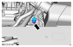
- With the clamp facing the front of the vehicle, compress the constant tension clamp and install the transmission vent on the fill tube.
- Drive the vehicle until the transmission is at normal operating temperature 85-93Âş C (185-200Âş F).
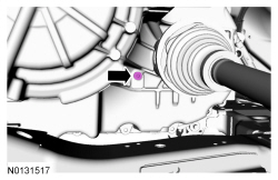
- With the engine running in PARK on a level hoist at normal operating
temperature 85-93Âş C (185-200Âş F), remove the oil leveling plug and allow
the transmission fluid to drain until it is even with the oil leveling plug
hole. Install the oil leveling plug.
- Tighten to 8 Nm (71 lb-in).
Transmission Fluid Exchange
Special Tool(s)

Material

NOTICE: Use transmission fluid specific for this transmission. Do not use any supplemental transmission fluid additives or cleaning agents. The use of these products can cause internal transmission components to fail, which will affect the operation of the transmission.
- With the vehicle in NEUTRAL, position it on a hoist. For additional information, refer to Section 100-02.
- Use the ATF Fluid Exchanger W/Power Steering Fluid Exchanger to change the fluid.
- Connect the ATF Fluid Exchanger W/Power Steering Fluid Exchanger to the transmission fluid cooler tube after the transmission fluid cooler on the return tube. This will help remove any foreign material trapped in the transmission fluid coolers.
- Perform the transmission fluid exchange using the ATF Fluid Exchanger W/Power Steering Fluid Exchanger. Follow the manufacturer's instructions included with the machine.
- Once the transmission fluid exchange is completed, disconnect the ATF Fluid Exchanger W/Power Steering Fluid Exchanger. Reconnect any disconnected transmission fluid cooler tubes.
- With the engine running, check and make sure the transmission is at normal operating temperature 85-93Âş C (185-200Âş F). Check and adjust the transmission fluid level, refer to Transmission Fluid Level Check in this section. Check for leaks.
 Diagnosis and Testing
Automatic Transmission
Special Tool(s)
Material
DTC Chart
Diagnostics in this manual assume a certain skill level and knowledge of
Ford-specific diagnostic practices. Refer to Diagnostic Method ...
 Removal and Installation
Main Control Cover
Material
Removal
With the vehicle in NEUTRAL, position it on a hoist. Refer to Section
100-02.
Remove the ACL assembly. Refer to Section 303-12.
...
Other materials:
Exhaust System
SPECIFICATIONS
Torque Specifications
a Refer to the procedure in this section.
DESCRIPTION AND OPERATION
Exhaust System
Component Location
The 2.0L Gasoline Turbocharged Direct Injection (GTDI) exhaust system
consists of:
a one-piece catalytic converter manifold that is mounted to the
tur ...
Collision Avoidance
DESCRIPTION AND OPERATION
Forward Collision Warning
Overview
The forward collision warning system alerts the driver of a collision risk
with a red warning LED indicator bar located above the instrument panel (part of
the HUD module) and an audible warning chime from the IPC. The
AB ...
Capacities and Specifications
Engine Drivebelt Routing
3.5L V6 engine
3.5L V6 SHO engine
2.0L EcoBoost engine
...
