SPECIFICATIONS
Material
Torque Specifications
DESCRIPTION AND OPERATION
Intake Air Distribution and Filtering
2.0L GTDI
The air intake system consists of the:
- ACL assembly.
- ACL element.
- ACL outlet pipe.
- CAC.
- CAC tubes.
The air intake system:
- cleans intake air with a replaceable, dry-type ACL element.
The engine ACL contains an ACL element made of treated, pleated paper. A new ACL element must be installed periodically as scheduled. Engine performance and fuel economy are adversely affected when maximum restriction of the ACL element is reached.
The CAC subsystem cools and increases the density of the compressed turbocharged air.
3.5L Ti-VCT, 3.7L Ti-VCT
The air intake system consists of the:
- ACL assembly.
- ACL outlet pipe.
- ACL element.
The air intake system:
- cleans intake air with a replaceable, dry-type ACL element.
The engine ACL contains an ACL element made of treated, pleated paper. A new ACL element must be installed periodically as scheduled. Engine performance and fuel economy are adversely affected when maximum restriction of the ACL element is reached.
3.5L GTDI
The air intake system consists of the:
- ACL assembly.
- ACL element.
- ACL outlet pipe.
- CAC.
- CAC pipes and tubes.
- turbocharger intake pipe.
- turbocharger intake tubes.
The air intake system:
- cleans intake air with a replaceable, dry-type ACL element.
The engine ACL contains an ACL element made of treated, pleated paper. A new ACL element must be installed periodically as scheduled. Engine performance and fuel economy are adversely affected when maximum restriction of the ACL element is reached.
The CAC subsystem cools and increases the density of the compressed turbocharged air.
DIAGNOSIS AND TESTING
Intake Air Distribution and Filtering
Refer to the Powertrain Control/Emissions Diagnosis (PC/ED) manual.
GENERAL PROCEDURES
Charge Air Cooler (CAC) Cleaning
Material
Charge Air Cooler (CAC) Cleaning
- NOTICE: Do not use a high-pressure power washer to clean the
Charge Air Cooler (CAC) or damage to the CAC may
occur.
NOTE: Drain all contaminates such as coolant, fuel and oil prior to cleaning the Charge Air Cooler (CAC).
NOTE: Thoroughly clean the joint clamp areas as well as the turbocharger connection, engine connection and the CAC connections, using metal brake parts cleaner.
Lay the CAC flat with the inlet and outlet ports pointing up.
- NOTE: Plug or cap the CAC openings
prior to agitating.
Add an appropriate amount of commercially available detergent cleaner such as Simple Green Pro HD, or equivalent to the CAC. Follow the manufacturer's directions for cleaning. Fill the CAC to 40% of its volume with water.
- Raise one end of the CAC and agitate it by hand for at least 5 minutes.
- Raise the opposite end of the CAC and agitate it by hand for at least 5 minutes.
- Drain the CAC.
- Flush the CAC thoroughly with clean water.
- Repeat Steps 1 through 6 until no contaminates are found in the flush water.
- Allow the CAC to air dry.
- NOTE: The following leak test steps must by performed prior
to installing the CAC.
Install the CAC Y-pipe, gasket and bolts.
- To install, tighten to 8 Nm (71 lb-in).
- NOTE: Use a commercially available kit, such as the Johnson
Manufacturing Company Charge Air Cooler Test Set Part No. 351-CAS, or
equivalent.
Install the commercially available CAC cooler tester on the CAC following the manufacturer's installation instructions.
- Tighten the clamps to 5 Nm (44 lb-in).
- WARNING: Never exceed the specified pressure. Excessive pressure may
cause the test adapter to blow off or may damage the charge air cooler
(CAC). Failure to follow this instruction may result in serious personal
injury.
Slowly apply air pressure to 150 kPa (22 psi).
- Let the CAC stand
for a few minutes and note any loss in pressure.
- Release the air pressure.
- Repeat Steps 11 and 12 as many times as necessary to verify the
readings. The reading is considered verified when 3 consecutive tests show
approximately the same pressure drop.
- If the pressure loss exceeds 10 kPa (1.5 psi) per minute, install a new CAC. For additional information, refer to Charge Air Cooler in this section.
REMOVAL AND INSTALLATION
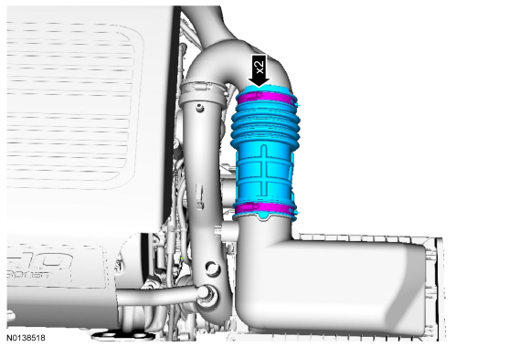
Air Cleaner
Removal and Installation
NOTICE: Whenever turbocharger air intake system components are removed, always cover open ports to protect from debris. It is important that no foreign material enter the system. The turbocharger compressor vanes are susceptible to damage from even small particles. All components should be inspected and cleaned, if necessary, prior to installation or reassembly.
NOTICE: 3.5L Ti-VCT shown, others similar.
-
- Refer to Section 310-00.
- To install, reverse the removal procedure.
Air Cleaner Outlet Pipe - 2.0L GTDI
Removal and Installation
NOTICE: Whenever turbocharger air intake system components are removed, always cover open ports to protect from debris. It is important that no foreign material enter the system. The turbocharger compressor vanes are susceptible to damage from even small particles. All components should be inspected and cleaned, if necessary, prior to installation or reassembly.
-
- Refer to Section 310-00.
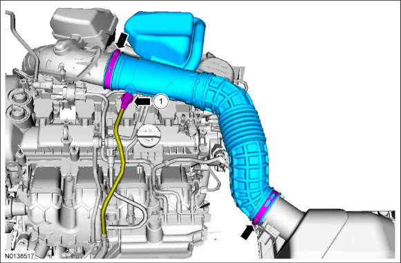
- To install, reverse the removal procedure.
Air Cleaner Outlet Pipe - 3.5L Ti-VCT
Removal and Installation
-
- Refer to Section 310-00.
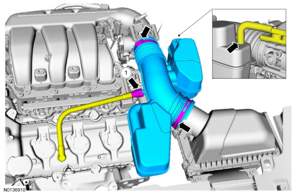
- To install, reverse the removal procedure.
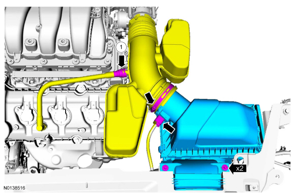
Air Cleaner Outlet Pipe - 3.5L GTDI
Removal and Installation
NOTICE: Whenever turbocharger air intake system components are removed, always cover open ports to protect from debris. It is important that no foreign material enter the system. The turbocharger compressor vanes are susceptible to damage from even small particles. All components should be inspected and cleaned, if necessary, prior to installation or reassembly.
- To install, reverse the removal procedure.
Charge Air Cooler
Removal and Installation
NOTICE: Whenever turbocharger air intake system components are removed, always cover open ports to protect from debris. It is important that no foreign material enter the system. The turbocharger compressor vanes are susceptible to damage from even small particles. All components should be inspected and cleaned, if necessary, prior to installation or reassembly.
- Remove the radiator. For additional information, refer to Section 303-03.
- Remove the CAC.
- Inspect and install a new CAC adapter gasket, if necessary.
- To install, reverse the removal procedure.
 Engine Emission Control
SPECIFICATIONS
Material
Torque Specifications
DESCRIPTION AND OPERATION
Engine Emission Control
Component Locations
2.0L GTDI
3.5L Ti-VCT and
3.7L Ti-VCT
3.5L GTDI
S ...
 Evaporative Emissions
SPECIFICATIONS
Torque Specifications
DESCRIPTION AND OPERATION
Evaporative Emissions
The EVAP system
consists of the:
EVAP canister purge valve.
EVAP canister.
dust ...
Other materials:
Disassembly and Assembly of Subassemblies
Cylinder Head
Special Tool(s)
Material
Cylinder Head
NOTE: RH shown, LH similar.
Disassembly
NOTE: If the components are to be reinstalled, they must be installed
in the same positions. Mark the components for installation into their original
locations.
Using the Valve Spring Comp ...
Diagnosis and Testing
Engine Cooling
Special Tool(s)
Material
Principles of Operation
Engine coolant flows primarily from the engine to the radiator circuit and
back to the coolant pump. Coolant is sent from the coolant pump through the
engine block and cylinder heads. Separate circuits from the engine also feed the ...
Removal and Installation
Main Control Cover
Material
Removal
With the vehicle in NEUTRAL, position it on a hoist. Refer to Section
100-02.
Remove the ACL assembly. Refer to Section 303-12.
Drain the fluid.
Tighten to 12 Nm (106 lb-in).
NOTE: Note ...
