SPECIFICATIONS
Material
Torque Specifications
DESCRIPTION AND OPERATION
Engine Emission Control
Component Locations
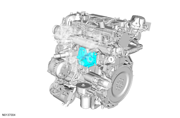
2.0L GTDI
3.5L Ti-VCT and 3.7L Ti-VCT
3.5L GTDI
System Operation
Refer to the PC/ED manual section 1 Description and Operation.
Component Description
Refer to the PC/ED manual section 1 Description and Operation.
DIAGNOSIS AND TESTING
Engine Emission Control
For PCM DTCs, refer to Section 303-14 DTC Chart: PCM. For driveability symptoms without DTCs, refer to the PC/ED manual, section 3 Symptom Charts.
REMOVAL AND INSTALLATION
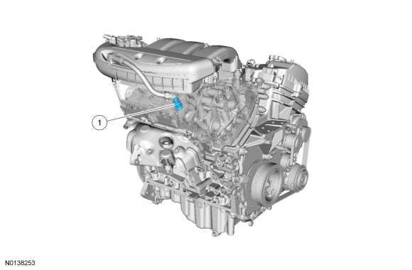
Crankcase Vent Oil Separator - 2.0L GTDI
Removal and Installation
NOTE: Removal steps in this procedure may contain installation details.
- Remove the intake manifold. For additional information, refer to Section 303-01C.
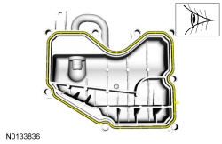
- NOTE: Clean and inspect the gasket mating surfaces.
- Tighten to 10 Nm (89 lb-in).
- Inspect and replace the crankcase vent oil separator gasket as necessary. Visual check.
- To install, reverse the removal procedure.
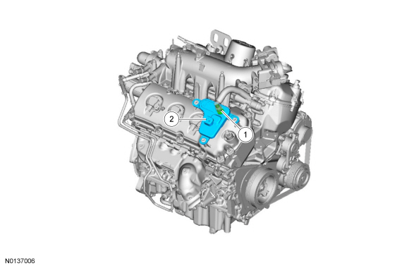
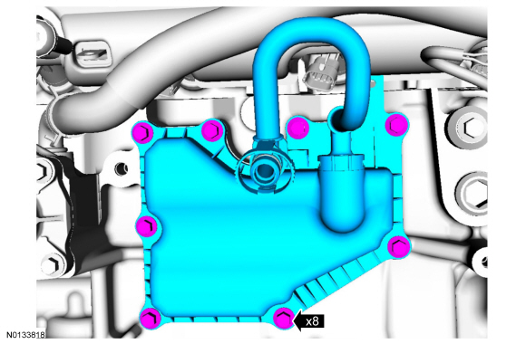
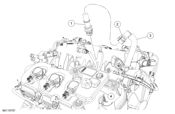
Crankcase Vent Oil Separator - 3.5L GTDI
Removal and Installation
- Release the wire harness pin-type retainer from the crankcase vent oil separator.
- Disconnect the crankcase ventilation tube-to-PCV valve quick connect coupling. For additional information, refer to Section 310-00.
- Remove the 3 crankcase vent oil separator bolts.
- To install, tighten to 8 Nm (71 lb-in).
- Remove the crankcase vent oil separator from the RH valve cover.
- To install, reverse the removal procedure.
Positive Crankcase Ventilation (PCV) Valve - 3.5L Ti-VCT
Material
Removal and Installation
NOTE: Removal steps in this procedure may contain installation details.
- NOTICE: A new PCV valve
must be installed if removed from the valve cover. Damage will occur to the
locking mechanism on the PCV valve.
Minor component movement CCW. Discard the specified component. Follow local disposal regulations.
- To install, reverse the removal procedure. Apply the specified lubricant to the specified component.
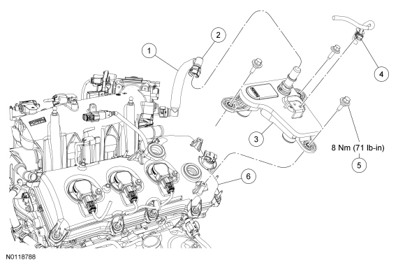
Positive Crankcase Ventilation (PCV) Valve - 3.5L GTDI
Material
Removal and Installation
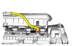
- Disconnect the crankcase ventilation tube-to-PCV valve quick connect coupling. For additional information, refer to Section 310-00.
- NOTICE: A new PCV valve must be installed if removed from the
valve cover. Damage will occur to the locking mechanism on the PCV valve.
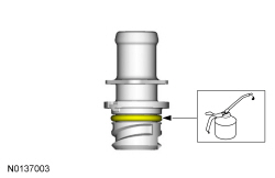
NOTE: To install, apply clean engine oil to the O-ring seal.
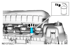
Rotate the PCV valve counterclockwise and remove from the crankcase vent oil separator.- Discard the PCV valve.
- To install, reverse the removal procedure.
- Install a new PCV valve.
Positive Crankcase Ventilation (PCV) Valve - 3.7L Ti-VCT
Material
Removal and Installation
NOTE: Removal steps in this procedure may contain installation details.

- NOTICE: A new PCV valve
must be installed if removed from the valve cover. Damage will occur to the
locking mechanism on the PCV valve.
Minor component movement CCW. Discard the specified component. Follow local disposal regulations.

- To install, reverse the removal procedure. Apply the specified lubricant to the specified component.

 Engine Ignition - 3.7L Ti-VCT
SPECIFICATIONS
Material
General Specifications
Torque Specifications
DESCRIPTION AND OPERATION
Engine Ignition
Component Location
3.7L Ti-VCT
System Operation
REFER to the PC/ED m ...
 Intake Air Distribution and Filtering
SPECIFICATIONS
Material
Torque Specifications
DESCRIPTION AND OPERATION
Intake Air Distribution and Filtering
2.0L GTDI
The air intake system consists of the:
ACL assembly.
ACL&nbs ...
Other materials:
Active park assist
WARNING: This system is designed to be a supplementary park
aid. It may not work in all conditions and is not intended to
replace the driver’s attention and judgment. The driver is responsible
for avoiding hazards and maintaining a safe distance and speed, even
when the system is in use.
Note ...
Audio System
GENERAL INFORMATION
Radio Frequencies and Reception Factors
AM and FM frequencies are established by the Federal Communications
Commission (FCC) and the Canadian Radio and Telecommunications
Commission (CRTC). Those frequencies are:
AM: 530, 540–1700, 1710 kHz
FM: 87.9–107.7, 107.9 MHz
...
Personal Safety System
The Personal Safety System provides an improved overall level of frontal
crash protection to front seat occupants and is designed to help further
reduce the risk of airbag-related injuries. The system is able to analyze
different occupant conditions and crash severity before activating the
appro ...
