SPECIFICATIONS
Material
Torque Specifications
a Refer to the procedure in this section.
DESCRIPTION AND OPERATION
Electronic Engine Controls
Component Location
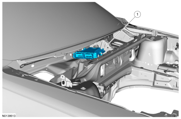
PCM Location - 3.5L Ti-VCT, 3.7L Ti-VCT
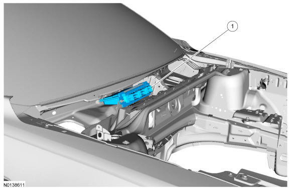
PCM Location - 2.0L GTDI, 3.5L GTDI
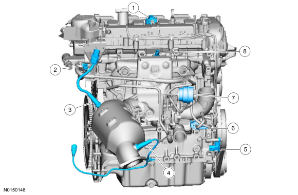
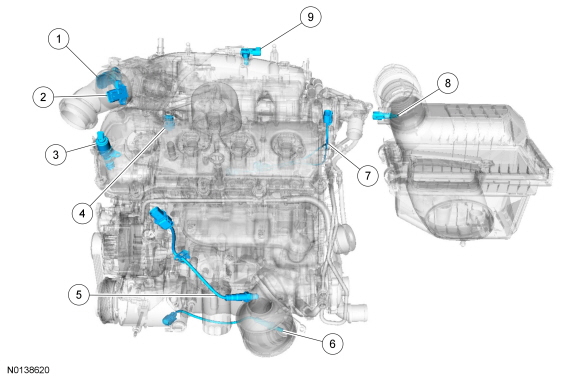
Front Engine Sensor Locations - 2.0L GTDI
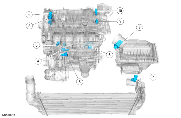
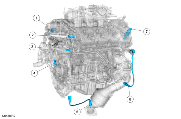
Rear Engine Sensor Locations - 2.0L GTDI
Front Engine Sensor Locations - 3.5L Ti-VCT, 3.7L Ti-VCT
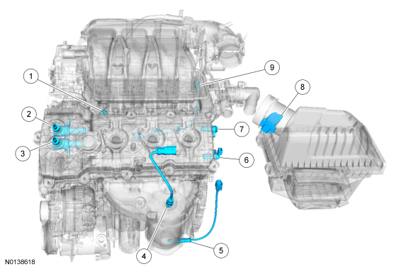
Rear Engine Sensor Locations - 3.5L Ti-VCT, 3.7L Ti-VCT

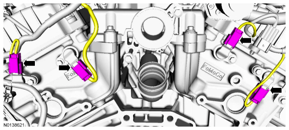
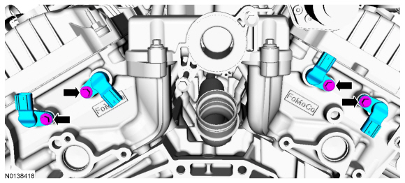
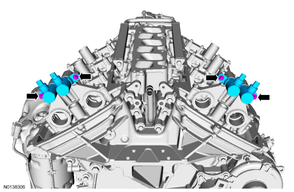
Front Engine Sensor Locations - 3.5L GTDI
Rear Engine Sensor Locations - 3.5L GTDI
Overview
REFER to the Powertrain Control/Emissions Diagnosis (PC/ED) manual Section 1 Description and Operation.
DIAGNOSIS AND TESTING
Electronic Engine Controls
DTC Charts
PCM DTC Chart
REMOVAL AND INSTALLATION
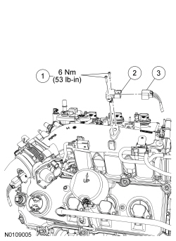
Camshaft Position (CMP) Sensor - 2.0L GTDI
Material
Removal
NOTE: Removal steps in this procedure may contain installation details.
- Remove the ACL outlet pipe. Refer to Section 303-12.
- NOTE: Lubricate the O-ring seal with clean engine oil prior to
installing the CMP sensor.
- To install, tighten to 6 Nm (53 lb-in).
Installation
- To install, reverse the removal procedure.
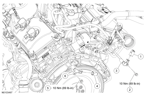
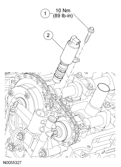
Camshaft Position (CMP) Sensor - 3.5L Ti-VCT, 3.7L Ti-VCT
Material
Removal
NOTE: Removal steps in this procedure may contain installation details.
- Remove the Air Cleaner (ACL) outlet pipe and the ACL. For additional information, refer to Section 303-12.
-
- To install, tighten to 10 Nm (89 lb-in).
Installation
- To install, reverse the removal procedure.
- Apply the specified lubricant to the specified component.
Motorcraft SAE 5W-20 Premium Synthetic Blend Motor Oil (US); Motorcraft SAE 5W-20 Super Premium Motor Oil (Canada) XO-5W20-QSP (US); CXO-5W20-LSP12 (Canada).
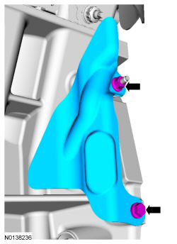
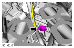
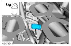
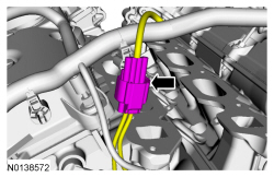
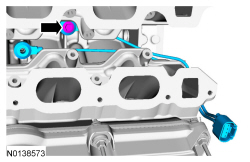
Camshaft Position (CMP) Sensor - 3.5L GTDI
Material
NOTE: Lower radiator hose removed for clarity.
Removal and Installation
Both sensors
- Remove the ACL outlet pipe and the ACL. Refer to Section 303-12.
RH sensor
- Position the RH turbocharger intake tube aside. Refer to Section 303-12.
LH sensor
- Position the LH turbocharger intake tube aside. Refer to Section 303-12.
Both sensors
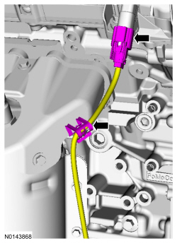
- Disconnect the CMP sensor electrical connector.
- Remove the bolt and the CMP sensor.
- To install, tighten to 10 Nm (89 lb-in).
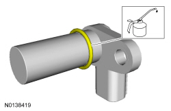
- NOTE: Lubricate the CMP sensor
O-ring seal with clean engine oil.
To install, reverse the removal procedure.
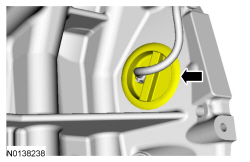
Crankshaft Position (CKP) Sensor - 2.0L GTDI
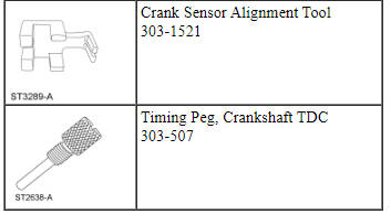
Special Tool(s)
Removal
NOTICE: Do not loosen or remove the crankshaft pulley bolt without first installing the special tools as instructed in this procedure. The crankshaft pulley and the crankshaft timing sprocket are not keyed to the crankshaft. The crankshaft, the crankshaft sprocket and the pulley are fitted together by friction, using diamond washers between the flange faces on each part. For that reason, the crankshaft sprocket is also unfastened if the pulley bolt is loosened. Before any repair requiring loosening or removal of the crankshaft pulley bolt, the crankshaft and camshafts must be locked in place by the special service tools, otherwise severe engine damage can occur.
NOTICE: During engine repair procedures, cleanliness is extremely important. Any foreign material, including any material created while cleaning gasket surfaces, that enters the oil passages, coolant passages or the oil pan can cause engine failure.
- With the vehicle in NEUTRAL, position it on a hoist. For additional information, refer to Section 100-02.
- Remove the RH fender splash shield. For additional information, refer to Section 501-02.

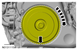
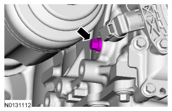
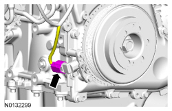
- NOTE: Turn the engine in the normal direction of rotation only.
Using the crankshaft pulley bolt, turn the crankshaft clockwise to position the TDC marked tooth on the crankshaft pulley (located on the 20th tooth counterclockwise from the missing tooth) at the 6 o'clock position.
- Special Tool(s): Timing Peg, Crankshaft TDC 303-507.
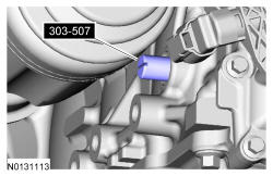
- NOTE: The Crankshaft TDC Timing
Peg will contact the crankshaft and prevent it from turning past TDC.
However, the crankshaft can still be rotated in the counterclockwise
direction. The crankshaft must remain at the TDC position
during the CKP sensor
removal and installation.
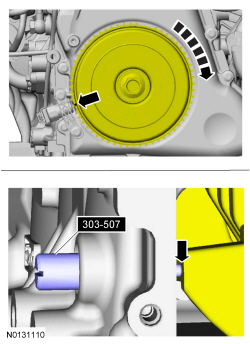
NOTE: The engine front cover is shown removed in graphic for clarity.
Slowly rotate the crankshaft clockwise until the crankshaft contacts the Crankshaft TDC Timing Peg.
Special Tool(s): Timing Peg, Crankshaft TDC 303-507.- The TDC marked tooth on the crankshaft pulley will align with the center line of the CKP sensor.

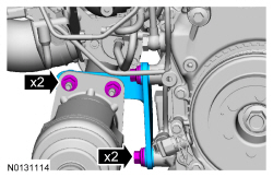
Installation
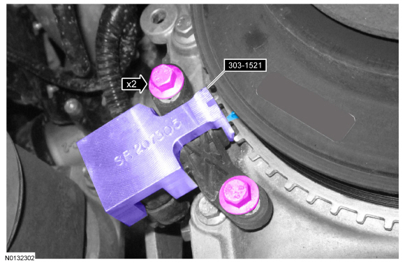
- Do not tighten bolts at this time.
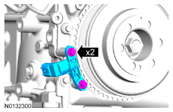

- Special Tool(s): Crankshaft Sensor Alignment Tool 303-1521.
- If the Crankshaft Sensor Alignment Tool does not align with the TDC marked
tooth on the crankshaft pulley, loosen the 2 CKP sensor
bolts and adjust the sensor until the tool is installed.
- Tighten to 7 Nm (62 lb-in).
- Remove the Crankshaft Sensor Alignment Tool.
- If the Crankshaft Sensor Alignment Tool does not align with the TDC marked
tooth on the crankshaft pulley, loosen the 2 CKP sensor
bolts and adjust the sensor until the tool is installed.
- Remove the Special Tool(s): Crankshaft TDC Timing Peg 303-507.

-
- Tighten to 20 Nm (177 lb-in).

-
- Tighten to 25 Nm (18 lb-ft).

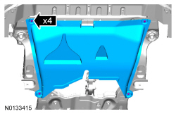
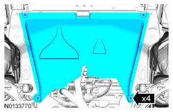
- Install the underbody shield and tighten the 4 retainers.

- Install the RH fender splash shield. For additional information, refer to Section 501-02.
- After completing the repairs, use the scan tool to perform the Misfire Monitor Neutral Profile Correction procedure, following the on-screen instructions.
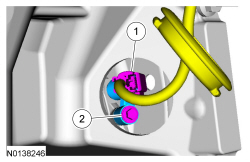
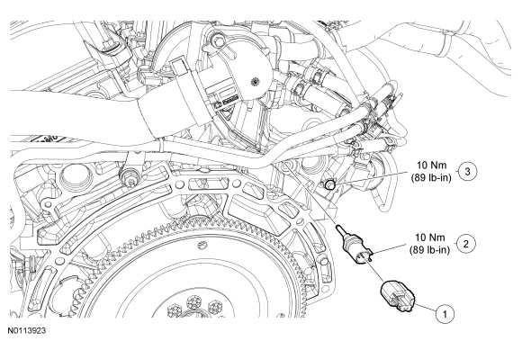
Crankshaft Position (CKP) Sensor - 3.5L GTDI, 3.5L Ti-VCT, 3.7L Ti-VCT
Special Tool(s)
Removal and Installation
All vehicles
- With the vehicle in NEUTRAL, position it on a hoist. For additional information, refer to Section 100-02.
3.5L GTDI vehicles
- Remove the LH turbocharger. For additional information, refer to Section 303-04D.
All vehicles
-
- To install, tighten to 10 Nm (89 lb-in).
- NOTICE: Remove the bolt and the CKP sensor
from the bell housing before disconnecting the electrical connector to
prevent the CKP sensor
from falling in the bell housing.
NOTE: Follow the unique instructions or graphic for this step in installation.

Installation
All vehicles
- To install, reverse the removal procedure.
-
- 2. Tighten to 10 Nm (89 lb-in).
3.5L GTDI
- Using the scan tool, perform the Misfire Monitor Neutral Profile Correction procedure, following the on-screen instructions.
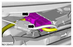
Powertrain Control Module (PCM) - 2.0L GTDI, 3.5L GTDI
Removal
- NOTE: PCM installation DOES NOT require new keys or programming
of keys.
Retrieve the module configuration. Carry out the module configuration retrieval steps of the PMI procedure. For additional information, refer to Section 418-01.
- Remove the cowl panel grille. For additional information, refer to Section 501-02.
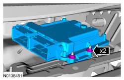
Installation
-
- Tighten to 8 Nm (71 lb-in).


- Install the cowl panel grille. For additional information, refer to Section 501-02.
- NOTE: If the Programmable Module Installation (PMI) procedure was
not successful in downloading the data from the vehicles original PCM, then
the oil life data of the vehicle is lost. If this occurs, and the oil life
cannot be determined through service history or customer interview, it is
recommended the vehicle engine oil and filter be changed and the oil change
minder reset.
Restore the module configuration. Carry out the module configuration restore steps of the Programmable Module Installation (PMI) procedure. For additional information, refer to Section 418-01.
- Reprogram the Passive Anti-Theft System (PATS). Carry out the Parameter Reset procedure. For additional information, refer to Section 419-01B.
- After completing the repairs, use the scan tool to perform the Misfire Monitor Neutral Profile Correction procedure, following the on-screen instructions.
Powertrain Control Module (PCM) - 3.5L Ti-VCT, 3.7L Ti-VCT
Removal
- NOTE: PCM installation DOES NOT require new keys or programming
of keys.
Retrieve the module configuration. Carry out the module configuration retrieval steps of the PMI procedure. For additional information, refer to Section 418-01.
- Remove the cowl panel grille. For additional information, refer to Section 501-02.
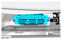
Installation
-
- Tighten to 8 Nm (71 lb-in).


- Install the cowl panel grille. For additional information, refer to Section 501-02.
- NOTE: If the Programmable Module Installation (PMI) procedure was
not successful in downloading the data from the vehicles original PCM, then
the oil life data of the vehicle is lost. If this occurs, and the oil life
cannot be determined through service history or customer interview, it is
recommended the vehicle engine oil and filter be changed and the oil change
minder reset.
Restore the module configuration. Carry out the module configuration restore steps of the Programmable Module Installation (PMI) procedure. For additional information, refer to Section 418-01.
- Reprogram the Passive Anti-Theft System (PATS). Carry out the Parameter Reset procedure. For additional information, refer to Section 419-01B.
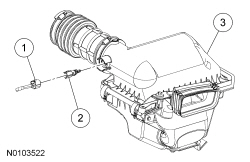
Mass Air Flow (MAF) Sensor
Removal and Installation
NOTE: Removal steps in this procedure may contain installation details.
-
- To install, tighten to 2 Nm (18 lb-in).
- To install, reverse the removal procedure.
Cylinder Head Temperature (CHT) Sensor - 2.0L GTDI
Removal
NOTE: Removal steps in this procedure may contain illustration details.
- Remove the ACL outlet pipe and the turbocharger inlet pipe. For additional information, refer to Section 303-12.
-
- To install, tighten to 10 Nm (89 lb-in).
Installation
- To install, reverse the removal procedure.
- Install a new CHT sensor.
Cylinder Head Temperature (CHT) Sensor - 3.5L Ti-VCT, 3.7L Ti-VCT
Removal
NOTE: Removal steps in this procedure may contain installation details.
- Remove the lower intake manifold. For 3.5L Ti-VCT, refer to Section 303-01A. For 3.7L Ti-VCT, refer to Section 303-01D.
- Discard the specified component. Follow local disposal regulations.
- To install, tighten to 10 Nm (89 lb-in).
Installation
- To install, reverse the removal procedure.
- Install a new CHT sensor.
Cylinder Head Temperature (CHT) Sensor - 3.5L GTDI
- Remove the Air Cleaner (ACL) outlet pipe and the ACL. For additional information, refer to Section 303-12.
- Position the ACL -to-RH turbocharger intake tube aside. For additional information, refer to Section 303-12.
- Remove the ground wire-to-engine front cover bolt.
- Disconnect the Cylinder Head Temperature (CHT) sensor electrical connector.
- Remove and discard the CHT sensor.
- To install, tighten to 10 Nm (89 lb-in).
- To install, reverse the removal procedure.
- Do not reuse the CHT sensor. Install a new sensor.
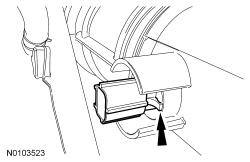
Throttle Position (TP) Sensor
Removal
- Remove the Charge Air Cooler (CAC) outlet pipe. For additional information, refer to Section 303-12.
- Disconnect the Throttle Position (TP) sensor electrical connector.

- NOTICE: Do not put direct heat on the Throttle Position (TP)
sensor or any other plastic parts because heat damage may occur. Damage may
also occur if Electronic Throttle Body (ETB) temperature exceeds 120ÂşC
(248ÂşF).
NOTE: Do not use power tools.
Remove the TP sensor.- Using a suitable heat gun, apply heat to the top of the Electronic Throttle Body (ETB) until the top TP sensor bolt ear reaches approximately 55ÂşC (130ÂşF), this should take no more than 3 minutes using an 1,100-watt heat gun. The heat gun should be about 25.4 mm (1 in) away from the ETB.
- Monitor the temperature of the top TP sensor bolt ear on the ETB with a suitable temperature measuring device, such as a digital temperature laser or infrared thermometer, while heating the ETB.
- Using hand tools, quickly remove the bolt farthest from the heat source first and discard.
- Using hand tools, remove the remaining bolt and discard.
- Remove and discard the TP sensor.
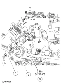
Installation
- NOTE: When installing the new TP sensor, make sure that the
radial locator tab on the TP sensor is aligned with the radial locator hole
on the ETB.
NOTE: Do not use power tools.
Install the new TP sensor.- Using hand tools, install the 2 new bolts.
- Tighten to 3 Nm (27 lb-in).
- Using hand tools, install the 2 new bolts.
- Connect the TP sensor electrical connector.
- Install the CAC outlet pipe. For additional information, refer to Section 303-12.
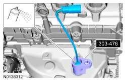
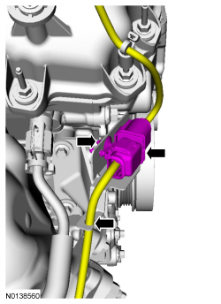
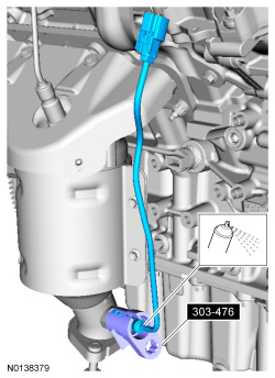
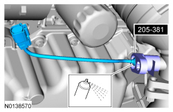
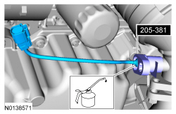
Heated Oxygen Sensor (HO2S) - 2.0L GTDI
Special Tool(s)
Material
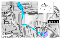
Removal
- With the vehicle in NEUTRAL, position it on a hoist. For additional information, refer to Section 100-02.

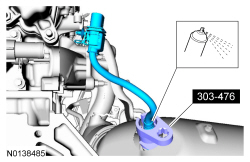
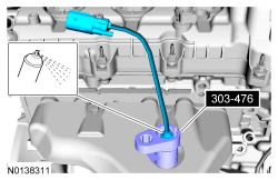
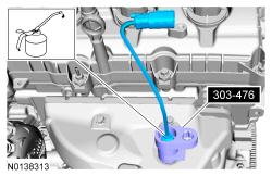
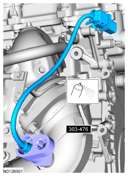
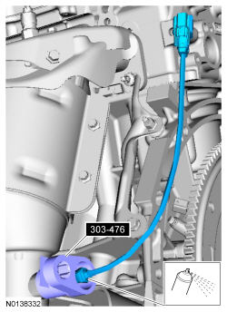
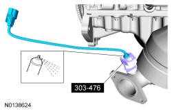
- Apply the specified chemical with a spray can.
Penetrating and Lock Lubricant (US); Penetrating Fluid (Canada) XL-1 (US); CXC-51-A (Canada).
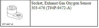
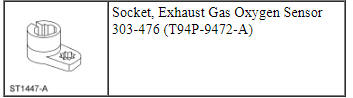
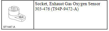
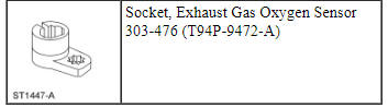
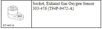
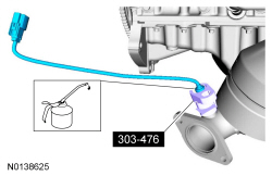
Special Tool(s): Socket, Exhaust Gas Oxygen Sensor 303-476 (T94P-9472-A).
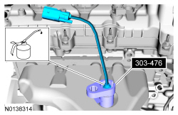
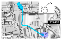
Installation
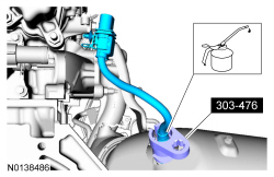
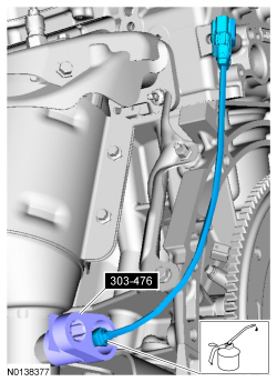
- Apply the specified lubricant to the specified component.
High Temperature Nickel Anti-Seize Lubricant XL-2.
Special Tool(s): Socket, Exhaust Gas Oxygen Sensor 303-476 (T94P-9472-A).- Calculate the correct torque wrench setting for the following torque. Refer to the Torque Wrench Adapter Formulas in the Appendix.
- Tighten to 48 Nm (35 lb-ft).

Heated Oxygen Sensor (HO2S) - 3.5L Ti-VCT, 3.7L Ti-VCT
Special Tool(s)
Material
Removal
RH sensor
- With the vehicle in NEUTRAL, position it on a hoist. Refer to Section 100-02.

- Apply the specified chemical with a spray can.
Penetrating and Lock Lubricant (US); Penetrating Fluid (Canada) XL-1 (US); CXC-51-A (Canada).
Special Tool(s): Socket, Exhaust Gas Oxygen Sensor 303-476 (T94P-9472-A).
LH sensor
- Apply the specified chemical with a spray can.
Penetrating and Lock Lubricant (US); Penetrating Fluid (Canada) XL-1 (US); CXC-51-A (Canada).
Special Tool(s): Socket, Exhaust Gas Oxygen Sensor 303-476 (T94P-9472-A).
Installation
RH sensor
- Apply the specified lubricant to the specified component.
High Temperature Nickel Anti-Seize Lubricant XL-2.
Special Tool(s): Socket, Exhaust Gas Oxygen Sensor 303-476 (T94P-9472-A).- Calculate the correct torque wrench setting for the following torque. Refer to the Torque Wrench Adapter Formulas in the Appendix.
- Tighten to 48 Nm (35 lb-ft).
LH sensor
- Apply the specified lubricant to the specified component.
High Temperature Nickel Anti-Seize Lubricant XL-2.
Special Tool(s): Socket, Exhaust Gas Oxygen Sensor 303-476 (T94P-9472-A).- Calculate the correct torque wrench setting for the following torque. Refer to the Torque Wrench Adapter Formulas in the Appendix.
- Tighten to 48 Nm (35 lb-ft).

Heated Oxygen Sensor (HO2S) - 3.5L GTDI
Special Tool(s)
Material
Removal
Both sensors
- With the vehicle in NEUTRAL, position it on a hoist. Refer to Section 100-02.
RH sensor

- Apply the specified chemical with a spray can.
Penetrating and Lock Lubricant (US); Penetrating Fluid (Canada) XL-1 (US); CXC-51-A (Canada).
Special Tool(s): Socket, Exhaust Gas Oxygen Sensor 303-476 (T94P-9472-A).
LH sensor
- Apply the specified chemical with a spray can.
Penetrating and Lock Lubricant (US); Penetrating Fluid (Canada) XL-1 (US); CXC-51-A (Canada).
Special Tool(s): Socket, Exhaust Gas Oxygen Sensor 303-476 (T94P-9472-A).
Installation
RH sensor
- Apply the specified lubricant to the specified component.
High Temperature Nickel Anti-Seize Lubricant XL-2.
Special Tool(s): Socket, Exhaust Gas Oxygen Sensor 303-476 (T94P-9472-A).- Calculate the correct torque wrench setting for the following torque. Refer to the Torque Wrench Adapter Formulas in the Appendix.
- Tighten to 48 Nm (35 lb-ft).
LH sensor
- Apply the specified lubricant to the specified component.
High Temperature Nickel Anti-Seize Lubricant XL-2.
Special Tool(s): Socket, Exhaust Gas Oxygen Sensor 303-476 (T94P-9472-A).- Calculate the correct torque wrench setting for the following torque. Refer to the Torque Wrench Adapter Formulas in the Appendix.
- Tighten to 48 Nm (35 lb-ft).


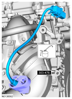
Catalyst Monitor Sensor - 2.0L GTDI
Special Tool(s)
Material
Removal
- With the vehicle in NEUTRAL, position it on a hoist. For additional information, refer to Section 100-02.


- Apply the specified chemical with a spray can.
Penetrating and Lock Lubricant (US); Penetrating Fluid (Canada) XL-1 (US); CXC-51-A (Canada).
Special Tool(s): Socket, Exhaust Gas Oxygen Sensor 303-476 (T94P-9472-A).
Installation
- Apply the specified lubricant to the specified component.
High Temperature Nickel Anti-Seize Lubricant XL-2.
Special Tool(s): Socket, Exhaust Gas Oxygen Sensor 303-476 (T94P-9472-A).- Calculate the correct torque wrench setting for the following torque. Refer to the Torque Wrench Adapter Formulas in the Appendix.
- Tighten to 48 Nm (35 lb-ft).


Catalyst Monitor Sensor - 3.5L Ti-VCT, 3.7L Ti-VCT
Special Tool(s)

Material
Removal
All sensors
- With the vehicle in NEUTRAL, position it on a hoist. Refer to Section 100-02.

RH sensor

- Apply the specified chemical with a spray can.
Penetrating and Lock Lubricant (US); Penetrating Fluid (Canada) XL-1 (US); CXC-51-A (Canada).
Special Tool(s): Socket, Exhaust Gas Oxygen Sensor 303-476 (T94P-9472-A).
LH sensor

- Apply the specified chemical with a spray can.
Penetrating and Lock Lubricant (US); Penetrating Fluid (Canada) XL-1 (US); CXC-51-A (Canada).
Special Tool(s): Socket, Exhaust Gas Oxygen Sensor 303-476 (T94P-9472-A).
Installation
RH sensor
- Apply the specified lubricant to the specified component.
High Temperature Nickel Anti-Seize Lubricant XL-2.
Special Tool(s): Socket, Exhaust Gas Oxygen Sensor 303-476 (T94P-9472-A).- Calculate the correct torque wrench setting for the following torque. Refer to the Torque Wrench Adapter Formulas in the Appendix.
- Tighten to 48 Nm (35 lb-ft).

LH sensor
- Apply the specified lubricant to the specified component.
High Temperature Nickel Anti-Seize Lubricant XL-2.
Special Tool(s): Socket, Exhaust Gas Oxygen Sensor 303-476 (T94P-9472-A).- Calculate the correct torque wrench setting for the following torque. Refer to the Torque Wrench Adapter Formulas in the Appendix.
- Tighten to 48 Nm (35 lb-ft).
Both sensors

Catalyst Monitor Sensor - 3.5L GTDI
Special Tool(s)
Material
Removal
Both sensors
- With the vehicle in NEUTRAL, position it on a hoist. Refer to Section 100-02.

RH sensor
- Apply the specified chemical with a spray can.
Penetrating and Lock Lubricant (US); Penetrating Fluid (Canada) XL-1 (US); CXC-51-A (Canada).
Special Tool(s): Socket, Exhaust Gas Oxygen Sensor 303-476 (T94P-9472-A).
LH sensor

- Apply the specified chemical with a spray can.
Penetrating and Lock Lubricant (US); Penetrating Fluid (Canada) XL-1 (US); CXC-51-A (Canada).
Special Tool(s): Socket, Exhaust Gas Oxygen Sensor 303-476 (T94P-9472-A).
Installation
RH sensor
- Apply the specified lubricant to the specified component.
High Temperature Nickel Anti-Seize Lubricant XL-2.
Special Tool(s): Socket, Exhaust Gas Oxygen Sensor 303-476 (T94P-9472-A).- Calculate the correct torque wrench setting for the following torque. Refer to the Torque Wrench Adapter Formulas in the Appendix.
- Tighten to 48 Nm (35 lb-ft).

LH sensor
- Apply the specified lubricant to the specified component.
High Temperature Nickel Anti-Seize Lubricant XL-2.
Special Tool(s): Socket, Exhaust Gas Oxygen Sensor 303-476 (T94P-9472-A).- Calculate the correct torque wrench setting for the following torque. Refer to the Torque Wrench Adapter Formulas in the Appendix.
- Tighten to 48 Nm (35 lb-ft).
Both sensors

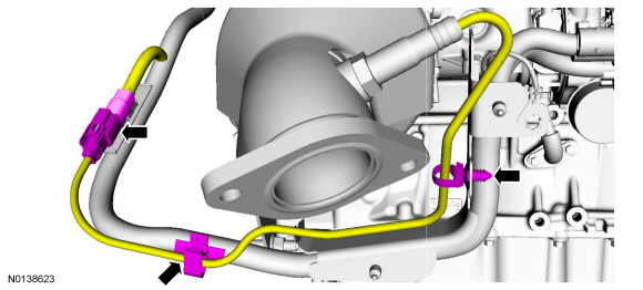
Fuel Rail Pressure (FRP) Sensor - 2.0L GTDI
Removal
- Release the fuel system pressure. For additional information, refer to Section 310-00.
- Disconnect the battery ground cable. For additional information, refer to Section 414-01.
- Remove the CAC inlet pipe. For additional information, refer to Section 303-12.

Installation
- Tighten in 5 stages.
- Stage 1: Tighten to 6 Nm (53 lb-in).
- Stage 2: Tighten an additional 5 degrees.
- Stage 3: Loosen 90 degrees.
- Stage 4: Tighten to 6 Nm (53 lb-in).
- Stage 5: Tighten an additional 21 degrees.

- Install the CAC inlet pipe. For additional information, refer to Section 303-12.
- Connect the battery ground cable. For additional information, refer to Section 414-01.
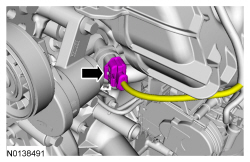
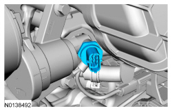
Fuel Rail Pressure (FRP) Sensor - 3.5L GTDI
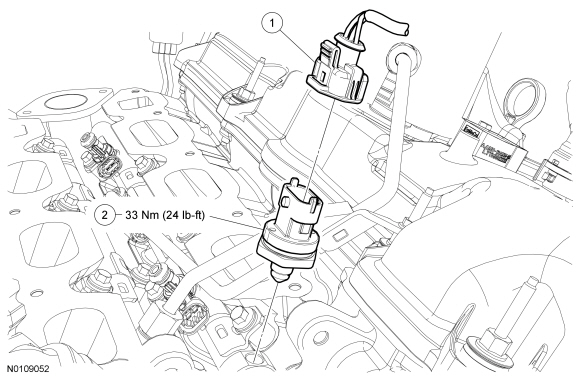
Removal and Installation
WARNING: Do not smoke, carry lighted tobacco or have an open flame of any type when working on or near any fuel-related component. Highly flammable mixtures are always present and may be ignited. Failure to follow these instructions may result in serious personal injury.
WARNING: Before working on or disconnecting any of the fuel tubes or fuel system components, relieve the fuel system pressure to prevent accidental spraying of fuel. Fuel in the fuel system remains under high pressure, even when the engine is not running. Failure to follow this instruction may result in serious personal injury.
- Release the fuel system pressure. For additional information, refer to Section 310-00.
- Disconnect the battery ground cable. For additional information, refer to Section 414-01.
- Remove the intake manifold. For additional information, refer to Section 303-01B.
- Disconnect the Fuel Rail Pressure (FRP) sensor electrical connector.
- Remove the FRP sensor.
- To install, tighten to 33 Nm (24 lb-ft).
- To install, reverse the removal procedure.
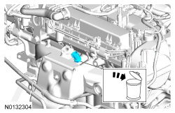
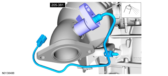
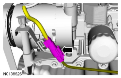
Knock Sensor (KS) - 2.0L GTDI
Removal
NOTE: Removal steps in this procedure may contain installation details.
- NOTICE: The RH KS must be installed in the 6 o'clock position
and the LH KS must be installed in the 3 o'clock position. Failure to follow
these instructions may result in damage to the engine.
- To install, tighten to 20 Nm (177 lb-in).
Installation
- To install, reverse the removal procedure.
Knock Sensor (KS) - 3.5L Ti-VCT, 3.7L Ti-VCT
Removal
NOTE: Removal steps in this procedure may contain installation details.
- Remove the coolant inlet pipe. For additional information, refer to Section 303-03.
-
- To install, tighten to 20 Nm (177 lb-in).
Installation
- To install, reverse the removal procedure.
Knock Sensor (KS) - 3.5L GTDI
Removal
NOTE: Removal steps in this procedure may contain installation details.
- Remove the coolant inlet pipe. For additional information, refer to Section 303-03.
-
- To install, tighten to 20 Nm (177 lb-in).
Installation
- To install, reverse the removal procedure.
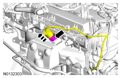
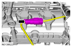
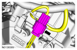
Variable Camshaft Timing (VCT) Oil Control Solenoid - 2.0L GTDI
Removal
NOTE: Removal steps in this procedure may contain installation details.
- Remove the valve cover. For additional information, refer to Section 303-01C.
-
- To install, tighten to 10 Nm (89 lb-in).
Installation
- To install, reverse the removal procedure.
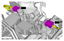
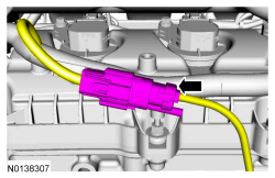
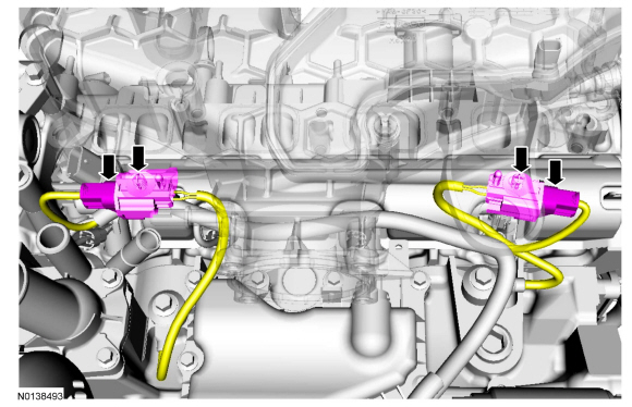
Variable Camshaft Timing (VCT) Oil Control Solenoid - 3.5L Ti-VCT, 3.7L Ti-VCT
Removal
NOTE: Removal steps in this procedure may contain installation details.
- Remove the LH or RH valve cover. For 3.5L Ti-VCT, refer to Section 303-01A. For 3.7L Ti-VCT, refer to Section 303-01D.
-
- To install, tighten in 2 stages.
- Stage 1: Tighten to 8 Nm (71 lb-in).
- Stage 2: Tighten an additional 20 degrees.
- To install, tighten in 2 stages.
Installation
- To install, reverse the removal procedure.
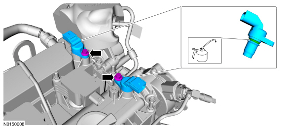
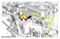
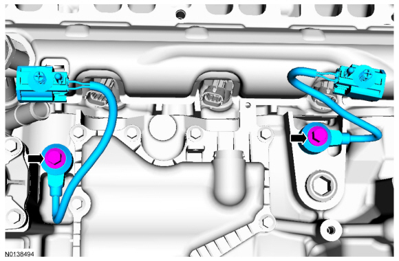
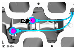
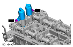
Variable Camshaft Timing (VCT) Oil Control Solenoid - 3.5L GTDI
Removal and Installation
- Remove the LH or RH valve cover. For additional information, refer to Section 303-01B.
- Remove the bolt and the Variable Camshaft Timing (VCT) oil control
solenoid.
- To install, tighten to 10 Nm (89 lb-in).
- To install, reverse the removal procedure.
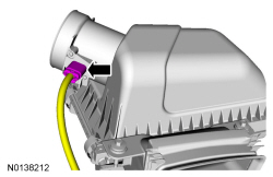
Intake Air Temperature (IAT) Sensor
Removal and Installation
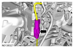
- Disconnect the Intake Air Temperature (IAT) sensor electrical connector.
- Remove the IAT sensor.
- Lift the tab and turn the IAT sensor counterclockwise to remove.
- To install, reverse the removal procedure.
- Make sure the IAT sensor tab is fully seated during installation.
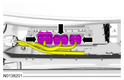
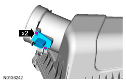
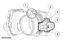
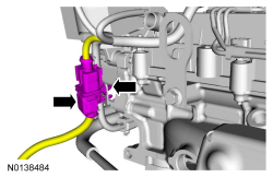
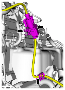
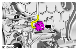
Turbocharger Boost Pressure (TCBP) / Charge Air Cooler Temperature (CACT) Sensor
Material
Removal
NOTE: Turbocharger Boost Pressure (TCBP)/ Charge Air Cooler Temperature (CACT)sensor and the Manifold Absolute Pressure (MAP)/Intake Air Temperature 2 (IAT2) sensor are not interchangeable.
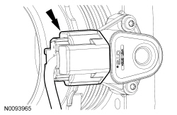
- Disconnect the TCBP / CACT sensor electrical connector.
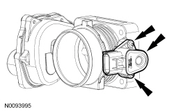
- Remove the 2 screws and the TCBP / CACT sensor.
Installation
- Lubricate the TCBP / CACT sensor O-ring seal with clean engine oil.
- Install the TCBP / CACT sensor and the 2 screws.
- Tighten to 3 Nm (27 lb-in).
- Connect the TCBP / CACT sensor electrical connector.
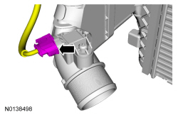
Manifold Absolute Pressure (MAP) Sensor
Removal
NOTE: Removal steps in this procedure may contain installation details.
-
- To install, tighten to 6 Nm (53 lb-in).
Installation
- To install, reverse the removal procedure.
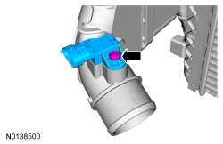
Manifold Absolute Pressure and Temperature (MAPT) Sensor
Removal
NOTE: Removal steps in this procedure may contain installation details.
-
- To install, tighten to 8 Nm (71 lb-in).
Installation
- To install, reverse the removal procedure.
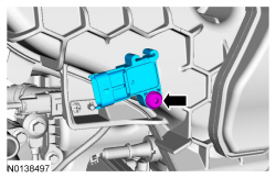
Manifold Absolute Pressure (MAP) / Intake Air Temperature 2 (IAT2) Sensor
Material
Removal
NOTE: The Turbocharger Boost Pressure (TCBP)/Charge Air Cooler Temperature (CACT) sensor and the Manifold Absolute Pressure (MAP)/ Intake Air Temperature 2 (IAT2) sensor are not interchangeable.
- Disconnect the MAP / IAT2 sensor electrical connector.
- Remove the 2 screws and the MAP / IAT2 sensor.
Installation
- Lubricate the MAP / IAT2 sensor O-ring seal with clean engine oil.
- Install the MAP / IAT2 sensor and the 2 screws.
- Tighten to 6 Nm (53 lb-in).
- Connect the MAP / IAT2 sensor electrical connector.
 Evaporative Emissions
SPECIFICATIONS
Torque Specifications
DESCRIPTION AND OPERATION
Evaporative Emissions
The EVAP system
consists of the:
EVAP canister purge valve.
EVAP canister.
dust ...

Other materials:
Changing a road wheel
WARNING: The use of tire sealants may damage your tire
pressure monitoring system and should not be used. However,
if you must use a sealant, have an authorized dealer install a new tire
pressure monitoring system sensor and valve stem.
WARNING: See Tire Pressure Monitoring System in this
chapt ...
SecuriLock® passive anti-theft system
Note: The system is not compatible with non-Ford aftermarket remote
start systems. Use of these systems may result in vehicle starting
problems and a loss of security protection.
Note: Metallic objects, electronic devices or a second coded key on the
same key chain may cause vehicle starting i ...
Audible warnings and indicators
Key In Ignition Warning Chime
Sounds when the key is left in the ignition in the off or accessory
position and the driver’s door is opened.
Keyless Warning Alert (If Equipped)
Sounds the horn twice when you exit your vehicle with the intelligent
access key, after the last door is closed and y ...
