SPECIFICATIONS
General Specifications
Torque Specifications
DESCRIPTION AND OPERATION
Starting System
Starting System - without Push Button Start
Overview
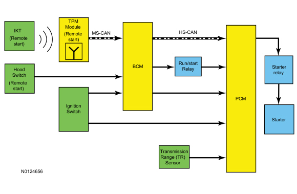
The starter system controls the cranking of the engine. The starter motor is enabled by the starter relay when the relay is activated by the PCM. The PCM receives inputs from the ignition switch, BCM Run/start relay and TR sensor before activating the starter relay to crank the engine.
Remote Start
The remote start feature allows the operator to remotely start the engine from up to 100 meters (328 feet) away and is activated using the IKT. Once started, the engine runs for 10 minutes. The run time can be extended by the operator.
System Operation
Network Message Chart
Network Input Messages BCM
Network Input Messages PCM
Starting System
NOTE: This vehicle is equipped with PATS that disables the engine from cranking and starting if an unprogrammed PATS key is used or an invalid PCM ID is received. PATS is controlled by the BCM. If there is a PATS concern that causes the engine to be disabled, the IPC displays "STARTING SYSTEM FAULT" in the message center. For additional information, refer to PATS, Section 419-01B.
When the ignition is turned to START, the PCM receives the following inputs:
- Ignition switch request to crank the engine
- Run/start relay voltage
- PATS is enabled message
- Correct transaxle PARK or NEUTRAL input from the TR sensor
When the PCM receives the correct inputs, voltage and ground is supplied to the starter relay coil. The starter relay coil is energized causing the relay contacts to close providing voltage to the starter solenoid, allowing the starter motor to crank and start the engine.
The PCM disengages the starter once an engine RPM threshold is reached, a set crank time is exceeded or the ignition is turned OFF.
Remote Start
When equipped with remote start, a remote start event is initiated when the IKT transmits a remote start request signal to the TPM. The TPM sends a remote start request message to the BCM. The BCM sends a crank request message to the PCM. The factory equipped remote start system does not operate if the ignition is in the RUN/START position or the hood is not closed.
The remote start system allows the operator to start the engine from up to 100 meters (328 feet) away, by pressing a sequence of buttons on the IKT. The remote start system is activated by pressing the lock button on the IKT once to make sure the doors are locked, followed by 2 presses of the remote start button. The 3 button presses must occur within 3 seconds of each other. The BCM acknowledges the remote start request by flashing the exterior lights twice. Once started, the engine runs for 10 minutes (default run time is 10 minutes; the time can be programmed by the customer to 5, 10 or 15 minutes) and the parking lights remain illuminated until the cycle is complete. The remote start duration can also be extended by initiating remote start while the first timer is still running or by initiating a completely independent start cycle when the first has completed. No more than 2 remote start sequences can occur within a one hour period, unless the ignition is set to the RUN/START position between the remote start requests. During the remote start cycle the power windows are inhibited and the radio will not turn on automatically but may be turned on manually from inside the vehicle. If the remote start system fails to start the horn chirps twice.
To transition from remote start mode to drive mode, use a programmed IKT to switch the ignition to the RUN position. If a programmed IKT is not used, the engine shuts off.
To deactivate the remote start system, press the remote start button once. When deactivating the remote start system the parking lights turn off to give a visual indication that the engine and climate control features have turned off. It may be necessary to be closer to the vehicle to deactivate the remote start feature than it was to initiate it due to ground deflections and added noise from the engine running.
Component Description
IKT
The RKE system uses an IKT. The IKT incorporates both the PATS and RKE functions into a single device. The factory installed remote start (if equipped), is controlled by the IKT function and allows the engine to be started from outside the vehicle. The RKE functions control the door lock/unlock features.
Passive Anti-Theft Transceiver
For additional information, refer to Section 419-01B.
BCM
The BCM is the gateway module, translating messages on the HS-CAN to MS-CAN. This allows a message to be distributed throughout both networks.
Ignition Switch
The ignition switch is controlled by the ignition lock cylinder with a key. When the ignition lock cylinder is turned using the key, a mechanical connection positions the ignition switch to the selected position and allows the ignition switch to send voltage to specific components. The ignition switch sends voltage to the BCM and PCM during engine cranking.
PCM
The PCM receives input signals from sensors and other components (switches, relays). Based on this information, the PCM generates output signals to control various relays, solenoids and actuators.
TPM Module
The TPM module is a receiving antenna that receives high frequency signals. When a remote start request is initiated from the IKT the TPM module receives the signal and communicates that remote start request message via the MS-CAN to the BCM to initiate a remote start event.
TR Sensor
The TR sensor is located inside the transaxle and indicates gearshift position to the PCM. The PCM uses that information to enable the starting system to start the engine in PARK or NEUTRAL. For additional information, refer to Section 307-01A or Section 307-01B.
Starting System - with Push Button Start
Overview
The starter system controls the cranking of the engine. The starter motor is enabled by the starter relay when the relay is activated by the PCM. The PCM receives inputs from the Start/stop switch, BCM, Run/start relay and TR sensor before activating the starter relay to crank the engine
Remote Start
The remote start feature allows the operator to remotely start the engine from up to 100 meters (328 feet) away and is activated using the IA key. Once started, the engine runs for 10 minutes. The run time can be extended by the operator.
System Operation
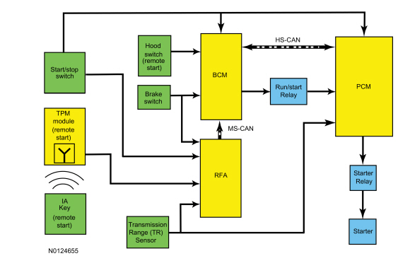
System Diagram
Network Message Chart
Module Network Input Messages RFA

Network Input Messages BCM
Network Input Messages PCM
Starting System
NOTE: This vehicle is equipped with PATS that disables the engine from cranking and starting if an unprogrammed PATS key is used or an invalid PCM ID is received. PATS is controlled by the BCM. If there is a PATS concern that causes the engine to be disabled, the IPC displays "STARTING SYSTEM FAULT" in the message center. For additional information, refer to PATS, Section 419-01C.
The RFA module in conjunction with the BCM controls the ignition modes and in conjunction with the PCM controls the starting system.
During a start event, the start/stop switch is pressed in combination with the brake pedal, the RFA module, PCM and BCM receive a request to start the engine. The PCM requires input voltage from the Run/start relay.
The PCM recognizes the correct inputs from the BCM and TR sensor and provides voltage and ground to energize the starter relay coil and close the starter relay contacts. The starter relay contacts close, providing voltage to the starter solenoid, allowing the starter motor to crank the engine. The PCM disengages the starter motor once an engine RPM threshold is reached, a set crank time is exceeded or the start/stop button is pressed indicating an engine shutdown request.
Remote Start
When equipped with remote start, a remote start event is initiated by pressing a sequence of buttons on the IA key. The factory equipped remote start system does not operate if the ignition is in the RUN/START position or the hood is not closed.
The remote start system allows the operator to start the engine from up to 100 meters (328 feet) away and is activated by pressing the lock button on the IA key once to make sure the doors are locked, followed by 2 presses of the remote start button. The 3 button presses must occur within 3 seconds of each other. The system acknowledges the start request by flashing the exterior lights twice. Once started, the engine runs for 10 minutes (default run time is 10 minutes; the time can be programmed by the customer to 5, 10 or 15 minutes) and the parking lights remain illuminated until the cycle is complete. The remote start duration can also be extended by initiating remote start while the first timer is still running or by initiating a completely independent start cycle when the first has completed. No more than 2 remote start sequences can occur within a one hour period, unless the ignition is set to the RUN/START position between the remote start requests. During the remote start cycle the power windows are inhibited and the radio will not turn on automatically but may be turned on manually from inside the vehicle. If the remote start system fails to start the horn will chirp twice.
To transition from remote start mode to drive mode, use a programmed IA key to transition to RUN. If a programmed IA key is not used, the engine shuts off.
To deactivate the remote start system, press the remote start button once. When deactivating the remote start system the parking lights turn off to give a visual indication that the engine and climate control features have turned off. It may be necessary to be closer to the vehicle to deactivate the remote start feature than it was to initiate it due to ground deflections and added noise from the engine running.
Component Description
BCM
The BCM is the gateway module, translating messages on the HS-CAN to MS-CAN. This allows a message to be distributed throughout both networks.
IA key
The IA key incorporates both the PATS and the RKE transmitter functions in a single device. The IA key must be located inside the vehicle for engine starting. When the IA key is activated it sends out a frequency signal that is received by the TPM module. The IA key also contains a key blade that is used to enter the vehicle as a backup.
Start-Stop Switch
The start/stop switch is a momentary contact switch that is hardwired to the RFA module, BCM, and PCM. When the switch is pressed, it signals the RFA module, BCM and PCM there is a request to either switch the ignition on or start the engine. The start/stop switch is connected to both modules as a backup in case of a failure. If there is a circuit failure to either module from the start/stop switch, the modules communicate the start/stop switch request to each other over the MS-CAN.
RFA module
The RFA module interprets radio frequency signals from the TPM module and IA key transmitters. The RFA module receives input signals from various modules and other components. Based on this information, the RFA module generates an output signal to control various components such as the door locks and the liftgate.
PCM
The PCM receives input signals from sensors and other components (switches, relays). Based on this information, the PCM generates output signals to control various relays, solenoids and actuators.
TPM Module
The TPM module is a receiving antenna that receives high frequency signals. When a remote start request is initiated from the IA key the TPM module receives the signal and communicates the remote start request message to the RFA module. The RFA module transmits the message via the MS-CAN to the BCM to initiate a remote start event.
TR Sensor
The TR sensor is located inside the transaxle and indicates gearshift position to the PCM. The PCM uses that information to enable the starting system to start the engine in PARK or NEUTRAL. For additional information, refer to Section 307-01A or Section 307-01B.
DIAGNOSIS AND TESTING
Starting System
Special Tool(s)
Inspection and Verification
Diagnostics in this manual assume a certain skill level and knowledge of Ford-specific diagnostic practices. Refer to Section 100-00 for information regarding Ford-specific diagnostic practices.
- Verify the customer concern by operating the starting system.
- Check the battery condition and state of charge. Refer to Section 414-01.
- Remove the accessory drive belt. Refer to Section 303-05. Verify the crankshaft and each of the components driven by the accessory drive belt rotate and are not seized or damaged.
- If any aftermarket accessories have been added to the vehicle, make sure they are properly wired.
- If an obvious cause for an observed or reported concern is found, correct the cause before proceeding.
DTC Charts
Diagnostics in this manual assume a certain skill level and knowledge of Ford-specific diagnostic practices. Refer to Diagnostic Methods in Section 100-00 for information about these practices.
RFA DTC Chart
NOTE: Any push-button start system fault results in DTCs being stored in the RFA module and BCM. Correct all RFA module DTCs prior to diagnosing the BCM DTCs.
PCM DTC Chart
BCM DTC Chart
TPM DTC Chart
Symptom Chart
Diagnostics in this manual assume a certain skill level and knowledge of Ford-specific diagnostic practices. Refer to Diagnostic Methods in Section 100-00 for information about these practices.
Pinpoint Tests
Pinpoint Test A: The Engine Does Not Crank (Without Push Button Start)
Diagnostic Overview
Diagnostics in this manual assume a certain skill level and knowledge of Ford-specific diagnostic practices. Refer to Diagnostic Methods in Section 100-00 for information about these practices.
Refer to Wiring Diagrams Cell 20, Starting System for schematic and connector information.
Normal Operation and Fault Conditions
The BCM and PCM receive a request to crank the engine when the ignition switch is turned to the START position. When the PCM receives the correct inputs from the BCM, voltage from the Run/start relay, and notification from the TR sensor that the gear selector is in PARK or NEUTRAL, the PCM then supplies voltage and ground to the starter relay coil. The energized coil causes the starter relay contacts to close. This allows voltage to be supplied from the BJB to the starter solenoid coil. The starter solenoid coil is grounded at the starter motor. Energizing the starter solenoid closes the solenoid contacts allowing voltage directly from the battery to the starter motor, engaging the starter drive into the ring gear causing the engine to crank. The PCM disengages the starter motor once an engine Revolutions Per Minute (RPM) threshold is reached, a set crank time is exceeded or the ignition switch has been turned to the OFF position.
-
Possible Sources
- Battery
- Battery cables
- Fuses
- High current BJB connections
- Ignition switch
- PCM
- Starter motor
- Starter motor bolts
- Wiring, terminals or connectors
-
Visual Inspection and Diagnostic Pre-checks
- Inspect the Run/start relay.
- Inspect the Starter relay.
- Verify the BJB fuse 19 (30A).
- Verify the BCM fuse 18 (10A).
- Verify the BCM fuse 26 (5A).
- Inspect the IKT.
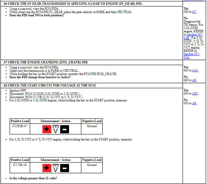
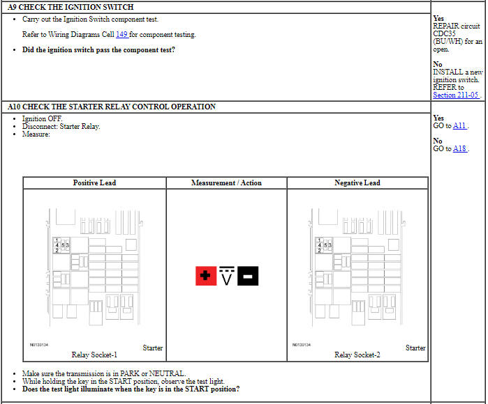
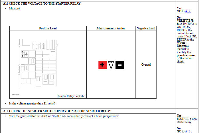
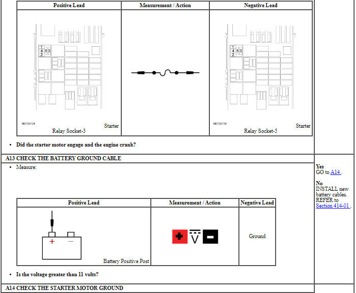
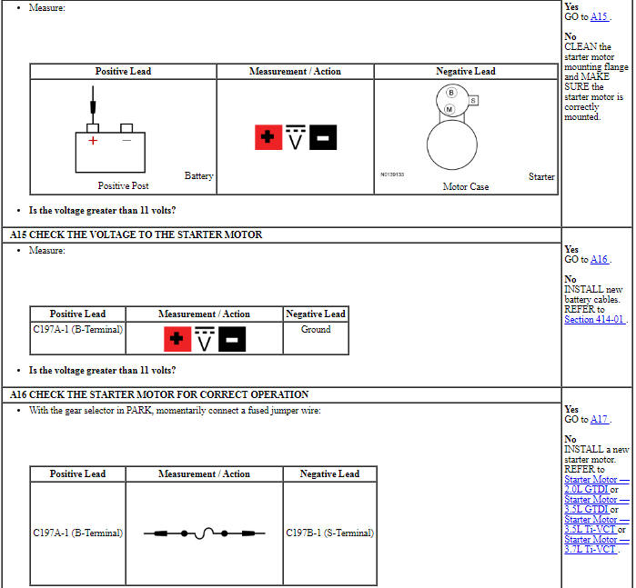
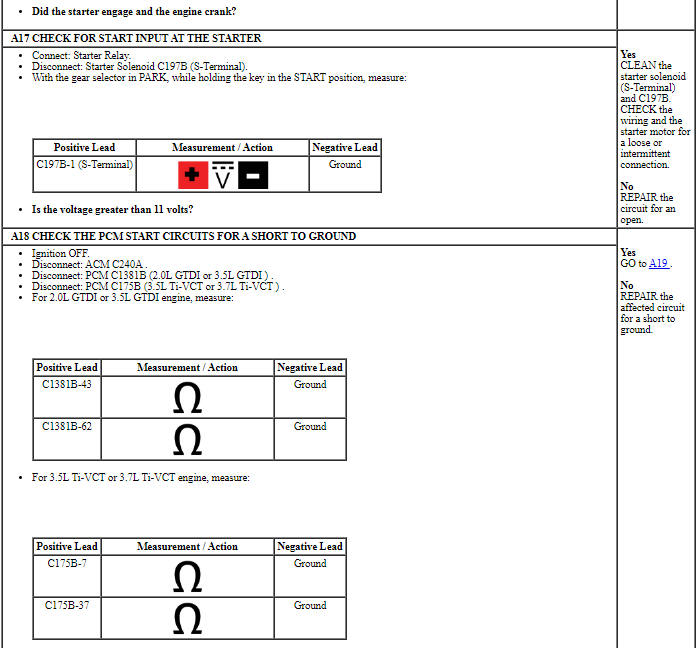
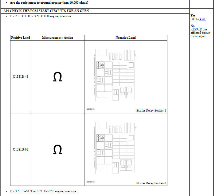
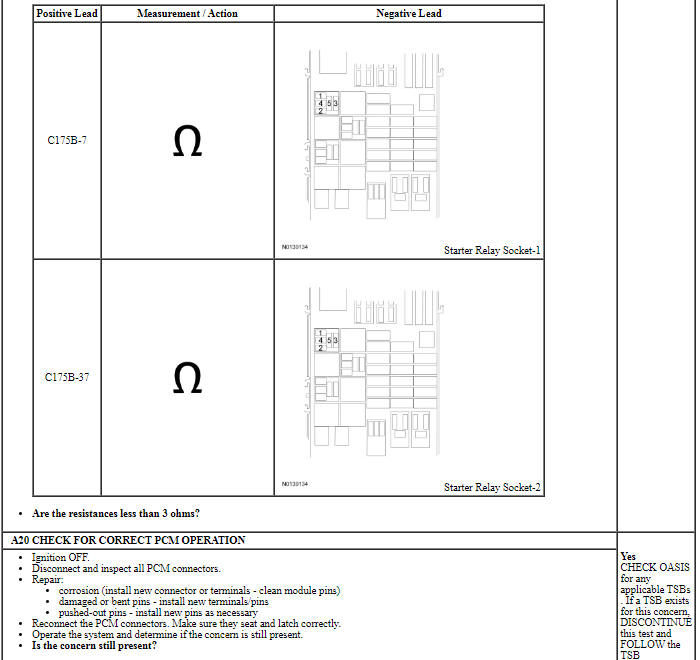
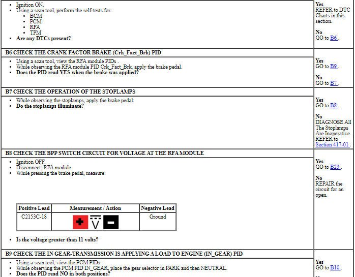
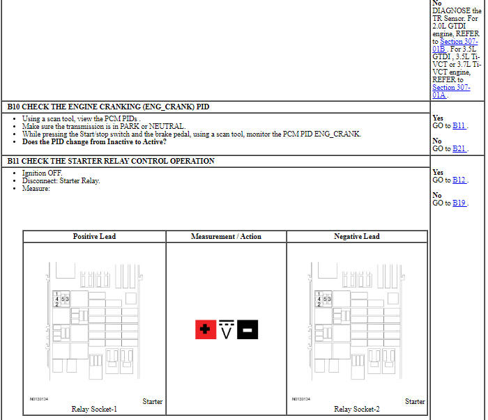
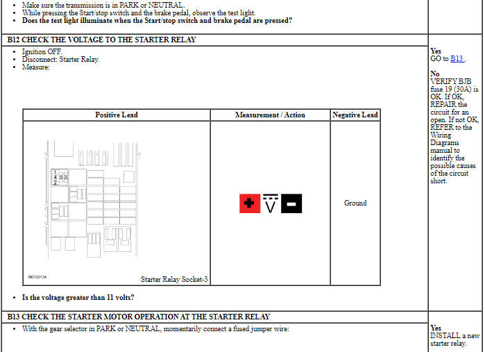
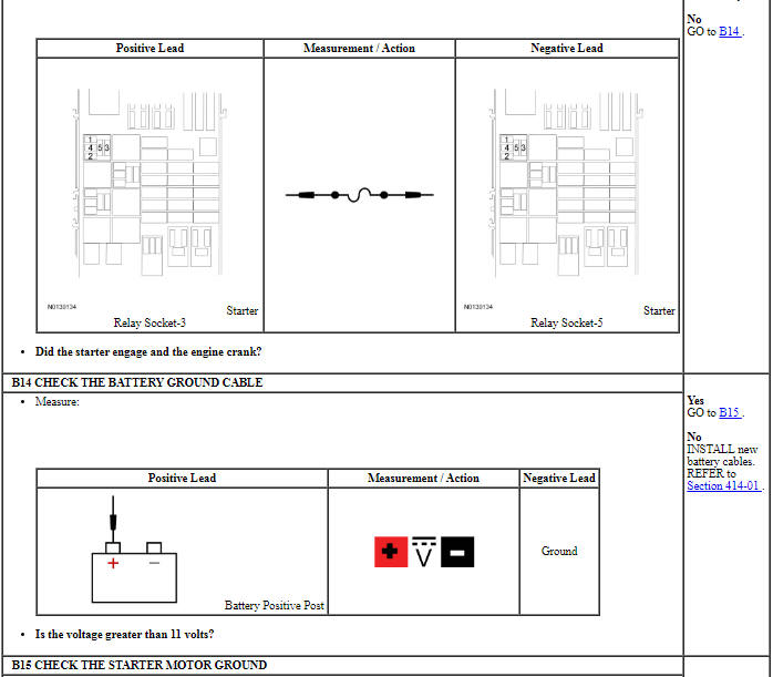
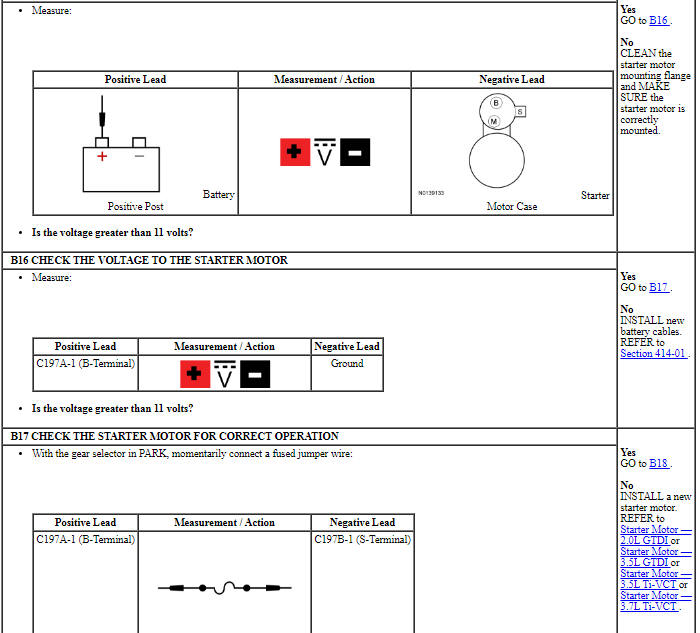
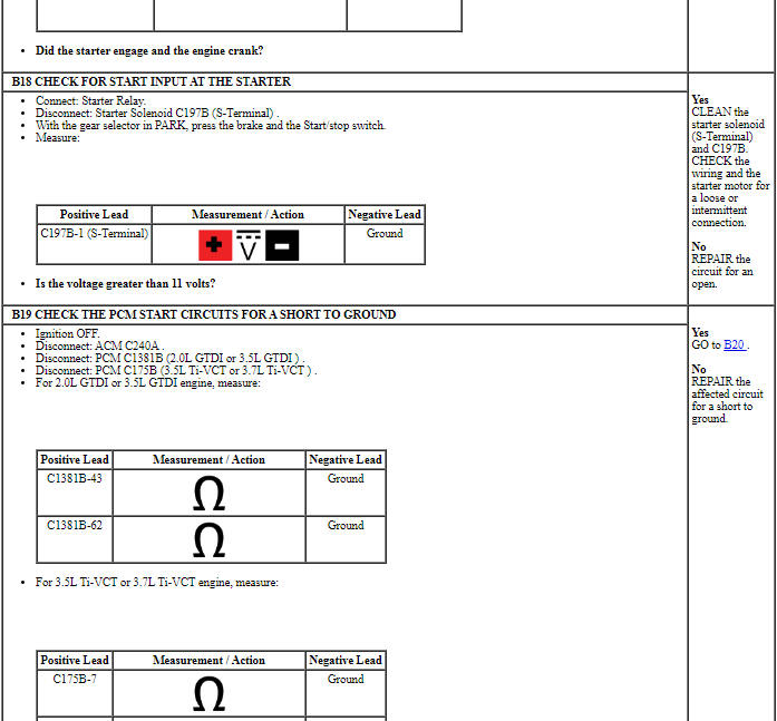
PINPOINT TEST A: ENGINE DOES NOT CRANK (WITHOUT PUSH BUTTON START)
Pinpoint Test B: The Engine Does Not Crank - With Push Button Start
Diagnostic Overview
Diagnostics in this manual assume a certain skill level and knowledge of Ford-specific diagnostic practices. Refer to Diagnostic Methods in Section 100-00 for information about these practices.
Refer to Wiring Diagrams Cell 20, Starting System for schematic and connector information.
Refer to Wiring Diagrams Cell 90, Turn Signal/ Stop/ Hazard Lamps for schematic and connector information.
Normal Operation and Fault Conditions
When the Start/stop switch is pressed in combination with the brake pedal, the RFA, BCM and PCM receive signals requesting to crank and start the engine. The PCM and RFA module receive notification from the TR sensor that the gear selector is in PARK or NEUTRAL. The PCM requires a voltage signal from the Run/start relay to operate. The PCM then supplies voltage and ground to the starter relay coil. The energized coil causes the starter relay contacts to close which allows voltage to be supplied from the BJB to the starter solenoid coil. The starter solenoid coil is grounded at the starter motor. Energizing the starter solenoid closes the solenoid contacts allowing voltage directly from the battery to the starter motor, engaging the starter drive into the ring gear causing the engine to crank. The PCM disengages the starter motor once an engine Revolutions Per Minute (RPM) threshold is reached, a set crank time is exceeded or the Start/stop switch is pressed indicating an engine shutdown request.
-
Possible Sources
- Battery
- Battery cables
- Fuses
- High current BJB connections
- Start/stop switch
- PCM
- Starter motor
- Starter motor bolts
- Wiring, terminals or connectors
-
Visual Inspection and Diagnostic Pre-checks
- Inspect the Run/start relay.
- Inspect the Starter relay.
- Verify the BJB fuse 19 (30A).
- Verify the BCM fuse 18 (10A).
- Verify the BCM fuse 26 (5A).
- Inspect the IA Key.
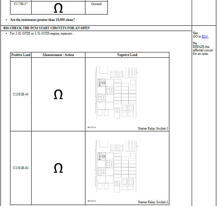
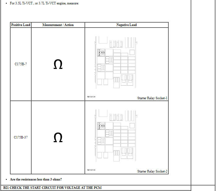
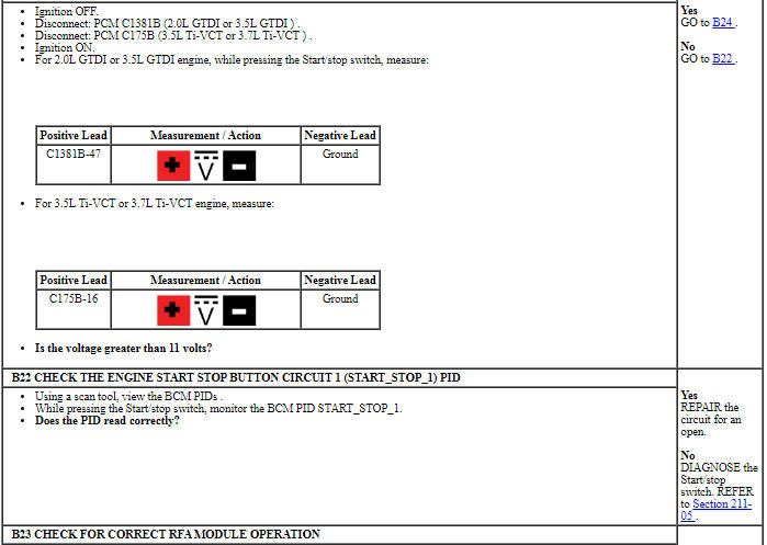
PINPOINT TEST B: ENGINE DOES NOT CRANK (WITH PUSH BUTTON START)
Pinpoint Test C: Unusual Starter Noise
Diagnostic Overview
Diagnostics in this manual assume a certain skill level and knowledge of Ford-specific diagnostic practices. Refer to Diagnostic Methods in Section 100-00 for information about these practices.
-
Normal Operation and Fault Conditions
- Starter motor
- Starter motor mounting
- Starter motor engagement
- Flexplate ring gear
PINPOINT TEST C: UNUSUAL STARTER NOISE
Pinpoint Test D: DTC C113A:11 OR C113A:15
Diagnostic Overview
Diagnostics in this manual assume a certain skill level and knowledge of Ford-specific diagnostic practices. Refer to Diagnostic Methods in Section 100-00 for information about these practices.
Refer to Wiring Diagrams Cell 112, Passive Anti-Theft System for schematic and connector information.
Normal Operation and Fault Conditions
The wake up control circuit is used to wake up the PCM prior to engine cranking. The PCM needs to wake up prior to a crank request so that it has time to go through its own initialization. The wake up control circuit also powers the Passive Anti-Theft System (PATS) transceiver (if equipped). The wake up control circuit is controlled by the Body Control Module (BCM) and receives voltage from fuse 18 (10A).
The BCM activates the wake up control circuit when:
- the driver door is opened.
- a remote start request is received (if equipped with factory remote start).
- the brake pedal is pressed.
- a key is inserted into the ignition.
- the ignition is in the RUN or START position.
- the start/stop switch is pressed, (if equipped with Intelligent Access (IA) )
Fault Trigger Conditions
-
Possible Sources
- BCM
- BCM Fuse 18 (10A)
- PATS transceiver (if equipped)
- PCM
- Wiring, terminals or connectors
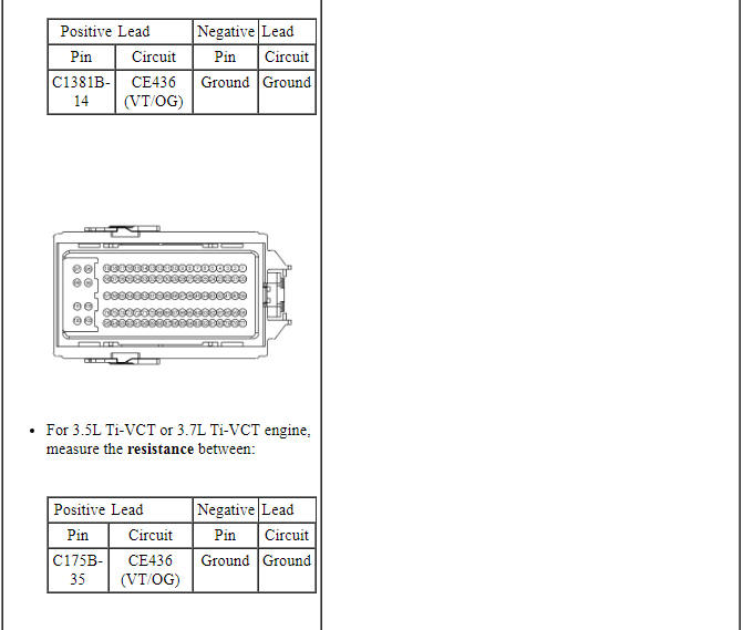
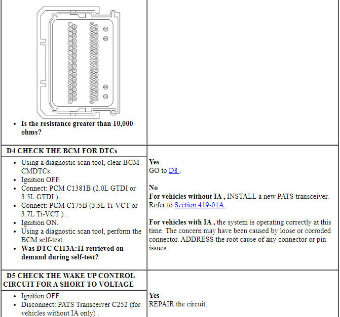
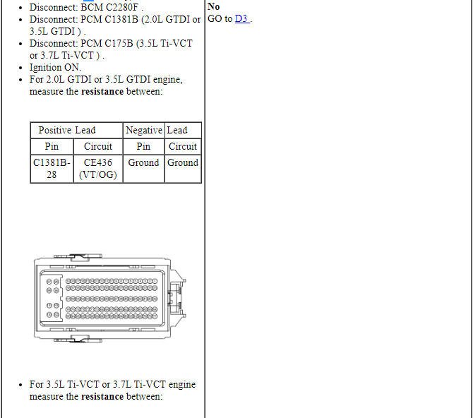
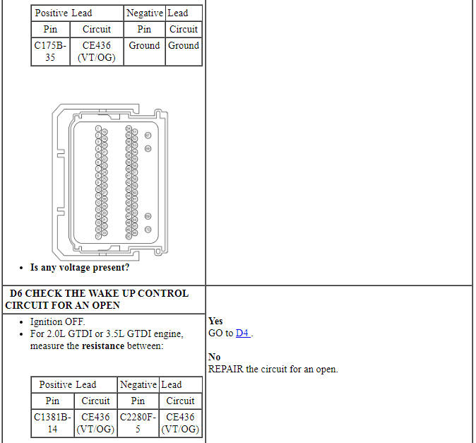
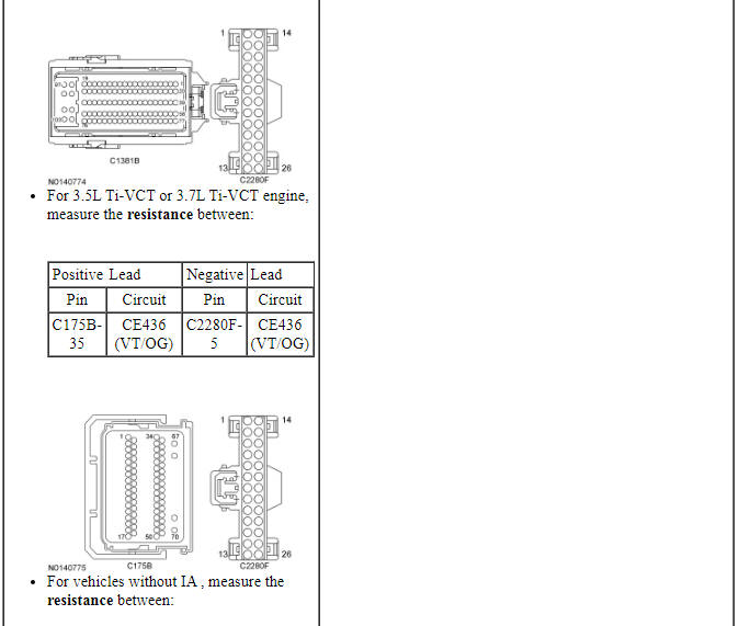
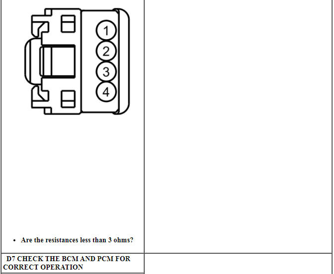
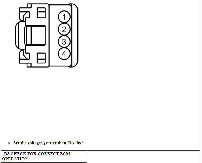
PINPOINT TEST D: DTC C113A:11 OR C113A:15
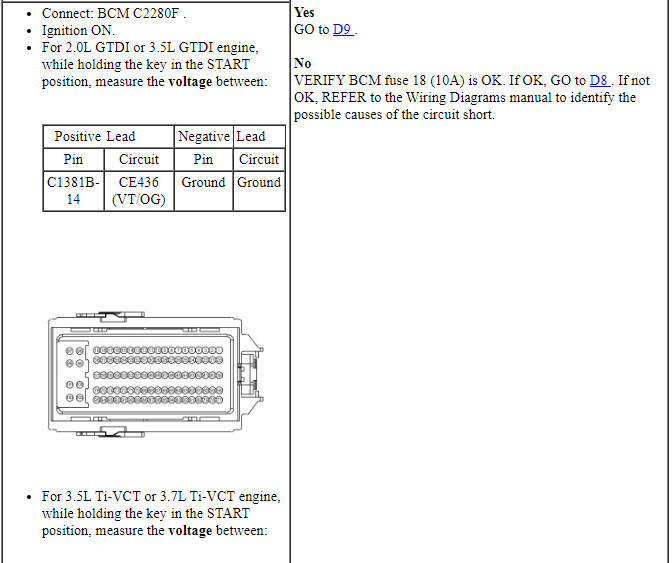
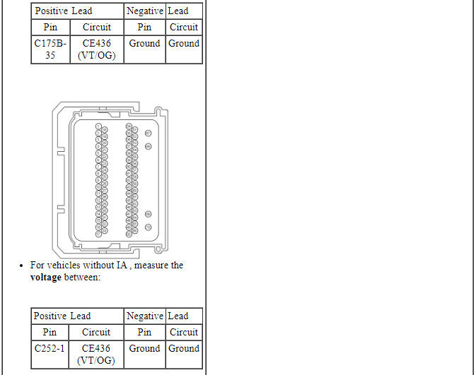
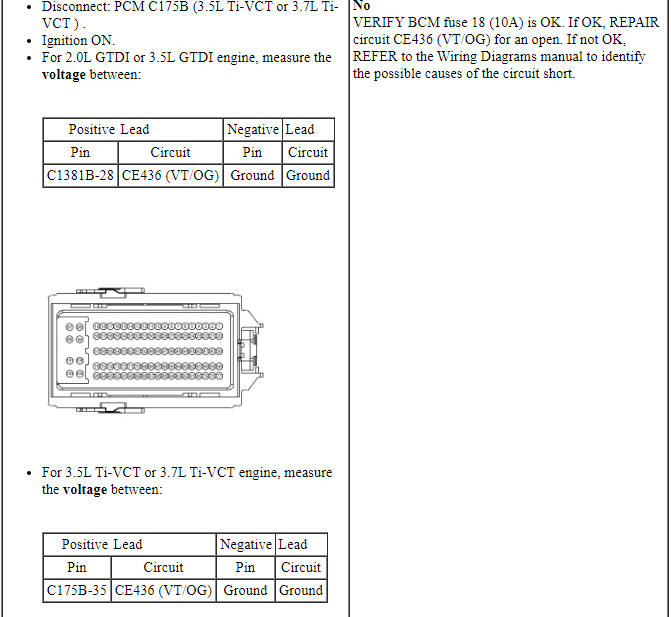
NOTICE: Use the correct probe adapter(s) when making measurements. Failure to use the correct probe adapter(s) may damage the connector.
Pinpoint Test E: DTC B1D55:01
Diagnostic Overview
Diagnostics in this manual assume a certain skill level and knowledge of Ford-specific diagnostic practices. Refer to Diagnostic Methods in Section 100-00 for information about these practices.
Normal Operation and Fault Conditions
An external antenna connected to the Tire Pressure Monitor Module (TPM) receives a signal from the Integrated Keyhead Transmitter (IKT) or Intelligent Access (IA) key to enable activation of the remote start function from a distance of up to 100 meters (328 feet). If the external antenna fails, the remote start operates with a reduction in the range of operation.
Fault Trigger Conditions
-
Possible Sources
- External antenna
- External antenna lead
- TPM
- Wiring, terminals or connectors
PINPOINT TEST E: DTC B1D55:01
Pinpoint test F: The Remote Start Is Inoperative
Diagnostic Overview
Diagnostics in this manual assume a certain skill level and knowledge of Ford-specific diagnostic practices. Refer to Diagnostic Methods in Section 100-00 for information about these practices.
Normal Operation and Fault Conditions
The factory equipped remote start system enables the engine to be started from up to 100 meters (328 feet) away by pressing the Integrated Keyhead Transmitter (IKT) or Intelligent Access (IA) key lock button followed by 2 presses of the remote start button. The 3 button presses must occur within 3 seconds. The IKT or IA key signal is received through an external antenna attached to the Tire Pressure Monitor Module (TPM) and communicated over the Medium Speed Controller Area Network (MS-CAN) to initiate the vehicle start.
-
Possible Sources
- Wiring, terminals or connectors
- Remote start feature enabled
- IKT (vehicles without IA )
- IA key (vehicles with IA )
- External antenna
- Hood switch input
- PCM
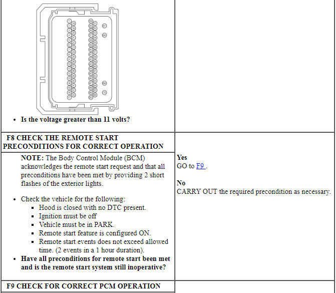
PINPOINT TEST F: THE REMOTE START IS INOPERATIVE
Component Tests
WARNING: Before beginning any service procedure in this section, refer to Safety Warnings in Section 100-00. Failure to follow this instruction may result in serious personal injury.
WARNING: Always disconnect the battery ground cable at the battery before disconnecting the starter motor battery terminal lead. If a tool is shorted at the starter motor battery terminal, the tool can quickly heat enough to cause a skin burn. Failure to follow this instruction may result in serious personal injury.
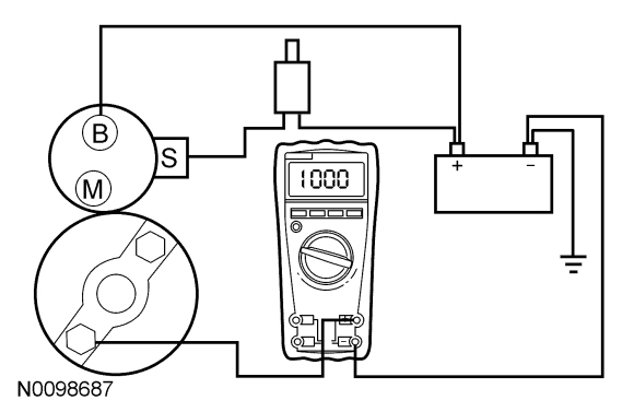
Always make the Fluke 77-IV Digital Multimeter connections at the component terminal rather than at the wiring end connector. Making a connection at the wiring end connector could result in false readings because the meter will not pick up a high resistance between the wiring connector and the component.
Starter Motor - Feed Circuit Test
- Make sure the battery is fully charged. Refer to Section 414-01.
- Carry out a battery drain test. Refer to Section 414-01.
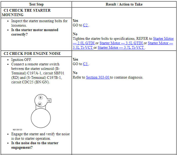
- Connect a remote starter switch between starter solenoid S-Terminal and the battery positive terminal.
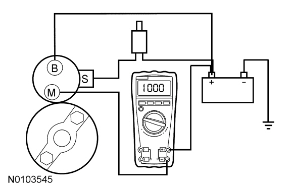
- Connect the Digital Multimeter positive lead to the battery positive post. Connect the negative lead to the starter solenoid "M" terminal.
- Place the gear select lever in Park or Neutral.
- Engage the remote starter switch. Read and record the voltage. The voltage reading should be 0.5 volt or less.
- If the voltage reading is 0.5 volt or less, go to the Starter Motor - Ground Circuit Test in this section.
- A voltage reading greater than 0.5 volt is an indication of excessive resistance in the starter connections, the positive battery cable or in the starter solenoid. Remove the cables from solenoid "B", "S", and "M" terminals. Clean the cable connections and reinstall the cables to the correct terminals. Repeat Steps 3 through 7.
- If the voltage reading is still greater than 0.5 volt when checked at the "M" terminal, move the Digital Multimeter negative lead to the starter solenoid B-Terminal and repeat step 6.
- If the voltage reading at the B-Terminal is lower than 0.5 volt, the concern is in the connections at the starter solenoid or in the solenoid contacts. Install a new starter motor. Refer to Starter Motor - 2.0L GTDI or Starter Motor - 3.5L GTDI or Starter Motor - 3.5L Ti-VCT or Starter Motor - 3.7L Ti-VCT.
- If the voltage reading taken at the solenoid B-Terminal is still greater than 0.5 volt after cleaning the cables and connections at the solenoid, the concern is either in the positive battery cable connection or in the positive battery cable itself.
- Clean the positive battery cable connections. If this does not solve the problem, install a new positive battery cable. Refer to Section 414-01.
Starter Motor - Ground Circuit Test
WARNING: Before beginning any service procedure in this section, refer to Safety Warnings in Section 100-00. Failure to follow this instruction may result in serious personal injury.
A slow cranking condition can be caused by resistance in the ground or return portion of the cranking circuit. Check the voltage drop in the ground circuit as follows:
- Connect a remote starter switch between starter solenoid S-Terminal and the battery positive terminal.
- Connect the Digital Multimeter positive lead to the starter motor housing (the connection must be clean and free of rust or grease). Connect the negative lead to the negative battery terminal.
- Place the gear select lever in Park or Neutral.
- Engage the remote starter switch and crank the engine. Read and record the voltage reading. The reading should be 0.5 volt or less.
- If the voltage drop is greater than 0.5 volt, clean the negative cable connections at the battery, the body ground connections and the starter ground connection. Retest.
- If the voltage drop is greater than 0.5 volt, install new battery cables. Refer to Section 414-01. If the voltage reading is less than 0.5 volt and the engine still cranks slowly, install a new starter motor. Refer to Starter Motor - 2.0L GTDI or Starter Motor - 3.5L GTDI or Starter Motor - 3.5L Ti-VCT or Starter Motor - 3.7L Ti-VCT.
GENERAL PROCEDURES
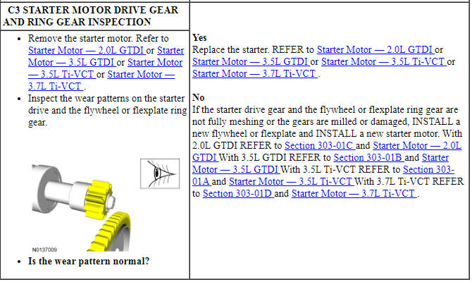
Starter Motor Drive Gear and Flywheel Ring Gear Inspection
- Remove the starter motor, refer to Starter Motor - 2.0L GTDI, Starter Motor - 3.5L Ti-VCT, Starter Motor - 3.5L GTDI or Starter Motor - 3.7L Ti-VCT.
- Check the wear patterns on the starter drive gear and the flexplate ring gear. If the wear pattern is normal, install the starter motor, refer to Starter Motor - 2.0L GTDI, Starter Motor - 3.5L Ti-VCT, Starter Motor - 3.5L GTDI or Starter Motor - 3.7L Ti-VCT.
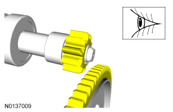
- If the starter drive gear and the flexplate ring gear are not fully
meshing and both of the gears are scored or damaged, install a new starter
motor, refer to Starter Motor - 2.0L GTDI, Starter Motor - 3.5L Ti-VCT, Starter
Motor - 3.5L GTDI or Starter Motor - 3.7L Ti-VCT.
If necessary, install a new flexplate, refer to Section 303-01A, Section 303-01B, Section 303-01C or Section 303-01D.
REMOVAL AND INSTALLATION
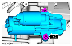
Starter Motor - 2.0L GTDI
Removal and Installation
WARNING: Always disconnect the battery ground cable at the battery before disconnecting the starter motor battery terminal lead. If a tool is shorted at the starter motor battery terminal, the tool can quickly heat enough to cause a skin burn. Failure to follow this instruction may result in serious personal injury.
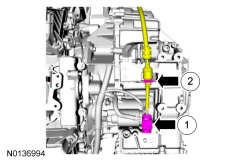
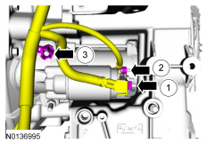
- NOTE: Removal steps in this procedure may contain installation
details.
Disconnect the battery ground cable. For additional information, refer to Section 414-01.
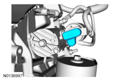
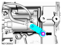
- NOTE: It will be necessary to position the coolant hoses as
needed to remove the starter motor.
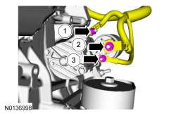
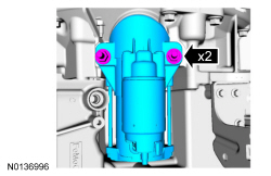
- Tighten to 18 Nm (159 lb-in).
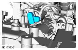
- Tighten to 12 Nm (106 lb-in).
- Tighten to 5 Nm (44 lb-in).
-
- Tighten to 48 Nm (35 lb-ft).
- NOTE: Inspect the starter drive gear and the flexplate ring gear.
For additional information, refer to Starter Motor Drive Gear and Flywheel
Ring Gear Inspection in this section.
To install, reverse the removal procedure.
Starter Motor - 3.5L GTDI
Removal and Installation
WARNING: Always disconnect the battery ground cable at the battery before disconnecting the starter motor battery terminal lead. If a tool is shorted at the starter motor battery terminal, the tool can quickly heat enough to cause a skin burn. Failure to follow this instruction may result in serious personal injury.
NOTE: Removal steps in this procedure may contain installation details.
- Disconnect the battery ground cable. For additional information, refer to Section 414-01.
- Remove the Air Cleaner (ACL) assembly. For additional information, refer to Section 303-12.

-
- Tighten to 18 Nm (159 lb-in).
-
- Tighten to 12 Nm (106 lb-in).
- Tighten to 5 Nm (44 lb-in).

-
- Tighten to 48 Nm (35 lb-ft).
- NOTE: Inspect the starter drive gear and the flexplate ring gear.
For additional information, refer to Starter Motor Drive Gear and Flywheel
Ring Gear Inspection in this section.
To install, reverse the removal procedure.
Starter Motor - 3.5L Ti-VCT
Removal and Installation
WARNING: Always disconnect the battery ground cable at the battery before disconnecting the starter motor battery terminal lead. If a tool is shorted at the starter motor battery terminal, the tool can quickly heat enough to cause a skin burn. Failure to follow this instruction may result in serious personal injury.
NOTE: Removal steps in this procedure may contain installation details.
- Disconnect the battery ground cable. For additional information, refer to Section 414-01.
- Remove the Air Cleaner (ACL) assembly. For additional information, refer to Section 303-12.

-
- Tighten to 18 Nm (159 lb-in).


-
- Tighten to 12 Nm (106 lb-in).
- Tighten to 5 Nm (44 lb-in).

-
- Tighten to 48 Nm (35 lb-ft).

- NOTE: Inspect the starter drive gear and the flexplate ring gear.
For additional information, refer to Starter Motor Drive Gear and Flywheel
Ring Gear Inspection in this section.
To install, reverse the removal procedure.
Starter Motor - 3.7L Ti-VCT
Removal and Installation
WARNING: Always disconnect the battery ground cable at the battery before disconnecting the starter motor battery terminal lead. If a tool is shorted at the starter motor battery terminal, the tool can quickly heat enough to cause a skin burn. Failure to follow this instruction may result in serious personal injury.
NOTE: Removal steps in this procedure may contain installation details.
- Disconnect the battery ground cable. For additional information, refer to Section 414-01.
- Remove the Air Cleaner (ACL) assembly. For additional information, refer to Section 303-12.
-
- Tighten to 18 Nm (159 lb-in).


-
- Tighten to 12 Nm (106 lb-in).
- Tighten to 5 Nm (44 lb-in).
-
- Tighten to 48 Nm (35 lb-ft).

- NOTE: Inspect the starter drive gear and the flexplate ring gear.
For additional information, refer to Starter Motor Drive Gear and Flywheel
Ring Gear Inspection in this section.
To install, reverse the removal procedure.
 Accessory Drive
SPECIFICATIONS
Torque Specifications
DESCRIPTION AND OPERATION
Accessory Drive
Component Location
2.0L GTDI
3.5L TiVCT, 3.7L TiVCT and 3.5L GTDI
Overview
The accessory drive system provides power ...
 Engine Ignition - 3.5L Ti-VCT
SPECIFICATIONS
Material
General Specifications
Torque Specifications
DESCRIPTION AND OPERATION
Engine Ignition
Component Location
System Operation
REFER to the PC/ED manual
section 1 D ...
Other materials:
Module Communications Network
DESCRIPTION AND OPERATION
Communications Network
Overview
Multiplexing is a method of sending 2 or more signals simultaneously on the
same network circuits. Multiplexing is used to allow 2 or more electronic
modules (nodes) to communicate simultaneously over a twisted-wire pair [data (+)
and data ...
Getting the services you need
Warranty repairs to your vehicle must be performed by an authorized
dealer. While any authorized dealer handling your vehicle line will
provide warranty service, we recommend you return to your selling
authorized dealer who wants to ensure your continued satisfaction.
Please note that certain ...
Exterior Trim and Ornamentation
SPECIFICATIONS
Torque Specifications
REMOVAL AND INSTALLATION
Applique - Luggage Compartment Lid
Removal and Installation
NOTE: Removal steps in this procedure may contain installation
details.
To install, tighten to 5 Nm (44 lb-in).
If equipped.
To ...
