Generator - 2.0L GTDI
Removal
- Disconnect the battery. For additional information, refer to Section 414-01.
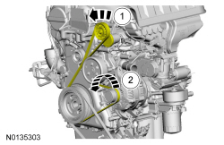
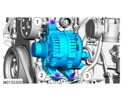
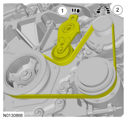
- Remove the upper Charge Air Cooler (CAC) pipe. For additional information, refer to Intake Air System Components - Exploded View in Section 303-12.
Installation
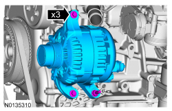
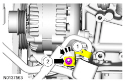
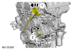
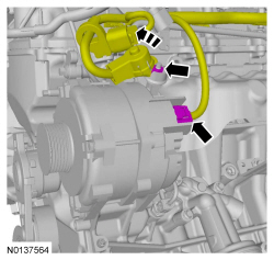
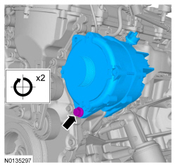
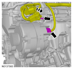
- Position the generator and hand-tighten the 3 bolts. Tighten in the
sequence shown.
- Tighten to 25 Nm (18 lb-ft).
-
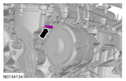
- Tighten to 15 Nm (133 lb-in).
-
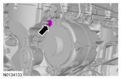
- Tighten to 17 Nm (150 lb-in).

- Install the upper Charge Air Cooler (CAC) pipe. For additional information, refer to Intake Air System Components - Exploded View in Section 303-12.
- Connect the battery. For additional information, refer to Section 414-01.
Generator - 3.5L GTDI, 3.5L Ti-VCT, 3.7L Ti-VCT
Removal
All vehicles
- Disconnect the battery. For additional information, refer to Section 414-01.
Radial arm removal only
NOTE: If equipped, the radial arm adapter is a serviceable item. Do not remove the generator if the radial arm adapter is the only concern.
Vehicles equipped with a 3.5L Ti-VCT or 3.7L Ti-VCT engine
- Remove the cooling fan assembly. For additional information, refer to Section 303-03.
Vehicles equipped with a 3.5L GTDI engine
- Remove the A/C compressor. For additional information, refer to Section 412-01.
All vehicles


Installation
Radial arm installation only
-
- Tighten to 9 Nm (80 lb-in).
- Tighten to 17 Nm (150 lb-in).
All vehicles
-
- Tighten to 8 Nm (71 lb-in).
-
- Tighten to 47 Nm (35 lb-ft).
-
- Tighten to 47 Nm (35 lb-ft).
-
- Tighten to 17 Nm (150 lb-in).
Vehicles equipped with a 3.5L GTDI engine
- Install the A/C compressor. For additional information, refer to Section 412-01.
Vehicles equipped with a 3.5L Ti-VCT or 3.7L Ti-VCT engine
- Install the cooling fan assembly. For additional information, refer to Section 303-03.
All vehicles
- Connect the battery cable. For additional information, refer to Section 414-01.
Generator Clutch
Removal
NOTE: This procedure only applies to the 2.0L GTDI.
- Remove the generator. Refer to Generator - 2.0L GTDI.
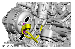
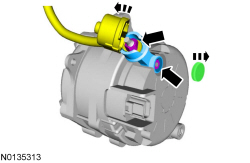
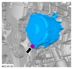
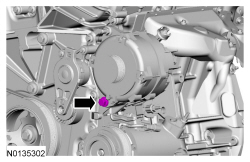
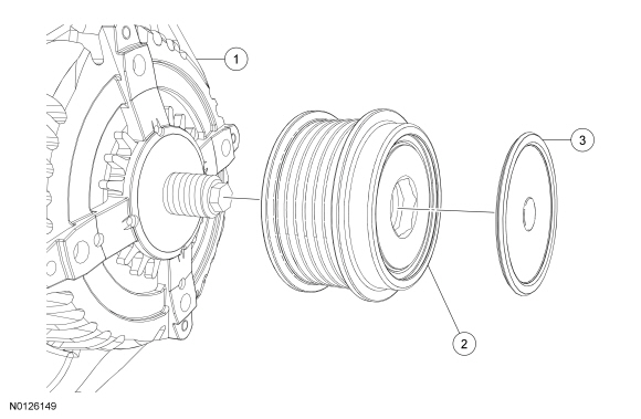
- Using a small screwdriver or similar tool, insert the tool through the soft rubber area on the center of the pulley cap and pry off the cap. Discard the cap.
- NOTICE: Do not insert anything into the fins of the generator
to prevent the rotor inside the generator from turning. Inserting items into
the generator could result in damage to the generator.
NOTE: The shaft and rotor will turn during removal.
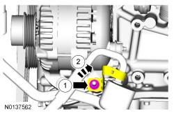
Insert a 17 mm hex tool into the clutch pulley. Install an impact gun onto the hex tool and use the impact gun to remove the clutch pulley. A couple of short bursts with the impact gun will remove the clutch pulley.
Installation
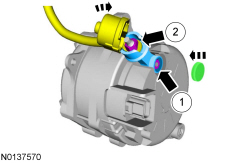
- Hand start the clutch pulley onto the generator shaft.
- Insert a 17 mm hex tool into the clutch pulley and install a 17 mm, 55 lb-ft torque stick on the hex tool.
- NOTICE: Do not insert anything into the fins of the generator
to prevent the rotor inside the generator from turning. Inserting items into
the generator could result in damage to the generator.
NOTE: The shaft and rotor will turn during installation.
While holding the outer diameter of the clutch pulley, torque the clutch pulley using the impact gun and the 17 mm, 55 lb-ft torque stick for 3-4 seconds. This makes sure the proper torque has been applied.- Tighten to 75 Nm (55 lb-ft).
- Install a new cap onto the pulley with the rubber button facing inwards.
- Install the generator. Refer to Generator - 2.0L GTDI.
 Diagnosis and Testing
Charging System
Special Tool(s)
DTC Charts
Diagnostics in this manual assume a certain skill level and knowledge of
Ford-specific diagnostic practices. REFER to Diagnostic Methods in Section ...
 Battery, Mounting and Cables
SPECIFICATIONS
General Specifications
Torque Specifications
DESCRIPTION AND OPERATION
Battery and Cables
Overview
The battery and cable system consists of the following components:
Battery
...
Other materials:
Fuel Tank and Lines
SPECIFICATIONS
General Specifications
Torque Specifications
DESCRIPTION AND OPERATION
Fuel Tank and Lines
2.0L Gasoline Turbocharged Direct Injection (GTDI)
Fuel Tank and Lines
The fuel tank and lines consists of:
a single container (L-shaped) fuel tank.
a fuel level sensor assembly.
a Fuel ...
Safety precautions
WARNING: Do not overfill the fuel tank. The pressure in an
overfilled tank may cause leakage and lead to fuel spray and fire.
WARNING: The fuel system may be under pressure. If you hear
a hissing sound near the fuel filler inlet, do not refuel until the
sound stops. Otherwise, fuel may spray out ...
Engine coolant check
Checking the Engine Coolant
The concentration and level of engine coolant should be checked at the
intervals listed in Scheduled Maintenance Information.
Note: Make sure that the level is at the FULL COLD level or within the
COLD FILL RANGE in the coolant reservoir.
Note: Coolant expands wh ...
