SPECIFICATIONS
General Specifications
Torque Specifications
DESCRIPTION AND OPERATION
Battery and Cables
Overview
The battery and cable system consists of the following components:
- Battery
- Battery cable assembly (both negative and positive cable serviced as an assembly)
- High current BJB
- Battery current sensor
- Generator current sensor
- Battery tray
The battery has 3 major functions:
- Engine cranking power source
- Voltage stabilizer for the electrical system
- Temporary power source when electrical loads exceed the generator output current
Battery Eye Operation
The battery eye indicates the state-of-charge of the battery by responding to the specific gravity of a single battery cell electrolyte. The battery eye has a viewing plate, 2 colored balls of different specific gravity and a small passage. As the state-of-charge and specific gravity changes, the balls change their position in the passageway and subsequently display a different color in the viewing eye. The primary purpose of the battery eye is to be a quick indicator of state-of-charge for assembly plants and dealership pre-delivery processes.
The color of the battery eye indicates the approximate state-of-charge.
- Red - indicates low state-of-charge.
- Yellow/Black - indicates between high and low state-of-charge.
- Green - indicates high state-of-charge.
- No color can occur after the battery has been in service for several years and some of the plate material has coated the balls.
- A clear battery eye can occur if the battery case becomes damaged and the electrolyte has fallen below the plates.
NOTE: The battery eye can remain red for a period of time (up to several days), even after the battery is fully charged, because the acid is not yet fully mixed.
Do not install a new battery based solely on the indication of the battery eye. The battery eye color simply indicates the battery state-of-charge, not its condition. For example, a red or yellow/black battery eye usually indicates the battery is discharged, not defective. If the battery eye indicates the battery may be discharged, it is necessary to recharge the battery before testing its condition.
Component Description
Battery
Vehicles are equipped with a 12-volt, maintenance-free battery.
Ford Motor Company strongly recommends that lead-acid batteries be returned to an authorized recycling facility for disposal.

DIAGNOSIS AND TESTING
Battery
Special Tool(s)
Pinpoint Test A: Battery Condition Test
Diagnostic Overview
Diagnostics in this manual assume a certain skill level and knowledge of Ford-specific diagnostic practices. Refer to Diagnostic Methods in Section 100-00 for more information.
Normal Operation
Battery condition is determined by measuring battery terminal voltage after a specific discharge current is applied for a specified time period.
-
Visual Inspection and Diagnostic Pre-checks
- Inspect wiring, terminals and connectors
- Inspect the battery
- Inspect battery mounting
- Inspect high current BJB connections
PINPOINT TEST A: BATTERY CONDITION TEST
GENERAL PROCEDURES
Battery Disconnect
WARNING: Batteries contain sulfuric acid and produce explosive gases. Work in a well-ventilated area. Do not allow the battery to come in contact with flames, sparks or burning substances. Avoid contact with skin, eyes or clothing. Shield eyes when working near the battery to protect against possible splashing of acid solution. In case of acid contact with skin or eyes, flush immediately with water for a minimum of 15 minutes, then get prompt medical attention. If acid is swallowed, call a physician immediately. Failure to follow these instructions may result in serious personal injury.
WARNING: Always deplete the backup power supply before repairing or installing any new front or side air bag supplemental restraint system (SRS) component and before servicing, removing, installing, adjusting or striking components near the front or side impact sensors or the restraints control module (RCM). Nearby components include doors, instrument panel, console, door latches, strikers, seats and hood latches. Refer to the Description and Operation portion of Section 501-20B for location of the RCM and impact sensor(s). To deplete the backup power supply energy, disconnect the battery ground cable and wait at least 1 minute. Be sure to disconnect auxiliary batteries and power supplies (if equipped). Failure to follow these instructions may result in serious personal injury or death in the event of an accidental deployment.
WARNING: Always lift a plastic-cased battery with a battery carrier or with hands on opposite corners. Excessive pressure on the battery end walls may cause acid to flow through the vent caps, resulting in personal injury and/or damage to the vehicle or battery.
WARNING: Battery posts, terminals and related accessories contain lead and lead components. Wash hands after handling. Failure to follow these instructions may result in serious personal injury.
NOTE: When the battery (or PCM) is disconnected and connected, some abnormal drive symptoms may occur while the vehicle relearns its adaptive strategy. The charging system set point may also vary. The vehicle may need to be driven to relearn its strategy.
- NOTE: When disconnecting the battery cable to interrupt power to
the vehicle electrical system, disconnect the battery ground cable only. It
is not necessary to disconnect the positive battery cable.
Loosen the battery cable terminal nut and disconnect the battery ground terminal.
- To connect, tighten to 9 Nm (80 lb-in).
- Loosen the battery cable terminal nut and disconnect the positive
battery terminal.
- To connect, tighten to 9 Nm (80 lb-in).
- To connect, reverse the disconnect procedure.
Battery Drain Test
WARNING: Batteries contain sulfuric acid and produce explosive gases. Work in a well-ventilated area. Do not allow the battery to come in contact with flames, sparks or burning substances. Avoid contact with skin, eyes or clothing. Shield eyes when working near the battery to protect against possible splashing of acid solution. In case of acid contact with skin or eyes, flush immediately with water for a minimum of 15 minutes, then get prompt medical attention. If acid is swallowed, call a physician immediately. Failure to follow these instructions may result in serious personal injury.
NOTE: No factory-equipped vehicle should have more than a 50 mA (0.050 amp) draw.
NOTE: Many electronic modules draw 10 mA (0.010 amp) or more continuously.
NOTE: Typically, a drain of approximately 1 amp is attributed to an engine compartment lamp, glove compartment lamp or interior lamp staying on continually. Other component failures or wiring shorts are located by selectively pulling fuses to pinpoint the location of the current drain. When the current drain is found, the meter reading falls to an acceptable level. If the drain is still not located after checking all the fuses, it may be due to the generator. Disconnect the generator and retest.
NOTE: To accurately test the drain on a battery, an in-line ammeter must be used between the negative battery post and its respective cable. Use of a test lamp or voltmeter is not an accurate method.
- Make sure the junction box(es)/fuse panel(s) is accessible without turning on the interior lights or the underhood lights.
- Drive the vehicle at least 5 minutes and over 48 km/h (30 mph) to turn on and activate the vehicle systems.
- Allow the vehicle to sit with the key out of the ignition for at least 40 minutes to allow the modules to time out/power down.
- Connect a fused jumper wire (30A) between the negative battery cable and the negative battery post to prevent modules from resetting.
- Disconnect the negative battery cable from the negative battery post without breaking the connection of the jumper wire.
- NOTICE: To prevent damage to the meter, do not crank the
engine or operate accessories that draw more than 10A.
NOTE: It is very important that continuity is not broken between the battery and the negative battery cable when connecting the meter. If this happens, the entire 40-minute procedure must be repeated.
Connect the battery tester between the negative battery cable and the post. The meter must be capable of reading milliamps and should have a 10-amp capability.
- NOTE: If the meter settings need to be switched or the test leads
need to be moved to another jack, the jumper wire must be reinstalled to
avoid breaking continuity.
Remove the jumper wire.
- Note the amperage draw. Draw varies from vehicle to vehicle depending on the equipment package. Compare to a similar vehicle for reference.
NOTE: If the vehicle sits for an extended period of time and the battery drains, there is the possibility of a control module staying alive and not going into sleep mode. If a module does stay alive, it can also result in battery drain. If a module is suspect, isolate individual modules by disconnecting each module one at a time and note if the excessive draw goes away.
NOTE: For vehicles equipped with aftermarket bodies or boxes which contain electrical connections, disconnect the aftermarket to factory connections to isolate the body from the chassis.
- If the current draw is excessive, remove the fuses from the BJB one at a
time and note the current drop. When the current level drops to an
acceptable level after removing a fuse, the circuit containing the excessive
draw has been located. The excessive draw can be isolated by continuing to
pull sub system fuses. Do not reinstall the fuses until testing is finished.
To correctly isolate each of the circuits, all of the fuses may need to be
removed, then install one fuse and note the amperage draw, remove the fuse
and install the next fuse. Continue this process with each fuse.
- Once the main circuit is identified, continue to remove the fuses from the SJB one at a time and note the current reading. Do not reinstall the fuses until testing is finished. To correctly isolate each of the circuits, all of the fuses may need to be removed, then install one fuse and note the amperage draw, remove the fuse and install the next fuse. Continue this process with each fuse.
- Check the wiring diagrams for any circuits that run from the battery without passing through the BJB or the SJB. If the current draw is still excessive, disconnect these circuits until the draw is found. Also, disconnect the generator electrical connections and retest if the draw cannot be located. The generator may be internally shorted, causing the current drain.
Battery Charging
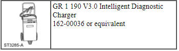
Special Tool(s)
Battery Charging Overview
NOTE: Batteries discharge while the vehicle is on the dealer lot or parked by the customer for an extended period of time due to normal parasitic key-off loads. Also, vehicles still in dealer inventory or in long-term storage may be driven short distances with heavy electrical loads. Over a period of time (30 days or more), this could result in vehicles having shallow or deeply discharged batteries.
The vehicle charging system is designed to supply the electrical power needed to maintain the battery near full charge during normal vehicle use. The charging system is not capable of bringing a deeply discharged battery back to near full charge in a short amount of time such as allowing the vehicle to idle for 15 minutes to "recharge the battery." Discharged batteries should be charged using an external charger.
NOTE: Battery chargers have improved greatly with the addition of the new generation pulse chargers. These chargers pulse current into the battery, breaking down the sulfation layer on the battery plates and generally reduce charging times to less than an hour.
NOTE: Cold batteries will not readily accept a charge. Therefore, batteries should be allowed to warm to approximately 5ÂşC (41ÂşF) before charging. This may require 4 to 8 hours at room temperature.
- The following chart summarizes 2 recommended methods of charging.
a A deeply discharged is a battery that is drained over a
prolonged period of time, such as an unsold vehicle or a vehicle in storage,
to the point the battery is dead.
b A shallow discharged battery is a battery that is drained by
leaving an accessory on for several hours or a few days and has a very low
charge.
Charger Connected to Negative Battery Terminal
NOTE: When charging the vehicle battery by connecting the charger to the negative battery terminal is necessary, such as when using a combination battery charger and battery tester/analyzer, like the GR 1 190 V3.0 Intelligent Diagnostic Charger, the BCM will not immediately update the battery state of charge. In this instance, after charging, you must CARRY OUT the BMS Reset using the scan tool.
- Connect the positive (red) charger clamp to the positive battery post.
- Connect the negative (black) charger clamp to the negative battery post.
- Charge the battery according to the battery charger owner's literature.
- After charging is complete, carry out the BMS Reset using the scan tool.
Charger Connected to Engine or Chassis Ground
- Connect the positive (red) charger clamp to the positive battery post.
- NOTE: The negative charger clamp must be connected to an
unpainted chassis surface or a solid engine component such as a generator
mount or engine lifting eye.
Connect the negative (black) charger clamp to an engine or chassis ground.
- Charge the battery according to the battery charger owner's literature.
REMOVAL AND INSTALLATION
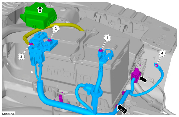
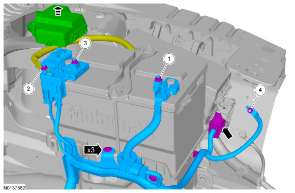
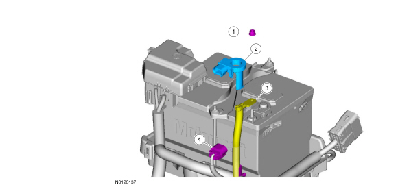
Battery and Battery Tray - Exploded View
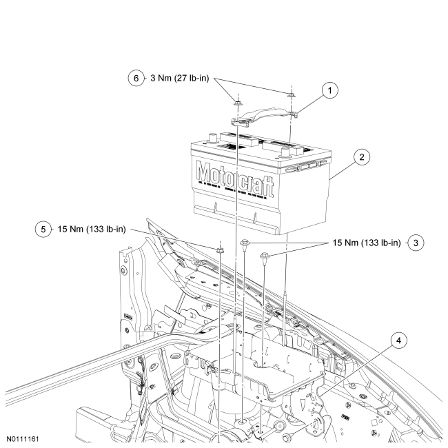
- For additional information, refer to the procedures in this section.
Battery
Removal and Installation
WARNING: Batteries contain sulfuric acid and produce explosive gases. Work in a well-ventilated area. Do not allow the battery to come in contact with flames, sparks or burning substances. Avoid contact with skin, eyes or clothing. Shield eyes when working near the battery to protect against possible splashing of acid solution. In case of acid contact with skin or eyes, flush immediately with water for a minimum of 15 minutes, then get prompt medical attention. If acid is swallowed, call a physician immediately. Failure to follow these instructions may result in serious personal injury.
WARNING: Always lift a plastic-cased battery with a battery carrier or with hands on opposite corners. Excessive pressure on the battery end walls may cause acid to flow through the vent caps, resulting in personal injury and/or damage to the vehicle or battery.
WARNING: When directed to drive the vehicle as part of this test, drive the vehicle on a hard surface in an area without traffic to prevent a crash. Failure to follow these instructions may result in personal injury.
- Disconnect the battery. For additional information, refer to Battery Disconnect in this section.
- Remove the 2 nuts and the battery hold-down clamp.
- To install, tighten to 3 Nm (27 lb-in).
- Remove the battery.
- To install, reverse the removal procedure.
- Carry out the BMS Reset using the scan tool after the battery is connected, if the battery has been replaced. If the BMS Reset is not carried out, it takes approximately 8 hours for the BCM to learn the new battery state of charge. During this 8 hour period, the vehicle must be undisturbed, with no doors opened or keyless entry button presses. If the vehicle is used before the BCM is allowed to learn the new battery state of charge, engine off load shedding can still occur and a message may be displayed.
Battery Tray
Removal and Installation
- Remove the battery. For additional information, refer to Battery in this section.
- Remove the Air Cleaner (ACL) assembly. For additional information, refer to Section 303-12.
- Disconnect the wiring harness fastener from the battery tray.
- Remove the 3 bolts and 1 nut from the battery tray.
- To install, tighten to 15 Nm (133 lb-in).
- Disconnect the Battery Junction Box (BJB) fastener and remove the battery tray.
- To install, reverse the removal procedure.
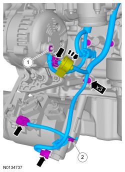
Battery Cables - 2.0L GTDI
Removal and Installation
-
- Tighten to 9 Nm (80 lb-in).
- Tighten to 9 Nm (80 lb-in).
- Tighten to 9 Nm (80 lb-in).
- Tighten to 8 Nm (71 lb-in).
-
- Tighten to 17 Nm (150 lb-in).
- Tighten to 25 Nm (18 lb-ft).
-
- Tighten to 12 Nm (106 lb-in).
- Tighten to 5 Nm (44 lb-in).
- Tighten to 17 Nm (150 lb-in).
-
- Tighten to 10 Nm (89 lb-in).
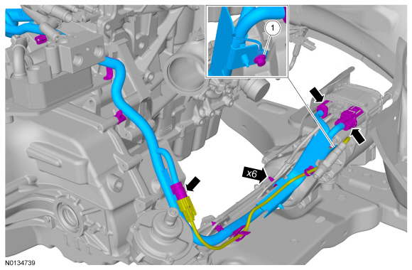
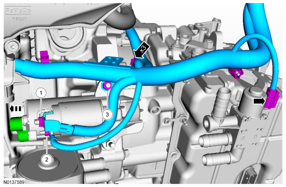
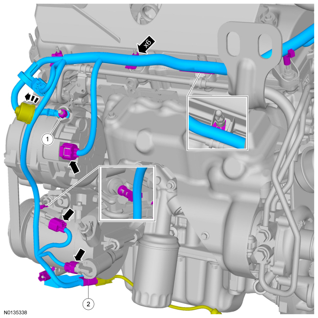
Battery Cables - 3.5L GTDI, 3.5L Ti-VCT, 3.7L Ti-VCT
Removal and Installation
-
- Tighten to 9 Nm (80 lb-in).
- Tighten to 9 Nm (80 lb-in).
- Tighten to 9 Nm (80 lb-in).
- Tighten to 8 Nm (71 lb-in).
- NOTE: 3.5L GTDI shown, all others similar.
- Tighten to 17 Nm (150 lb-in).
- If equipped, with 3.5L GTDI.
- NOTE: 3.5L GTDI shown, all others similar.
- Tighten to 12 Nm (106 lb-in).
- Tighten to 5 Nm (44 lb-in).
- Tighten to 15 Nm (133 lb-in).
- If equipped, with PTU cooler.
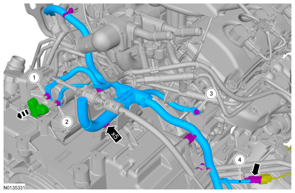
- NOTE: 3.5L GTDI shown, all others similar.
- If equipped, with 3.5L GTDI.
- Tighten to 10 Nm (89 lb-in).
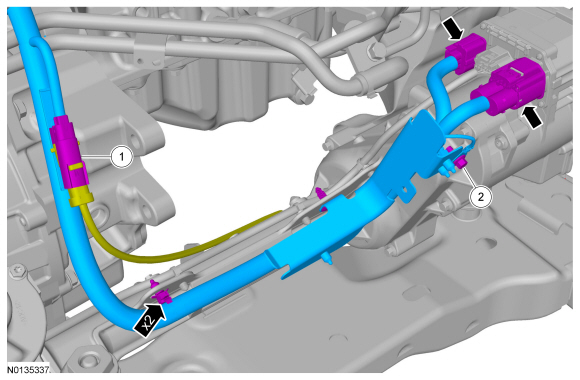
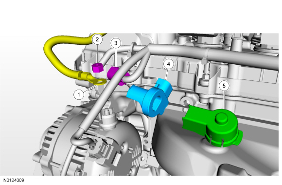
Battery Current Sensor
Removal
- Remove the nut and position the negative battery cable terminal aside.
- Remove the ACL outlet pipe and cover. For additional information, refer to Section 303-12.
- Disconnect the battery current sensor electrical connector.
- NOTE: Note the orientation and position of the battery current
sensor tape tab.
Index-mark the battery cable at the battery current sensor. Remove and discard the tape securing the battery current sensor to the battery cable and remove the battery current sensor.
Installation
- NOTE: The battery current sensor must be installed in the proper
position and orientation to function correctly.
With the battery current sensor tape tab pointing downward, position the battery current sensor to the index-mark on the battery cable and secure with electrical tape.
- Connect the battery current sensor electrical connector.
- Install the ACL outlet pipe and cover. For additional information, refer to Section 303-12.
- Connect the negative battery cable terminal to the battery terminal and
install the battery terminal nut.
- Tighten to 9 Nm (80 lb-in).
Generator Current Sensor
NOTE: 3.5L Ti-VCT shown, 2.0L GTDI and 3.5L GTDI similar.
Removal
- Disconnect the battery. For additional information, refer to Battery Disconnect in this section.
- Position the generator B+ terminal cover aside, remove the nut and position the generator B+ terminal aside.
- Remove the generator B+ terminal cover from the battery cable.
- Disconnect the generator current sensor electrical connector.
- NOTE: Note the orientation and position of the generator current
sensor tape tab.
Index-mark the battery cable at the generator current sensor. Remove and discard the tape securing the generator current sensor to the battery cable and remove the generator current sensor.
Installation
- NOTE: The generator current sensor must be installed in the
proper position and orientation to function correctly.
With the generator current sensor tape tab pointing upward, position the generator current sensor to the index-mark on the battery cable and secure with electrical tape.
- Connect the generator current sensor electrical connector.
- Install the generator B+ terminal cover to the battery cable.
- Connect the generator B+ terminal and install the nut. Position the
generator B+ terminal cover.
- Tighten to 17 Nm (150 lb-in).
- Connect the battery. For additional information, refer to Battery Disconnect in this section.
 Removal and Installation
Generator - 2.0L GTDI
Removal
Disconnect the battery. For additional information, refer to Section
414-01.
Remove the upper Charge Air Cooler (CAC) pipe. For additional
informati ...
 Audio Systems
...
Other materials:
Heated seats
WARNING: Persons who are unable to feel pain to the skin
because of advanced age, chronic illness, diabetes, spinal cord
injury, medication, alcohol use, exhaustion, or other physical conditions,
must exercise care when using the seat heater. The seat heater may
cause burns even at low temperatu ...
Capacities and Specifications
Engine Drivebelt Routing
3.5L V6 engine
3.5L V6 SHO engine
2.0L EcoBoost engine
...
Disassembly
Engine
Special Tool(s)
Material
NOTICE: During engine repair procedures, cleanliness is extremely
important. Any foreign material, including any material created while cleaning
gasket surfaces that enters the oil passages, coolant passages or the oil pan,
can cause engine failure.
NOTE:& ...
