Charging System
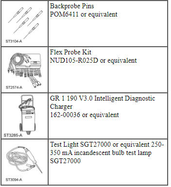
Special Tool(s)
DTC Charts
Diagnostics in this manual assume a certain skill level and knowledge of Ford-specific diagnostic practices. REFER to Diagnostic Methods in Section 100-00 for more information.
NOTE: The BCM utilizes a 5-character DTC followed by a 2-character failure-type code. The failure-type code provides information about specific fault conditions such as opens or shorts to ground. CMDTCs have an additional 2-character DTC status code suffix to assist in determining DTC history.
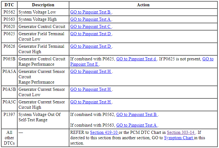
PCM DTC Chart
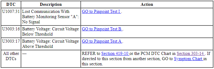
BCM DTC Chart
Symptom Chart
Diagnostics in this manual assume a certain skill level and knowledge of Ford-specific diagnostic practices. REFER to Diagnostic Methods in Section 100-00 for more information.
-
Preliminary Inspection
- Before diagnosing or repairing the charging
system inspect the following items:
- Fusible links
- Abnormal ignition-off current drain(s)
- Battery
- High current BJB for loose or corroded connections
- Radial arm adapter (if equipped)
- Wiring, terminals or connectors
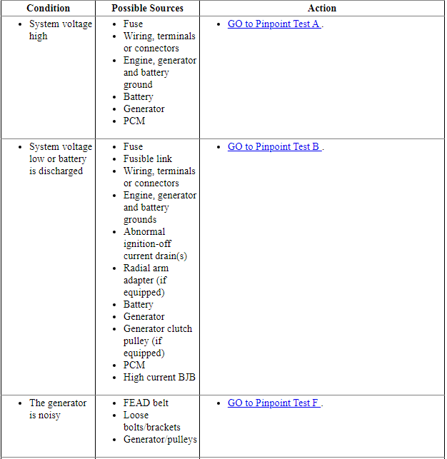
Symptom Chart - Charging System
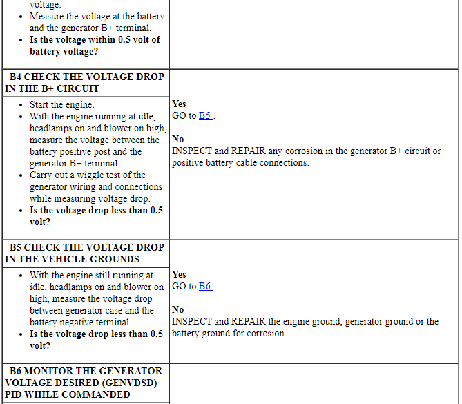
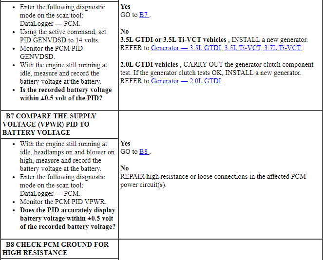
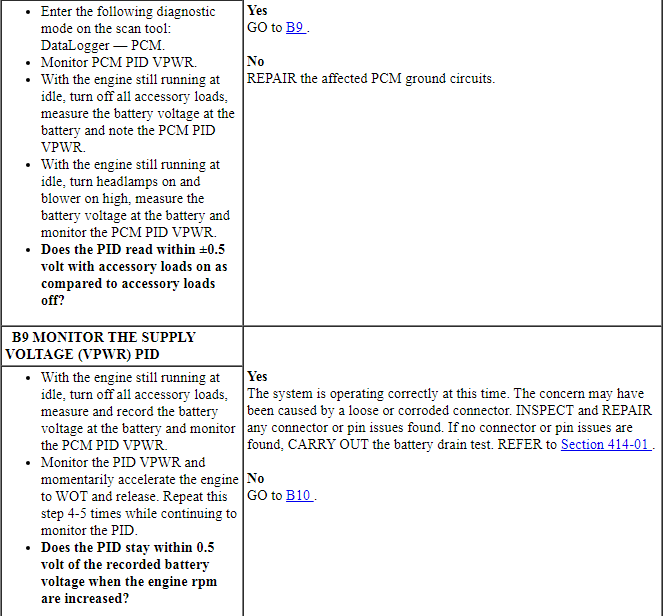
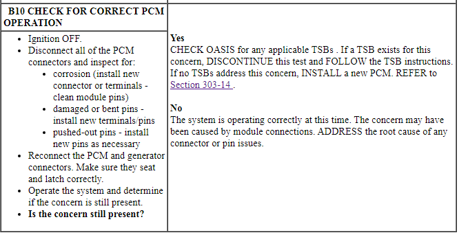
Pinpoint Tests
Pinpoint Test A: System Voltage High
Diagnostic Overview
Diagnostics in this manual assume a certain skill level and knowledge of Ford-specific diagnostic practices. Refer to Diagnostic Methods in Section 100-00 for more information.
Refer to Wiring Diagrams Cell 12, Charging System for schematic and connector information.
Normal Operation and Fault Conditions
With the engine running, the charging system supplies voltage to the battery and the vehicle electrical system through the high current BJB and battery B+ cable. The voltage that is supplied to the vehicle electrical system is used for the operation of the various vehicle systems and modules. Many modules monitor this voltage and if it rises above or below their calibrated setpoints, a DTC sets.
Visual Inspection and Diagnostic Pre-checks
Before diagnosing or repairing the charging system inspect the following items:
- Fusible links
- Wiring, terminals or connectors
- High current BJB for loose or corroded connections
NOTE: DTC P1397 can be set if the vehicle has been recently jump started, the battery has been recently charged or the battery has been discharged. The battery may become discharged due to excessive load(s) on the charging system from aftermarket accessories or if vehicle accessories have been operating for an extended period of time without the engine running.
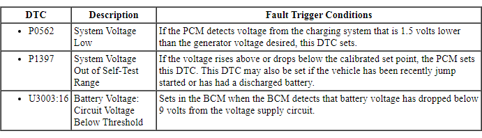
DTC Fault Trigger Conditions
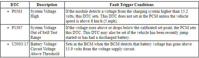
-
This pinpoint test is intended to diagnose the following:
- Fuse
- Wiring, terminals or connectors
- Engine, generator and battery grounds
- Battery
- Generator
- PCM
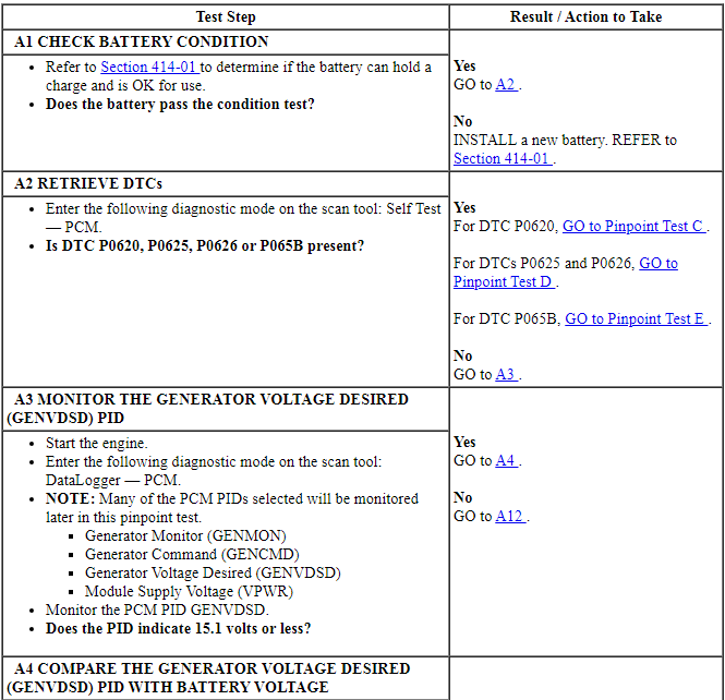
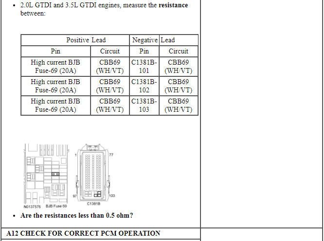
PINPOINT TEST A: SYSTEM VOLTAGE HIGH
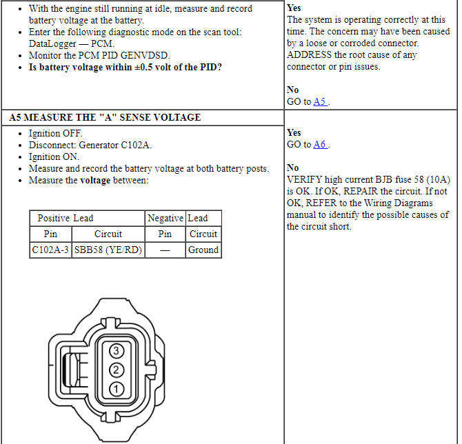
NOTE: Make sure battery voltage is greater than 12.2 volts prior to and during this pinpoint test.
NOTE: Do not have a battery charger attached during vehicle testing.
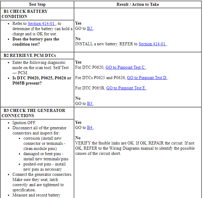
Pinpoint Test B: System Voltage Low or Battery is Discharged
Diagnostic Overview
Diagnostics in this manual assume a certain skill level and knowledge of Ford-specific diagnostic practices. Refer to Diagnostic Methods in Section 100-00 for more information.
Refer to Wiring Diagrams Cell 12, Charging System for schematic and connector information.
Normal Operation and Fault Conditions
With the engine running, the charging system supplies voltage to the battery and the vehicle electrical system through the battery B+ cable. The PCM monitors this voltage through the battery positive post through the high current BJB. If voltage drops 1.5 volts or more below the generator voltage desired, this DTC sets after 30 seconds.
Visual Inspection and Diagnostic Pre-checks
Before diagnosing or repairing the charging system inspect the following items:
- Fusible links
- Abnormal ignition-off current drain(s)
- Battery
- Wiring, terminals or connectors
- High current BJB for loose or corroded connections
- Radial arm adapter (if equipped)
NOTE: DTC P0562 or P1397 can be set if the vehicle has been recently jump started, the battery has been recently charged or the battery has been discharged. The battery may become discharged due to excessive load(s) on the charging system from aftermarket accessories or if vehicle accessories have been operating for an extended period of time without the engine running.
DTC Fault Trigger Conditions
-
This pinpoint test is intended to diagnose the following:
- Fuse
- Fusible link
- Wiring, terminals or connectors
- Engine, generator and battery grounds
- Abnormal ignition-off current drain(s)
- Radial arm adapter (if equipped)
- Battery
- Generator
- Generator clutch pulley (if equipped)
- PCM
- High current BJB
PINPOINT TEST B: SYSTEM VOLTAGE LOW OR BATTERY IS DISCHARGED
NOTE: Make sure battery voltage is greater than 12.2 volts prior to and during this pinpoint test.
NOTE: Do not have a battery charger attached during vehicle testing.
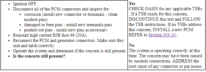
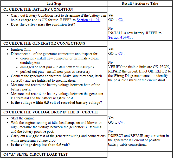
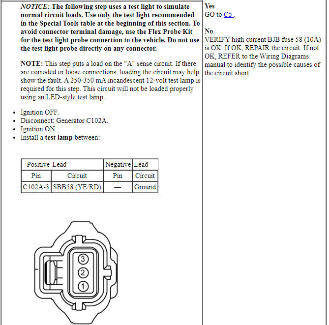
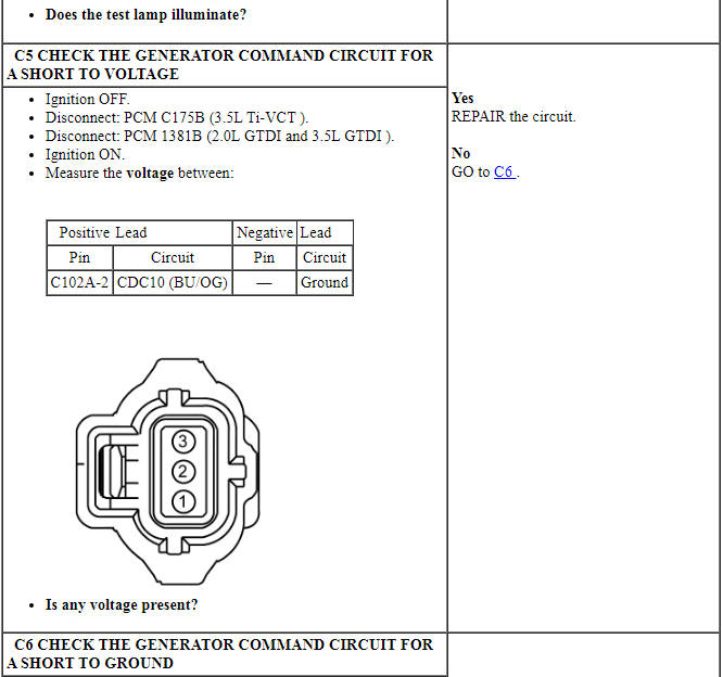
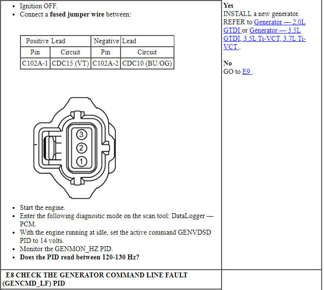
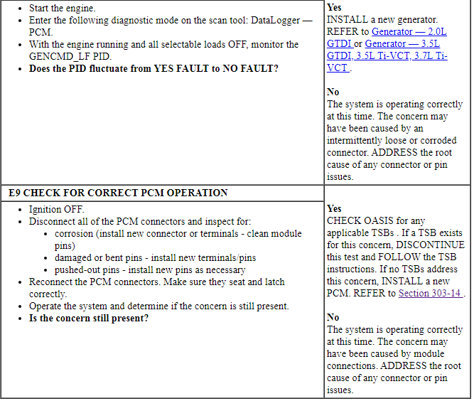
Pinpoint Test C: DTC P0620
Diagnostic Overview
Diagnostics in this manual assume a certain skill level and knowledge of Ford-specific diagnostic practices. Refer to Diagnostic Methods in Section 100-00 for more information.
Refer to Wiring Diagrams Cell 12, Charging System for schematic and connector information.
Normal Operation and Fault Conditions
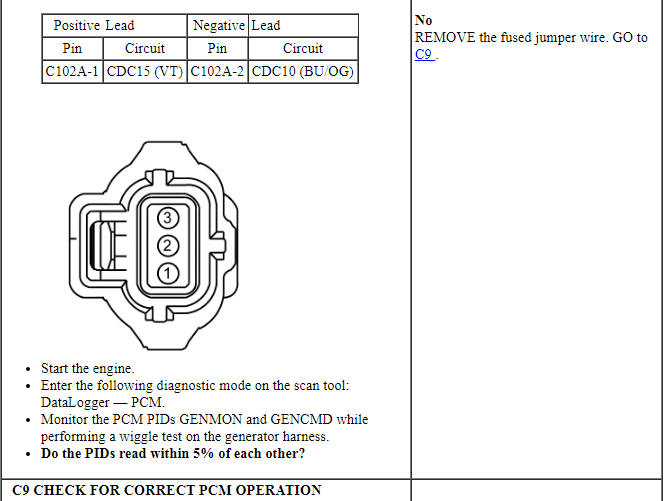
The PCM monitors the generator output via the generator monitor (GENMON) circuit. The PCM uses the generator command (GENCOM) circuit to command the generator to either increase or decrease output. If the GENCOM circuit (generator control circuit) or the "A" sense circuit are open or shorted to ground, the PCM will not be able to control the generator output. When the engine speed is greater than 2,000 rpm, the generator defaults to a steady voltage output of 13.5 volts and the PCM sends a request to the IPC to illuminate the charging system warning indicator. A GENCOM circuit fault can be confirmed by viewing the PCM PID generator command line fault (GENCMD_LF) (YES status indicator fault).
Visual Inspection and Diagnostic Pre-checks
Before diagnosing or repairing the charging system inspect the following items:
- Fusible links
- Wiring, terminals or connectors
- High current BJB for loose or corroded connections
- Radial arm adapter (if equipped)
DTC Fault Trigger Conditions
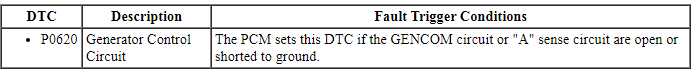
-
This pinpoint test is intended to diagnose the following:
- Fuse
- Wiring, terminals or connectors
- Generator
- PCM
- Radial arm adapter (if equipped)
PINPOINT TEST C: DTC P0620
NOTE: Make sure battery voltage is greater than 12.2 volts prior to and during this pinpoint test.
NOTE: Do not have a battery charger attached during vehicle testing.

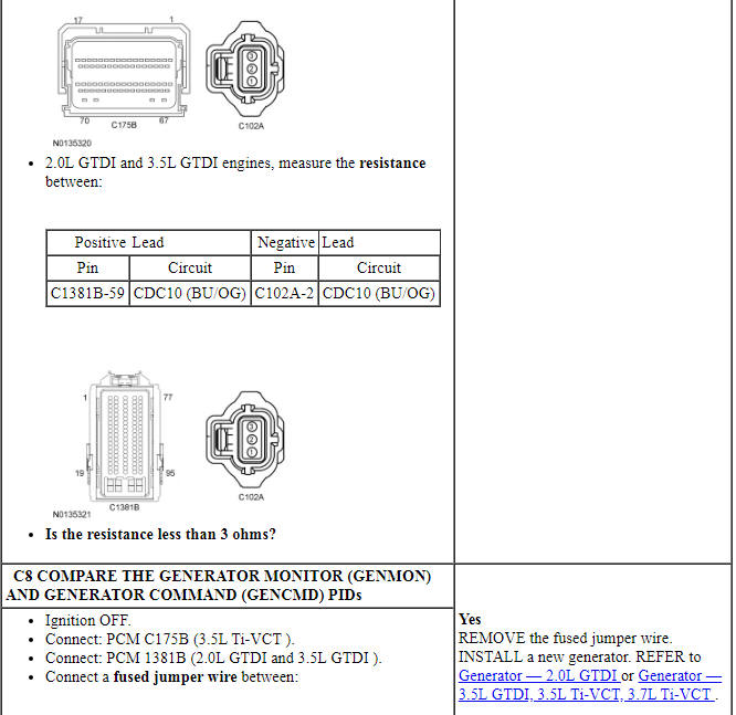
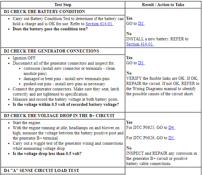
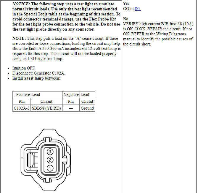
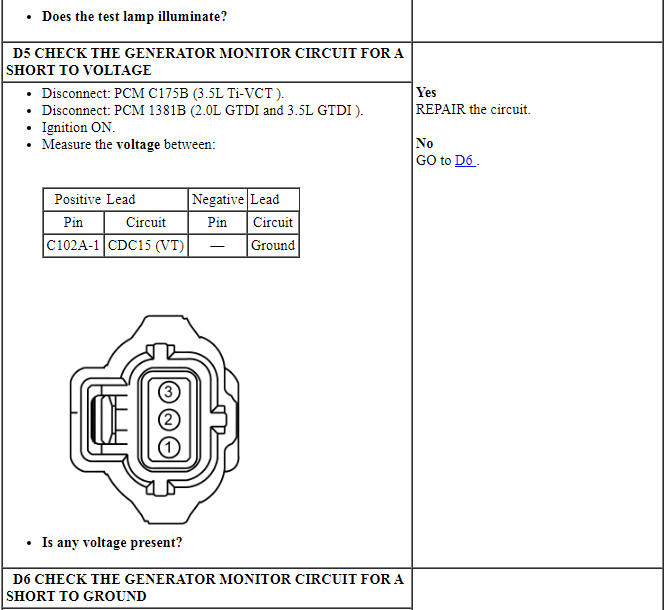
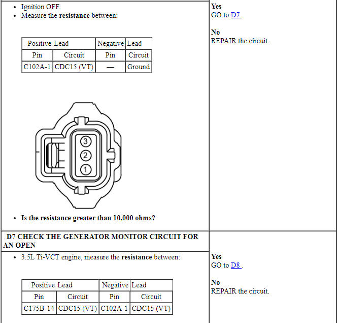
Pinpoint Test D: DTC P0625 or P0626
Diagnostic Overview
Diagnostics in this manual assume a certain skill level and knowledge of Ford-specific diagnostic practices. Refer to Diagnostic Methods in Section 100-00 for more information.
Refer to Wiring Diagrams Cell 12, Charging System for schematic and connector information.
Normal Operation and Fault Conditions
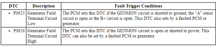
The PCM monitors the generator output via the generator monitor (GENMON) circuit (generator field terminal circuit). If the PCM cannot read the GENMON circuit due to an open or short to ground, when the engine speed is greater than 2,000 rpm, the generator defaults to a steady voltage of 13.5 volts and the PCM sends a request to the IPC to illuminate the charging system warning indicator. A GENMON duty cycle of 3% or less indicates a short to ground fault is present and results in DTC P0625 setting in the PCM. A GENMON duty cycle of 98% or more indicates an open or short to voltage fault is present and results in DTC P0626 setting in the PCM.
Visual Inspection and Diagnostic Pre-checks
Before diagnosing or repairing the charging system inspect the following items:
- Fusible links
- Abnormal ignition-off current drain(s)
- Battery
- Wiring, terminals or connectors
- High current BJB for loose or corroded connections
- Radial arm adapter (if equipped)
DTC Fault Trigger Conditions
-
This pinpoint test is intended to diagnose the following:
- Fuse
- Wiring, terminals or connectors
- Engine, generator and battery grounds
- Battery
- Generator
- PCM
- Radial arm adapter (if equipped)
PINPOINT TEST D: DTC P0625 or P0626
NOTE: Make sure battery voltage is greater than 12.2 volts prior to and during this pinpoint test.
NOTE: Do not have a battery charger attached during vehicle testing.
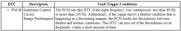
Pinpoint Test E: DTC P065B
Diagnostic Overview
Diagnostics in this manual assume a certain skill level and knowledge of Ford-specific diagnostic practices. Refer to Diagnostic Methods in Section 100-00 for more information.
Refer to Wiring Diagrams Cell 12, Charging System for schematic and connector information.
Normal Operation and Fault Conditions
With the engine running, the PCM monitors and expects to receive a valid generator monitor (GENMON) signal with a duty cycle greater than 5% and less than 98%. The PCM also monitors the state of the generator command (GENCMD) signal line to make sure it is not stuck high or stuck low. A DTC sets if the GENMON or GENCMD signal fluctuates between out-of-valid range, stuck high, stuck low, or some combination and normal. When the engine speed is greater than 2,000 rpm, the generator defaults to a steady voltage of 13.5 volts and the PCM sends a request to the IPC to illuminate the charging system warning indicator lamp.
Visual Inspection and Diagnostic Pre-checks
Before diagnosing or repairing the charging system inspect the following items:
- Fusible links
- Wiring, terminals or connectors
- High current BJB for loose or corroded connections
- Radial arm adapter (if equipped)
DTC Fault Trigger Conditions
-
This pinpoint test is intended to diagnose the following:
- Wiring, terminals or connectors
- Radial arm adapter (if equipped)
- Generator
- PCM
PINPOINT TEST E: DTC P065B
NOTE: Make sure battery voltage is greater than 12.2 volts prior to carrying out this pinpoint test.
NOTE: Do not have a battery charger attached during vehicle testing.
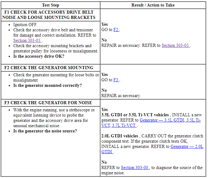
Pinpoint Test F: The Generator is Noisy
Diagnostic Overview
Diagnostics in this manual assume a certain skill level and knowledge of Ford-specific diagnostic practices. Refer to Diagnostic Methods in Section 100-00 for more information.
Refer to Wiring Diagrams Cell 12, Charging System for schematic and connector information.
Normal Operation and Fault Conditions
The generator is belt-driven by the engine accessory drive system. There are several sources of generator noise which include bearing noise, electrical fault noise, generator or belt pulley misalignment. A generator with certain types of diode or stator failures may also produce an audible noise.
Visual Inspection and Diagnostic Pre-checks
Before diagnosing or repairing the charging system inspect the following items:
- Fusible links
- Wiring, terminals or connectors
- High current BJB for loose or corroded connections
- Radial arm adapter (if equipped)
-
This pinpoint test is intended to diagnose the following:
- FEAD belt
- Loose bolts/brackets
- Generator/pulleys
PINPOINT TEST F: THE GENERATOR IS NOISY
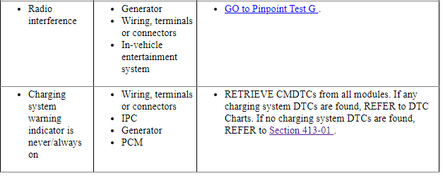
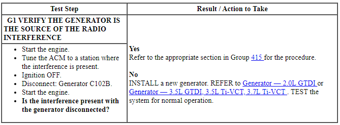
Pinpoint Test G: Radio Interference
Diagnostic Overview
Diagnostics in this manual assume a certain skill level and knowledge of Ford-specific diagnostic practices. Refer to Diagnostic Methods in Section 100-00 for more information.
Refer to Wiring Diagrams Cell 12, Charging System for schematic and connector information.
Normal Operation and Fault Conditions
The generator radio suppression equipment reduces interference transmitted through the speakers by the vehicle electrical system.
Visual Inspection and Diagnostic Pre-checks
Before diagnosing or repairing the charging system inspect the following items:
- Generator
- In-vehicle entertainment system
- Wiring, terminals or connectors
-
This pinpoint test is intended to diagnose the following:
- Generator
- Wiring, terminals or connectors
- In-vehicle entertainment system
PINPOINT TEST G: RADIO INTERFERENCE
NOTE: If the OEM ACM has been replaced with an aftermarket unit, the vehicle may not pass this test. Return the vehicle to OEM condition before following this pinpoint test.
NOTE: If the engine is operated at greater than 2,000 rpm momentarily, the generator self-excites. Make sure when the generator is disconnected the engine rpm stays below 2,000 rpm. If it exceeds 2,000 rpm, turn the ignition to the OFF position and start the test over again.
NOTE: Inspect for any aftermarket accessories that have been added to the vehicle. Check the wiring for these accessories and be sure they have not been attached to the generator circuits and are positioned away from the generator wiring.
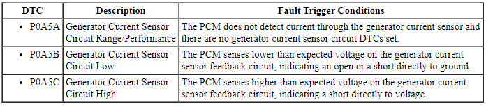
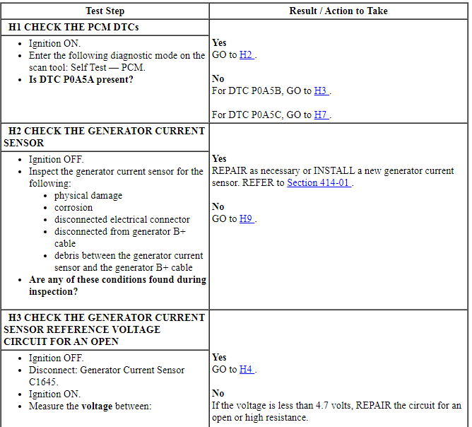
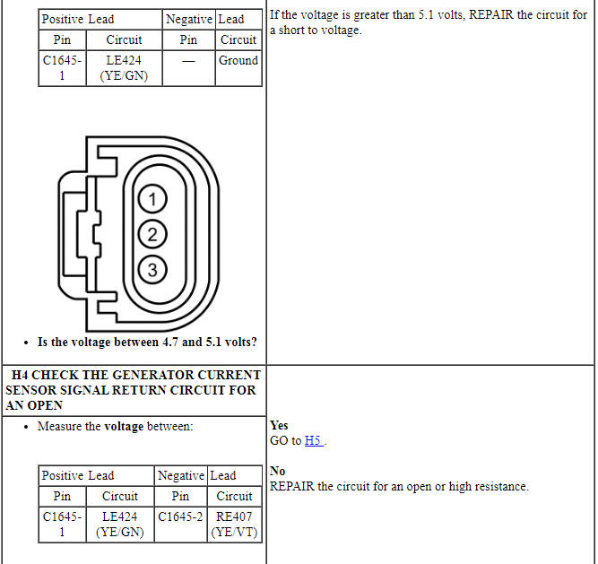
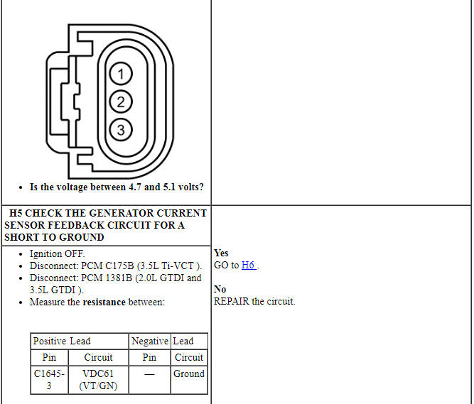
Pinpoint Test H: DTC P0A5A, P0A5B, P0A5C
Diagnostic Overview
Diagnostics in this manual assume a certain skill level and knowledge of Ford-specific diagnostic practices. Refer to Diagnostic Methods in Section 100-00 for more information.
Refer to Wiring Diagrams Cell 13, Power Distribution/BCM for schematic and connector information.
Normal Operation and Fault Conditions
The generator current sensor is a Hall-effect sensor attached to the generator B+ cable. It is supplied a 5 volt reference and ground from the PCM. The PCM reads the generator current sensor feedback voltage to determine how much current is flowing through the generator B+ cable.
Visual Inspection and Diagnostic Pre-checks
Before diagnosing or repairing the charging system inspect the following items:
- Generator current sensor
- Wiring, terminals or connectors
DTC Fault Trigger Conditions
-
This pinpoint test is intended to diagnose the following:
- Wiring, terminals or connectors
- Battery current sensor
- PCM
PINPOINT TEST H: DTC P0A5A, P0A5B, P0A5C
Diagnostic Overview
Diagnostics in this manual assume a certain skill level and knowledge of Ford-specific diagnostic practices. Refer to Diagnostic Methods in Section 100-00 for more information.
Refer to Wiring Diagrams Cell 13, Power Distribution/BCM for schematic and connector information.
Normal Operation and Fault Conditions
The battery current sensor is a Hall-effect sensor attached to the battery ground cable. It is supplied a 5 volt reference and ground from the BCM. The BCM reads the battery current sensor feedback voltage to determine how much current is flowing through the battery ground cable.
Visual Inspection and Diagnostic Pre-checks
Before diagnosing or repairing the charging system inspect the following items:
- Battery current sensor
- Inspect the wiring, terminals or connectors
DTC Fault Trigger Conditions
-
This pinpoint test is intended to diagnose the following:
- Wiring, terminals or connectors
- Battery current sensor
- BCM
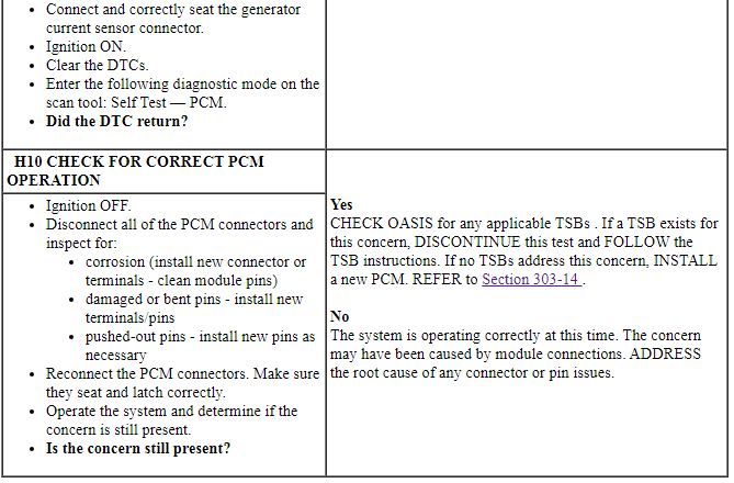
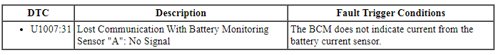
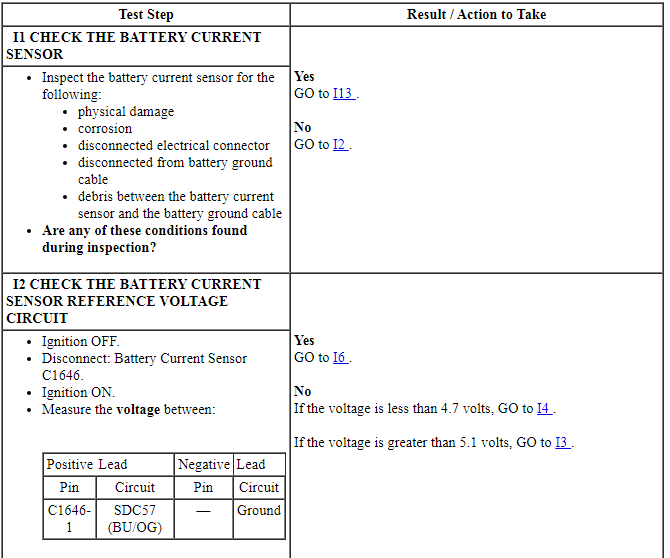
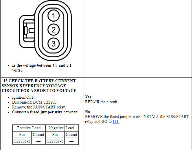
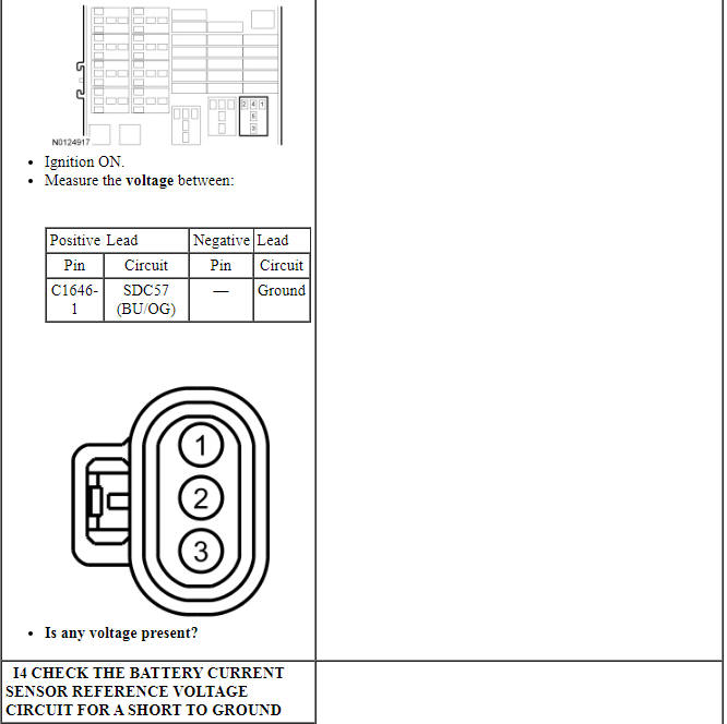
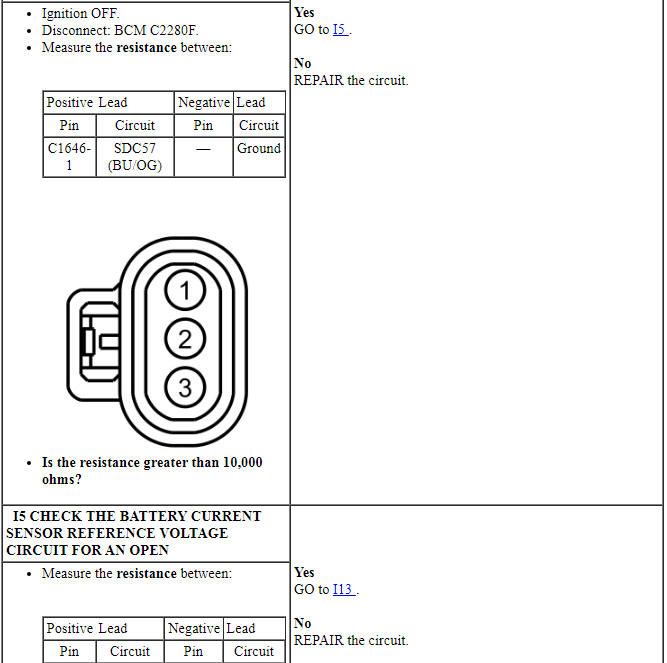
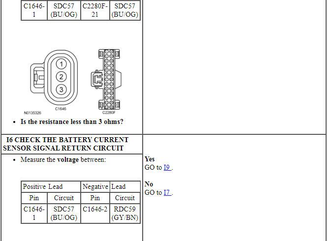
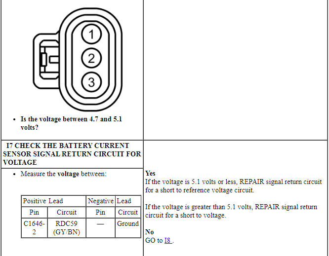
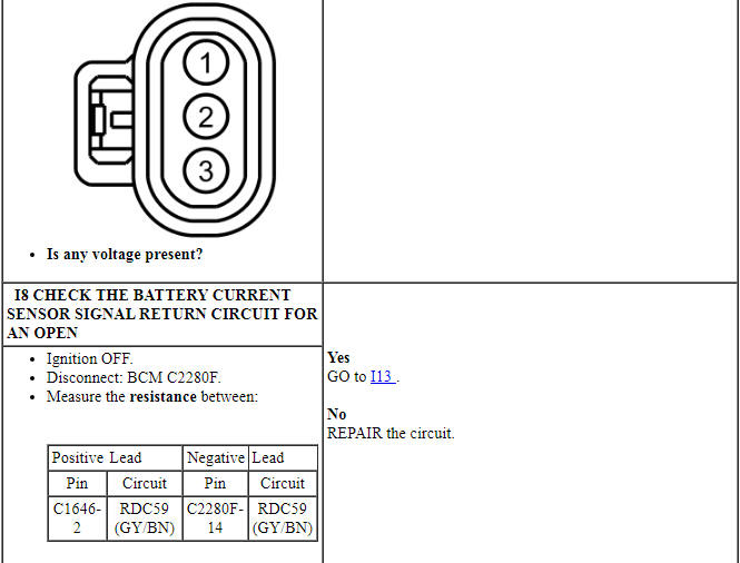
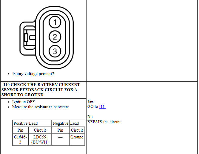
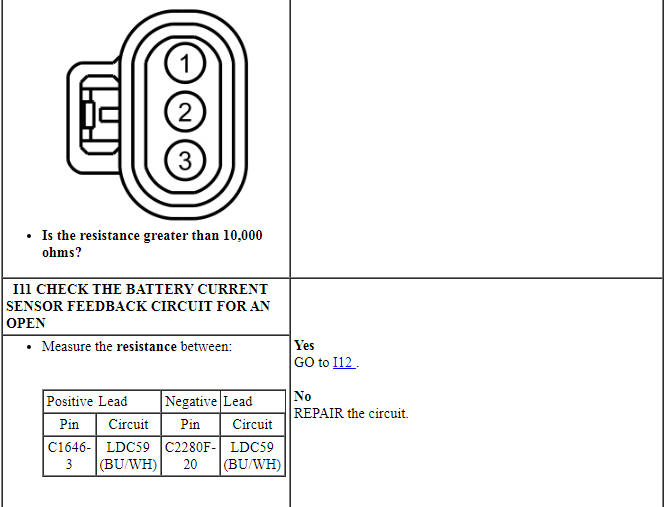
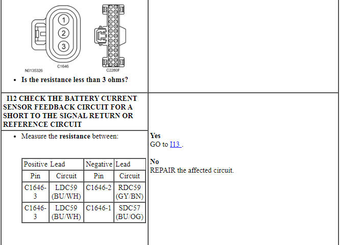
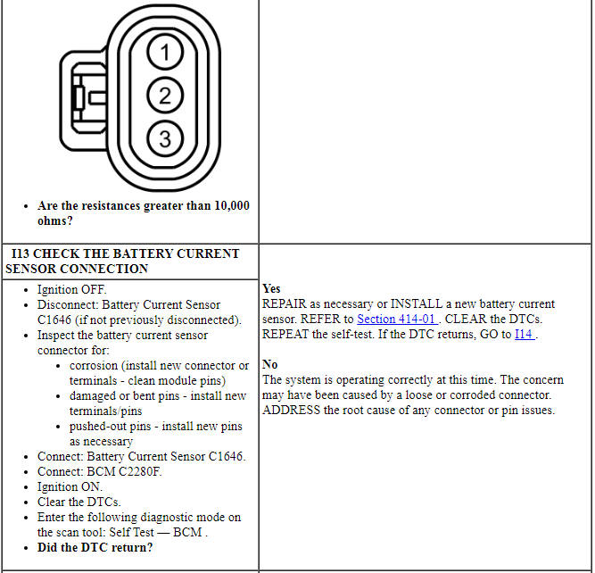
PINPOINT TEST I: U1007:31
Component Test
Generator Clutch
- NOTE: This procedure only applies to the 2.0L GTDI engine.
Remove the generator. Refer to Generator - 2.0L GTDI.
- Using a small screwdriver or similar tool, insert the tool through the rubber button on the center of the pulley cap and pry off the cap. Discard the cap. A new cap must be installed if the clutch is OK.
- Using a 17 mm hex tool bit and socket wrench, insert the 17 mm hex tool bit into the end of the clutch shaft.
- While holding the clutch pulley firmly by hand, turn the clutch shaft clockwise. The shaft should rotate smooth and freely. If the shaft rotation is rough or seized, install a new generator clutch. Refer to Generator Clutch.
- While holding the clutch pulley firmly by hand, turn the clutch shaft counterclockwise. There should be some resistance (a spring feel). If the shaft rotates freely, install a new generator clutch. Refer to Generator Clutch.
 Specifications, Description and Operation
SPECIFICATIONS
General Specifications
Torque Specifications
DESCRIPTION AND OPERATION
Charging System
Overview
The generator is driven by the accessory drive belt. When the engine is started, ...
 Removal and Installation
Generator - 2.0L GTDI
Removal
Disconnect the battery. For additional information, refer to Section
414-01.
Remove the upper Charge Air Cooler (CAC) pipe. For additional
informati ...
Other materials:
Satellite radio information
Satellite Radio Channels
Sirius broadcasts a variety of music, news, sports, weather, traffic and
entertainment satellite radio channels. For more information and a
complete list of Sirius satellite radio channels, visit www.siriusxm.com in
the United States, www.sirius.ca in Canada, or call Sir ...
Ford Extended Service Plan
PROTECT YOURSELF FROM THE RISING COST OF VEHICLE REPAIRS
WITH A FORD EXTENDED SERVICE PLAN.
SERVICE PLANS (U.S. only)
More than 32 Million Ford and Lincoln owners have discovered the
powerful protection Ford ESP. It is the only extended service plan
backed by Ford Motor Company, and provides pe ...
Removal and Installation
Headlamp Assembly
Removal
Remove the front bumper cover. Refer to Section 501-19.
Remove the headlamp assembly upper bolt.
To install, tighten to 3.2 Nm (28 lb-in).
Remove the headlamp assembly front bolt.
To install, tighten to 3.2 Nm (28 lb-in).
Remove the headlamp ...
