SPECIFICATIONS
Material
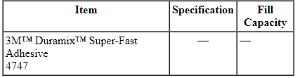
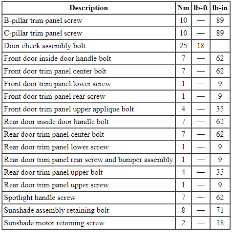
Torque Specifications
DIAGNOSIS AND TESTING
Sunshade
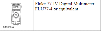
Special Tool(s)
Principles of Operation
Power Sunshade
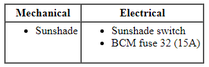
The power sunshade system consists of the following:
- Sunshade switch
- Sunshade module
- Sunshade motor
- Sunshade assembly
Pressing the sunshade switch (a single position, momentary contact, located next to the selector lever) sends a ground signal to the sunshade module. The sunshade module performs an auto up/auto down operation, depending on the current position of the sunshade. An auto up or auto down operation can be interrupted at any time by pressing the sunshade switch again. Pressing the sunshade switch again will cause the sunshade module to reverse the direction of the sunshade.
If the sunshade module senses the motor current draw has gone beyond 2.5A (obstruction), the sunshade module will remove power to the motor and the sunshade will stop.
When the selector lever is placed into the REVERSE position, the sunshade module receives a voltage signal from the backup lamp relay and the sunshade is lowered.
Inspection and Verification
- Verify the customer concern.
- Visually inspect for obvious signs of mechanical and electrical damage.
Visual Inspection Chart
- If an obvious cause for an observed or reported concern is found, correct the cause (if possible) before proceeding to the next step.
- If the cause is not visually evident, verify the symptom and GO to Symptom Chart.
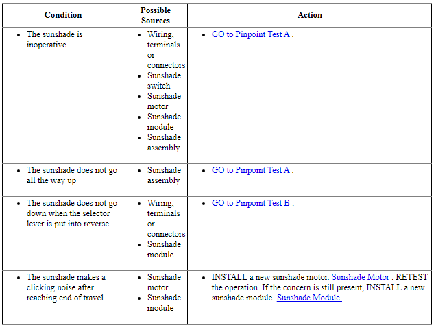
Symptom Chart
NOTE: Refer to Description and Operation, Intelligent Access with Push Button Start in Section 419-01A to review the procedures for achieving the various ignition states (ignition OFF, ignition in ACCESSORY, ignition ON, ignition START) on vehicles with this feature.
Pinpoint Test
Pinpoint Test A: The Sunshade is Inoperative
Refer to Wiring Diagrams Cell 104, Power Sunshade for schematic and connector information.
Normal Operation
The sunshade module receives voltage from the accessory delay relay. The sunshade switch provides a momentary ground signal to the sunshade module to raise or lower the sunshade.
-
This pinpoint test is intended to diagnose the following:
- Wiring, terminals or connectors
- Sunshade switch
- Sunshade motor
- Sunshade module
- Sunshade assembly
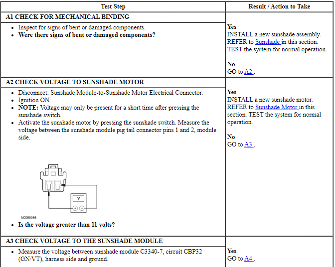
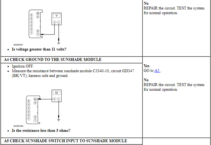
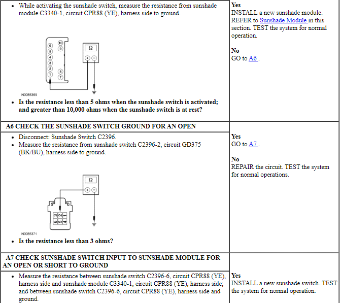
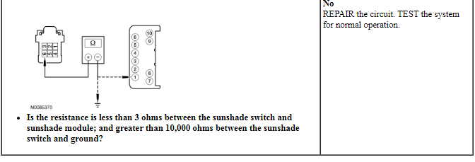
PINPOINT TEST A: THE SUNSHADE IS INOPERATIVE
Pinpoint Test B: The Sunshade Does Not Go Down When the Selector Lever is Put Into Reverse
Refer to Wiring Diagrams Cell 104, Power Sunshade for schematic and connector information.
Normal Operation
The sunshade module is spliced into the backup lamp relay circuit. When the backup lamps are activated, the sunshade module sees the voltage signal and lowers the sunshade, regardless of the current sunshade position.
-
This pinpoint test is intended to diagnose the following:
- Wiring, terminals or connectors
- Sunshade module
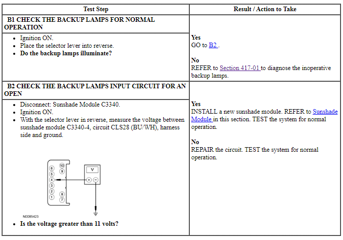
PINPOINT TEST B: THE SUNSHADE DOES NOT GO DOWN WHEN THE SELECTOR LEVER IS PUT INTO REVERSE
REMOVAL AND INSTALLATION
Scuff Plate Trim Panel - Front
- Pull the scuff plate trim panel upward to release the retaining clips.
- Remove the scuff plate trim panel.
- NOTICE: To avoid damage to the scuff plate trim panel, remove
any retaining clips from the body and attach them to the scuff plate trim
panel before installing.
To install, reverse the removal procedure.
Scuff Plate Trim Panel - Rear
Removal and Installation
- Remove the rear seat bolster. For additional information, refer to Section 501-10.
- Position the rear of the scuff plate trim panel away from the body mounting stud.
- Pull the front of the scuff plate trim panel upward to release the retaining clips.
- Pull the rear of the scuff plate trim panel upward to release the retaining clips.
- Remove the scuff plate trim panel.
- NOTICE: To avoid damage to the scuff plate trim panel, remove
any retaining clips from the body and attach them to the scuff plate trim
panel before installing.
To install, reverse the removal procedure.
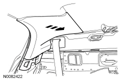
A-Pillar Trim Panel
Removal and Installation
- Position aside the door opening weatherstrip.
- NOTE: The A-pillar trim panel is equipped with a 2-stage
high-retention feature that is designed to prevent the A-pillar trim panel
from striking the occupant in the event of a side air curtain deployment.
Pull the A-pillar trim panel toward the center of the vehicle to release the first stage of the A-pillar trim panel 2-stage high-retention retaining clip.
- Squeeze the tabs of the 2-stage high-retention retaining clip to release the second stage of the 2-stage high-retention retaining clip while gently pulling the A-pillar trim panel inward toward the center of the vehicle.
- Pull the A-pillar trim panel upward and rearward to remove the A-pillar
trim from the instrument panel.
- If equipped, disconnect the speaker electrical connector.
Installation
- NOTICE: To avoid damage to the A-pillar trim panel, remove any
retaining clips from the body and attach them to the A-pillar trim panel
before installing.
Install a new A-pillar trim panel 2-stage high-retention retaining clip onto the A-pillar trim panel.
- Install the lower A-pillar trim panel tabs into the instrument panel.
- If equipped, connect the speaker electrical connector.
- Align the A-pillar trim panel retaining clips and the A-pillar trim panel locator pin to the A-pillar retaining clip holes and the A-pillar locator hole.
- Install the A-pillar trim panel onto the A-pillar.
- Make sure that the A-pillar trim panel retaining clips are seated correctly.
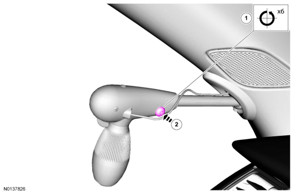
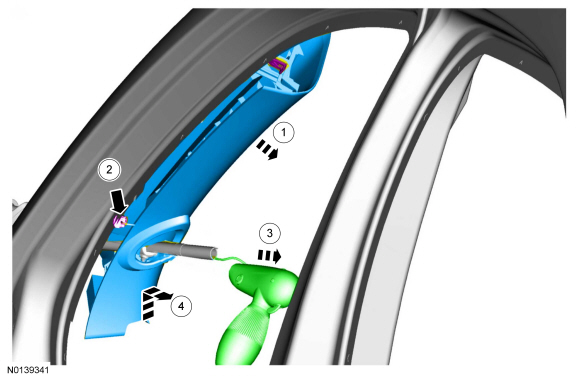
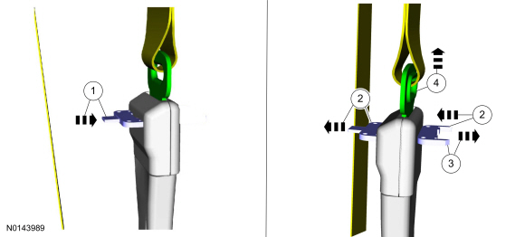
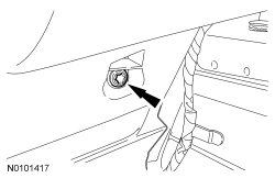
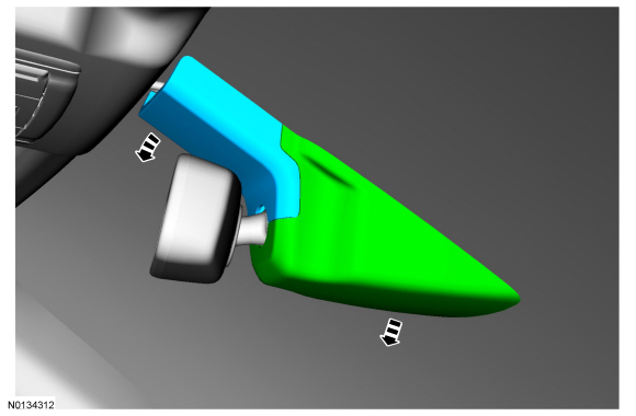
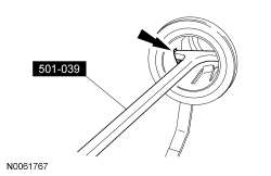
A-Pillar Trim Panel - Police Package
Removal and Installation
NOTE: Removal steps in this procedure may contain installation details.
-
- Turn the component Counterclockwise (CCW) through 6 complete turns.
- To install, tighten to 7 Nm (62 lb-in).
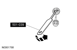
- Push the loosened screw to release the wedge nut.
- Turn the component Counterclockwise (CCW) through 6 complete turns.

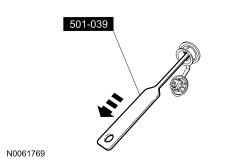
-
- To install, make sure the wedge nut aligns with the keyway on the spotlamp shaft.
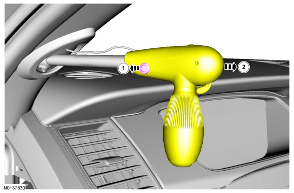
- To install, reverse the removal procedure.
B-Pillar Trim Panel
Removal and Installation
NOTE: Removal steps in this procedure may contain installation details.
Upper and lower trim panels
- Remove the front and rear door scuff plate trim panels. Refer to Scuff Plate Trim Panel - Front and Scuff Plate Trim Panel - Rear.
- NOTE: The service tools to disconnect the mini-buckle are
packaged with new safety belt assembly (54611B09/54611B08) and new safety
belt and anchor pretensioner (54601E45/54601E44) service kits.
NOTE: This step is only necessary when installing a new component.
- -
- NOTE: Allow insertion of the second tool to push the first tool from the mini-buckle.
- -
- NOTE: During installation, if the safety belt tongue cannot be inserted into the safety belt anchor and pretensioner, reset the latch inside the safety belt anchor and pretensioner using the service tool.
- NOTE: During installation, make sure the lower B-pillar trim panel is seated in the groove on the anchor pretensioner bellow's boot.
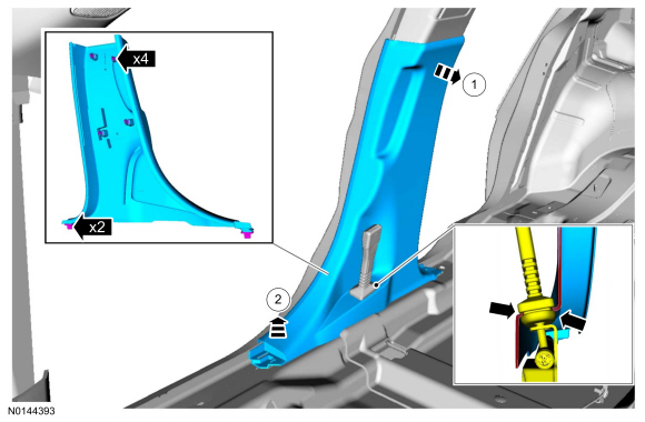
Upper trim panels
-
- To install, tighten to 10 Nm (89 lb-in).
Upper and lower trim panels
- NOTICE: To avoid damage to the B-pillar trim panels, remove
any retaining clips from the body and attach them to the B-pillar trim panel
before installing.
To install, reverse the removal procedure.
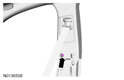
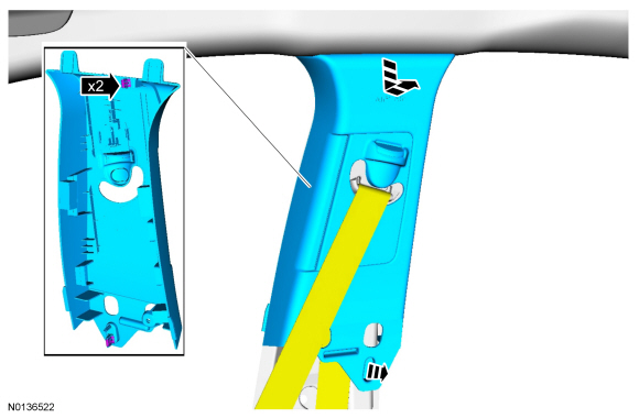
C-Pillar Trim Panel
Removal and Installation
- Remove the rear seat bolster. For additional information, refer to Section 501-10.
- NOTE: The seatback has been removed for clarity. The screw is
accessible with the seatback in place.
Remove the C-pillar trim panel screw.
- To install, tighten to 10 Nm (89 lb-in).
- NOTE: The seatback has been removed for clarity.
Remove the C-pillar trim panel.
- Pull the C-pillar toward the center of the vehicle.
- NOTICE: To avoid damage to the C-pillar trim panel, remove any
retaining clips from the body and attach them to the C-pillar trim panel
before installing.
To install, reverse the removal procedure.
Door Trim Panel - Front
NOTE: LH shown, RH similar.
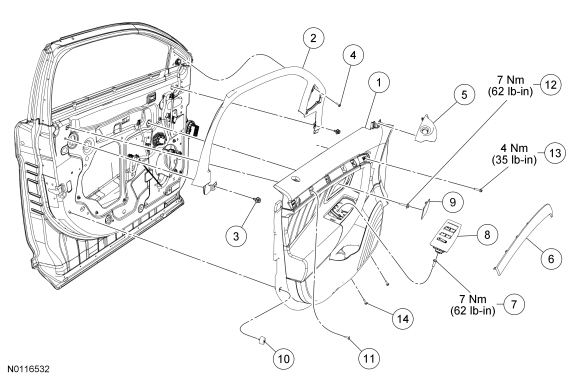
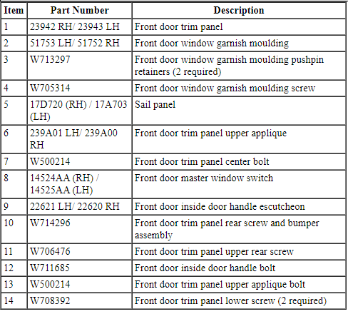
Removal and Installation
- Remove the sail panel.
- If equipped, disconnect the electrical connector.
- Remove the front door inside door handle escutcheon.
- Remove the front door inside door handle bolt.
- To install, tighten to 7 Nm (62 lb-in).
- Remove the front door master window switch and disconnect the electrical connector.
- Using a suitable trim tool, remove the front door trim panel upper applique.
- Remove the front door trim panel upper applique bolt.
- To install, tighten to 4 Nm (35 lb-in).
- Remove the front door trim panel upper rear screw.
- Remove the 2 front door trim panel lower screws.
- To install, tighten to 1 Nm (9 lb-in).
- Remove the front door trim panel rear screw and bumper assembly.
- To install, tighten to 1 Nm (9 lb-in).
- Remove the front door trim panel center bolt.
- To install, tighten to 7 Nm (62 lb-in).
- Remove the front door trim panel.
- Using a pushpin removal tool, pull the front door trim panel outward to release the retaining pushpins.
- Disconnect the inside door handle cable.
- Disconnect the electrical connectors.
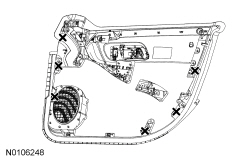
- NOTICE: To avoid damage to the front door trim panel, remove
any retaining clips from the front door and attach them to the front door
trim panel before installing.
To install, reverse the removal procedure.
Door Trim Panel - Rear
NOTE: Police package door trim panel similar to that shown.
NOTE: LH shown, RH similar.
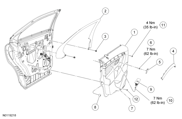
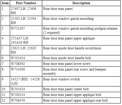
Removal and Installation
- Remove the rear door inside handle assembly escutcheon.
- Remove the rear door inside door handle bolt.
- To install, tighten to 7 Nm (62 lb-in).
- Using a suitable trim tool, pry upward to remove the rear door window switch.
- Remove the rear door trim panel center screw.
- To install, tighten to 7 Nm (62 lb-in).
- Using a suitable trim tool, remove the rear door trim panel upper applique.
- Remove the rear door trim panel upper applique bolt.
- To install, tighten to 4 Nm (35 lb-in).
- Remove the rear door trim panel lower screw.
- To install, tighten to 1 Nm (9 lb-in).
- Remove the rear door trim panel rear screw and bumper assembly.
- To install, tighten to 1 Nm (9 lb-in).
- Remove the rear door trim panel upper applique rear bolt.
- To install, tighten to 1 Nm (9 lb-in).
- Remove the rear door trim panel.
- Using a pushpin removal tool, pull the rear door trim panel outward to release the retaining pushpins.
- Disconnect the rear door handle assembly cable.
- Disconnect the electrical connectors.
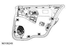
- NOTICE: To avoid damage to the door trim panel, remove any
retaining clips from the door and attach them to the door trim panel before
installing.
To install, reverse the removal procedure.
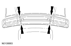
Parcel Shelf
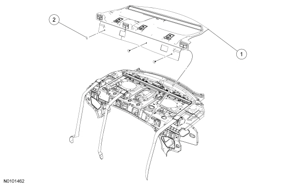
Removal and Installation
- Remove the LH and RH C-pillar trim panel. For additional information, refer to C-Pillar Trim Panel in this section.
- Position the rear seat back rest to the flat position.
- Remove the 3 parcel shelf pin-type retainers.
- Slide the rear safety belts through the parcel shelf slots until the safety belts are positioned under the parcel shelf.
- NOTE: During installation, if equipped with a sunshade, make sure
that the foam blocks on the parcel shelf are engaged on the sunshade tabs.
RH side shown LH side similar.
Remove the parcel shelf.
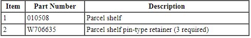
- Lift the front of the parcel shelf upward. Reach under the parcel shelf toward the back glass to separate the Velcro at the base of the parcel shelf.
- With slight pressure, pull the parcel shelf forward to remove.
- To install, reverse the removal procedure.
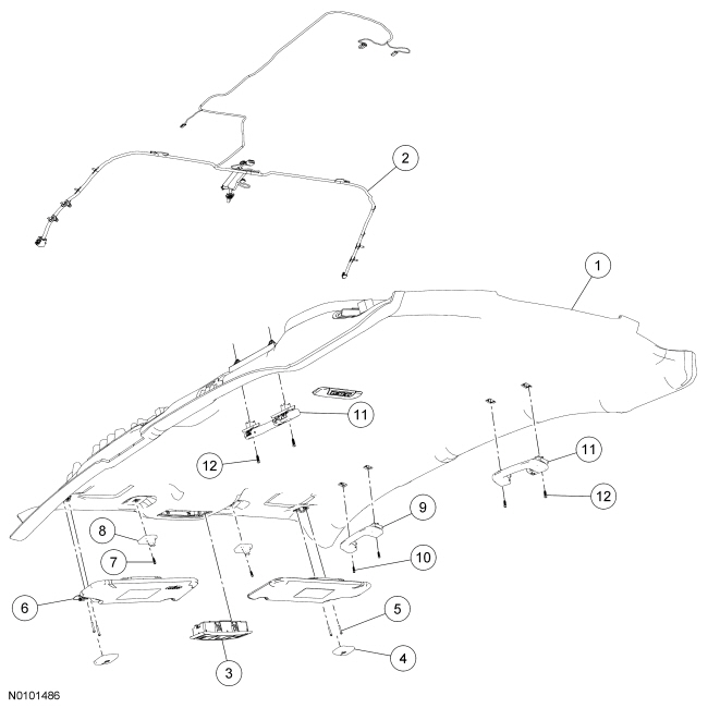
Headliner
Material
NOTE: Headliner equipped with moonroof.
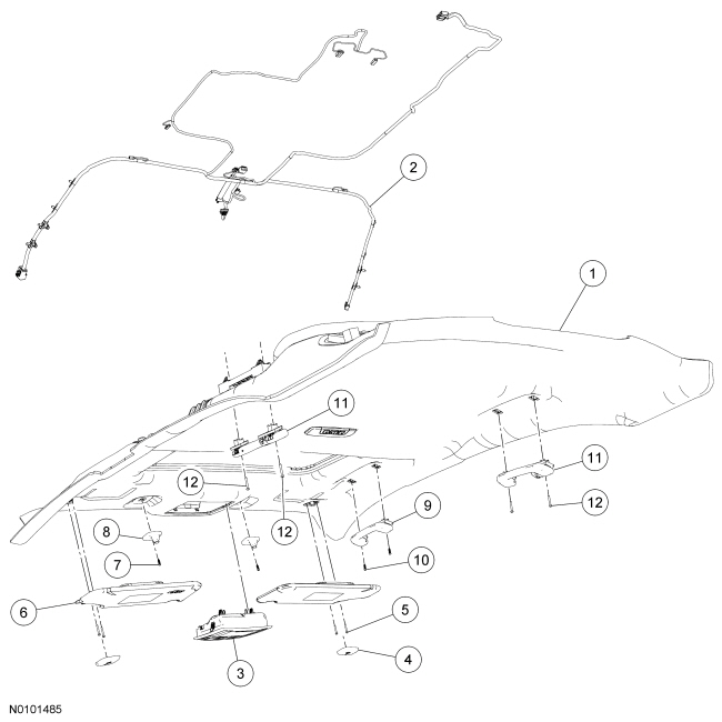
All vehicles
- Remove the LH and RH A-pillar trim panels. Refer to A-Pillar Trim Panel or A-Pillar Trim Panel - Police Package.
- Disconnect the electrical connector located on the lower LH and RH
A-pillar.
- Remove the wiring harness pin-type retainers.
- Remove the LH and RH sun visor.
- Remove the 2 sun visor retaining screws.
- If equipped, disconnect the electrical connectors.
- Remove the LH and RH sun visor clips.
- Remove the sun visor clip screws.
- If equipped.
- If equipped.
- Remove the front and rear assist handles.
- Open the assist handle retainer screw covers.
- Remove the assist handle retaining screws.
- If equipped, disconnect the ambient light electrical connector.
- Remove the left rear passenger side door check arm bolt.
- Remove 1 door check arm bolt from the body.
- To install, tighten to 25 Nm (18 lb-ft).
- Remove the LH and RH front seats. For additional information, refer to Section 501-10.
- Remove the front floor console. For additional information, refer to Section 501-12.
- Flatten the LH and RH carpet against floor and tape into position.
- Remove the LH and RH B-pillar trim panels. For additional information, refer to B-Pillar Trim Panel in this section.
- Completely remove the left rear door weatherstrip from opening.
- Remove the LH and RH C-pillar trim panels. For additional information, refer to C-Pillar Trim Panel in this section.
- Lower the door weatherstrips where they contact the headliner.
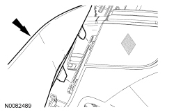
- Remove the 2 trim panel retaining clips from the rear of the headliner.
- Remove the 2 retaining clips using a pushpin puller.
Vehicles with roof opening panel
- Disconnect the roof opening panel electrical connector.
Vehicles without roof opening panel
- NOTICE: Do not cut below the front reinforcement support or
damage to the headliner will occur.
NOTE: The base headliner front reinforcement support must be cut to allow for flexing when removing through the door opening. Cut the support on the outer side of the reinforcement support rib.
NOTE: Replacement headliners have been pre-cut.
Lower the headliner and cut the front reinforcement support.- Using a cutoff wheel or suitable cutting tool, cut the support 8 mm (0.314 in) away from both the center support ribs, 20 mm (0.787 in) deep.
All vehicles
NOTE: The headliner is made of new material that will allow for specific folding and flexing during removal and installation.
- Remove the headliner.
- Rotate the headliner 90 degrees clockwise and remove the headliner through the left rear door opening.
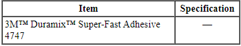
- NOTE: Obtain the 3M Duramix 4747 Super Fast Adhesive
commercially. The 3M Duramix 4747 Super Fast Adhesives a 2-part adhesive
in a 50 ml dual-tube applicator. Depending on the size of the headliner and
optional wire harness(es), the purchase of two to five 50 ml tubes is
suggested.
If installing a new headliner, transfer the wire harness in the following sequence:
- Using a suitable marking tool, mark the new headliner with the routing and exit points of the wire harness from the original headliner.
- Carefully remove the wire harness from the original headliner.
- NOTICE: Make sure not to damage the wire harness when
cutting the excess adhesive from the wire harness.
Cut and remove any excess adhesive from the wire harness.
- Position the wire harness onto the new headliner and check that the harness has enough length to be connected to the body/roof connectors. Apply tape to temporarily hold the wire harness in that position on the headliner.
- NOTE: The 3M Duramix 4747 Super Fast Adhesive will set in
20 seconds. Continually make sure that the wire harness is routed
correctly when applying the adhesive.
Apply the 3M Duramix 4747 Super Fast Adhesive in the same location as the factory installed adhesive along the full length of the wire harness-to-headliner to avoid any NVH concern(s).
- Transfer all necessary components.
- To install, reverse the removal procedure.
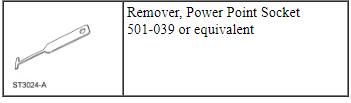
Power Point
Special Tool(s)
Removal
NOTE: Power point cover may differ depending on location.
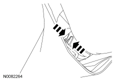
- Open the power point cover.
- Install the Power Point Socket Remover in one of the power point socket slots.
- Position the Power Point Socket Remover so that it engages in the adjacent slot.
- Using the Power Point Socket Remover, pull the power point socket out of the retainer.
- Disconnect the electrical connector.
Installation
- Connect the electrical connector.
- Slide the power point socket into the retainer.
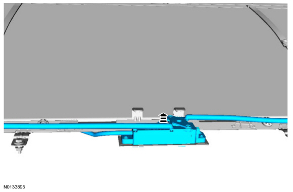
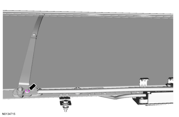
Sunshade
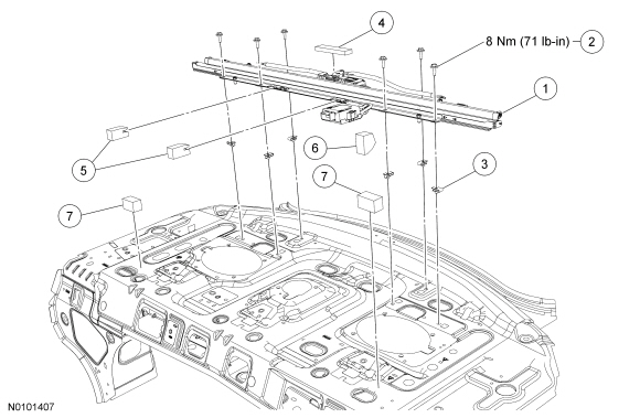
Removal and Installation
- Remove the parcel shelf. For additional information, refer to Parcel Shelf in this section.
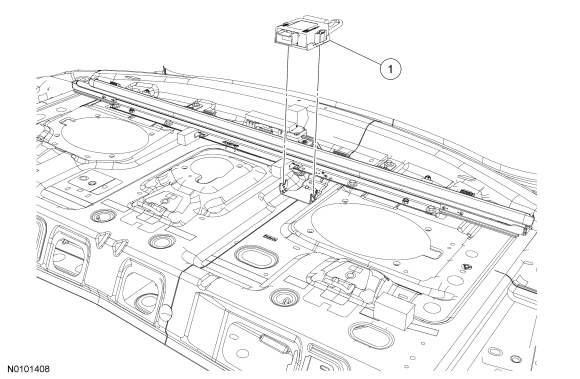
- Remove the sunshade assembly retainer bolts.
- To install, tighten to 8 Nm (71 lb-in).
- Disconnect the sunshade module electrical connector.
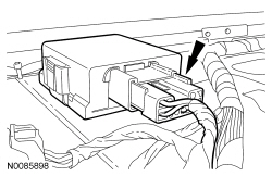
- Remove the sunshade assembly.
- To install, reverse the removal procedure.
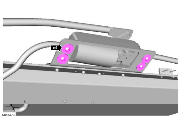
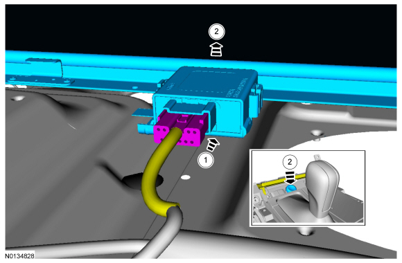
Sunshade Module
Removal and Installation
- Remove the rear seat. For additional information, refer to Section 501-10.
- Remove the parcel shelf. For additional information, refer to Parcel Shelf in this section.
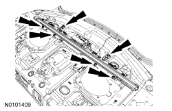
- Disconnect the sunshade module electrical connector.
- Press the tabs on the sunshade module to release the sunshade module from the sunshade module bracket.
- To install, reverse the removal procedure.
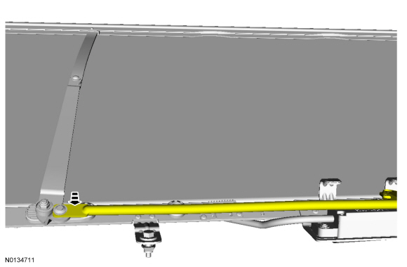
Sunshade Motor
Removal
- Remove the sunshade assembly. For additional information, refer to Sunshade in this section.
- On both sides. Discard the specified component.
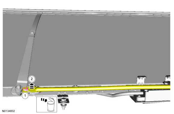

- Remove the cable tie.

Installation
NOTE: The new sunshade motor service part does not come in the normal rest position and must be positioned to the sunshade, connected and cycled in the vehicle to obtain the normal stowed position.
- NOTE: Do not install the push nuts on at this time.
On both sides.
- Install the sunshade motor screws finger tight.
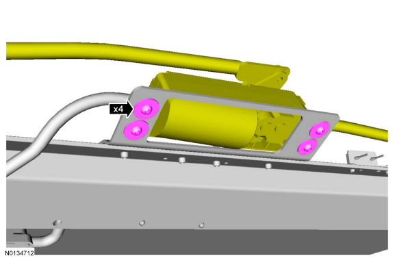
- Install new cable tie.
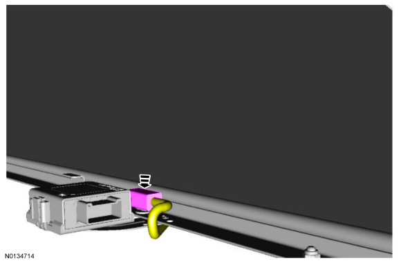
- NOTE: Taurus shown, MKS similar.
Set the sunshade assembly in the vehicle and cycle sunshade fully up.
- NOTE: Taurus shown, MKS similar.
Cycle sunshade fully down and remove the sunshade assembly from the vehicle.

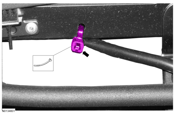
- Tighten to 2 Nm (18 lb-in).

- On both sides. Install new push nuts.
- Install the sunshade assembly. For additional information, refer to Sunshade in this section.
 Body Closures
SPECIFICATIONS
Torque Specifications
GENERAL PROCEDURES
Door Adjustment - Front
Loosen the front door hinge-to-front door bolts until the front door is
able to move slightly.
Align the front d ...
 Exterior Trim and Ornamentation
SPECIFICATIONS
Torque Specifications
REMOVAL AND INSTALLATION
Applique - Luggage Compartment Lid
Removal and Installation
NOTE: Removal steps in this procedure may contain installation
details. ...
Other materials:
Changing a fuse
Fuses
WARNING: Always replace a fuse with one that has the
specified amperage rating. Using a fuse with a higher amperage
rating can cause severe wire damage and could start a fire.
If electrical components in your
vehicle are not working, a fuse may
have blown. Blown fuses are
identified b ...
Multifunction Electronic Modules
SPECIFICATIONS
Torque Specifications
DESCRIPTION AND OPERATION
Module Controlled Functions
Component Location
Multifunction Electronic Modules
BCM
RFA module
Overview
The BCM controls the following:
Battery saver function
Brake shift interlock
Delayed accessory function
Dimm ...
Vehicle certification label
The National Highway Traffic Safety
Administration Regulations require
that a Safety Compliance Certification
Label be affixed to a vehicle and
prescribe where the Safety
Compliance Certification Label may
be located. The Safety Compliance
Certification Label shall be affixed to
either the ...
