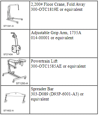
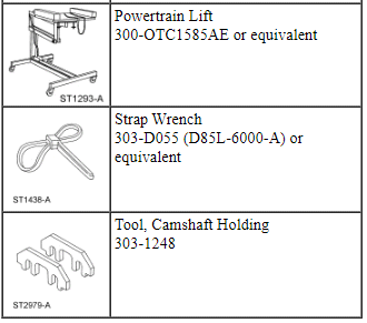
Engine
Special Tool(s)
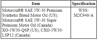
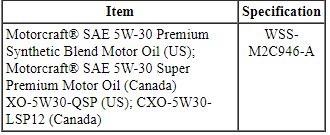
Material
NOTICE: Whenever turbocharger air intake system components are removed, always cover open ports to protect from debris. It is important that no foreign material enter the system. The turbocharger compressor vanes are susceptible to damage from even small particles. All components should be inspected and cleaned, if necessary, prior to installation or reassembly.
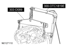
- Using the Floor Crane and Spreader Bar, align the transaxle to the engine.
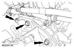
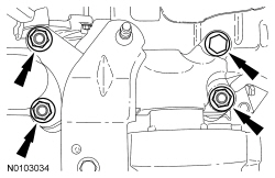
- Install the 3 engine-to-transaxle bolts.
- Tighten to 48 Nm (35 lb-ft).
- Install the LH engine-to-transaxle bolt.
- Tighten to 48 Nm (35 lb-ft).
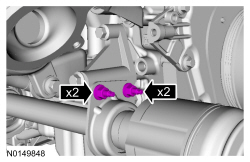
- Install the 2 LH bottom transaxle-to-engine bolts.
- Tighten to 48 Nm (35 lb-ft).
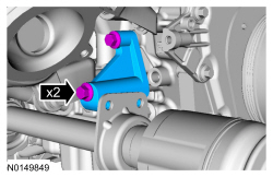
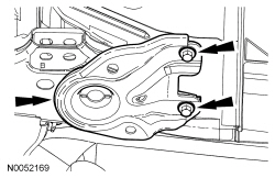
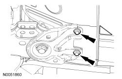
- Install the RH halfshaft support bracket and the 2 bolts.
- Tighten to 40 Nm (30 lb-ft).
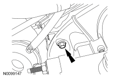
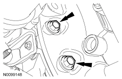
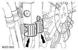
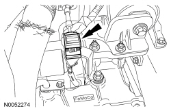
- Install the intermediate shaft bracket 2 studs and the 2 nuts.
- Tighten the studs to 10 Nm (89 lb-in).
- Tighten the nuts to 25 Nm (30 lb-ft).
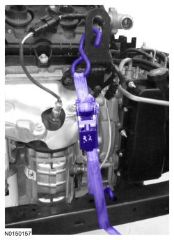
- NOTE: LH shown, RH similar.
Install the ratchet strap from the front subframe to the LH engine lift eye and from the rear of the subframe to the RH engine lift eye.
- Using the Floor Crane and Spreader Bar, install the powertrain and subframe as an assembly on the powertrain lift table.

- NOTE: LH shown, RH similar.
Remove the ratchet strap from the front subframe to the LH engine lift eye and from the rear of the subframe to the RH engine lift eye.

- Install the Adjustable Grip Arm.
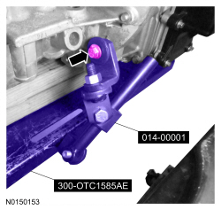
- Install a ratchet strap from the front of the subframe under the powertrain lift table to the rear of the subframe, to secure the subframe to the powertrain lift table.
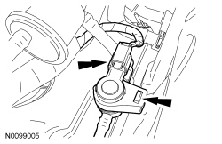
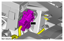
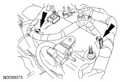
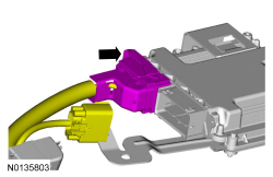
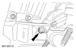
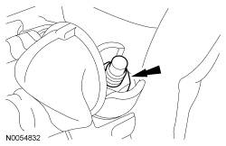
- Attach the transaxle control wire harness retainer to the transaxle stud bolt.
- Connect the transaxle control electrical connector.
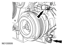
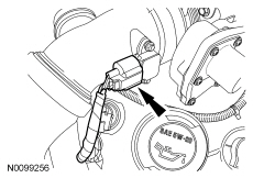
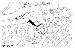
- Connect the generator electrical connector.

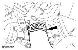
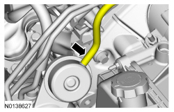
- Connect the generator B+ cable and install the nut.
- Tighten to 17 Nm (150 lb-in).

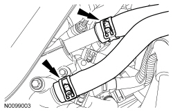
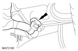
- Connect the A/C electrical connector and attach the wiring harness retainer.
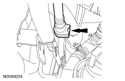
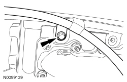
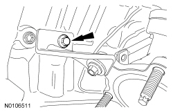
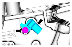
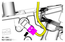
- Install the ground wire and the bolt to the RH cylinder head.
- Tighten to 10 Nm (89 lb-in).

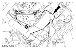
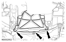
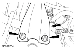
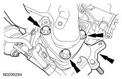
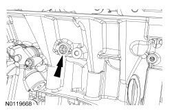
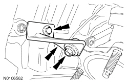
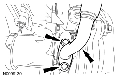
- Position the PTU support bracket in place and install the 3 bolts.
- Tighten the 2 bolts to 70 Nm (52 lb-ft).
- Tighten the bolt to 48 Nm (35 lb-ft).
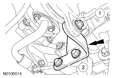
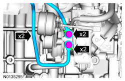
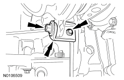
- Install the RH turbocharger lower bracket and the 3 bolts.
- Tighten the bolt to 19 Nm (168 lb-in).
- Tighten the 2 bolts to 48 Nm (35 lb-ft).
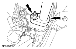
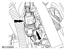
- Install the starter, the stud bolt and bolt.
- Tighten to 27 Nm (20 lb-ft).
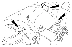
- Connect the wiring harness retainer to the starter motor stud bolt.

- Attach the starter wire terminals and install the 2 nuts.
- Tighten the B+ terminal nut to 12 Nm (106 lb-in).
- Tighten the S-terminal nut to 5 Nm (44 lb-in).
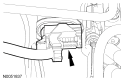
- Install the starter motor solenoid cover.
- Remove the Heavy Duty Floor Crane and Spreader Bar.

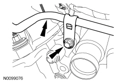
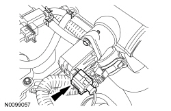
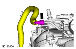
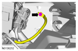
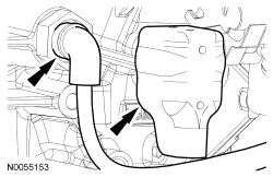
- Install the crankcase vent tube and connect the 2 quick connect couplings. For additional information, refer to Section 310-00.

- Remove the Engine Lift Eye from the LH cylinder head.
- Install the LH exhaust manifold heat shield and the 3 bolts.
- Tighten to 12 Nm (106 lb-in).
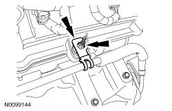
- Install the oil supply tube bracket on the LH valve cover stud bolt and
install the nut.
- Tighten to 8 Nm (71 lb-in).
- Attach the 4 wiring harness retainer to the valve cover stud bolt.
- Install the engine cover mounting stud to the LH valve cover stud bolt.
- Tighten to 6 Nm (53 lb-in).

- Remove the ratchet strap from the RH knuckle to subframe.
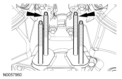
- NOTE: Make sure the struts go into the knuckles when raised.
Raise the subframe and powertrain assembly into the vehicle.
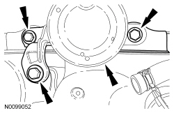
- Install the engine mount and the 3 bolts.
- Tighten to 90 Nm (66 lb-ft).
- Install the 4 engine mount nuts.
- Tighten to 63 Nm (46 lb-ft).
- Install the bolt and the 3 nuts for the transaxle support insulator
bracket-to-transaxle.
- Tighten the bolt to 80 Nm (59 lb-ft).
- Tighten the nuts to 63 Nm (46 lb-ft).

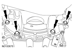
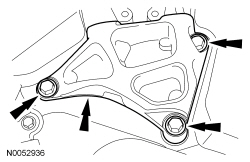
- NOTE: RH shown, LH similar.
Install the 2 front subframe bolts.
- Tighten to 200 Nm (148 lb-ft).
- NOTE: RH shown, LH similar.
Position the subframe brackets and install the 4 bolts finger-tight.
- NOTE: RH shown, LH similar.
Install the 2 rear subframe bolts.
- Tighten to 150 Nm (111 lb-ft).
- NOTE: RH shown, LH similar.
Tighten the 4 subframe bracket-to-body bolts to 55 Nm (41 lb-ft).

- Remove the ratchet strap from the front of the subframe to the rear of the subframe.
- Remove the Adjustable Grip Arm and the powertrain lift table.

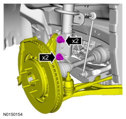
- NOTE: LH shown, RH similar.
Install the strut to the wheel knuckle and install the strut-to-wheel knuckle nuts and bolts.
- Tighten to 250 Nm (184 lb-ft).
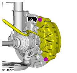
- NOTE: LH shown, RH similar.
Install the brake caliper and the guide pin bolts.
- 432 mm (17 in) brakes: Tighten to 72 Nm (53 lb-ft).
- 457 mm (18 in) brakes: Tighten to 75 Nm (55 lb-ft).
- NOTICE: Do not tighten the wheel hub nut with the vehicle on
the ground. The nut must be tightened to specification before the vehicle is
lowered onto the wheels. Wheel bearing damage will occur if the wheel
bearing is loaded with the weight of the vehicle applied.
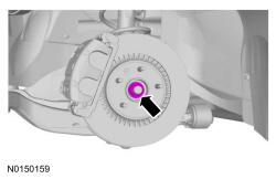
NOTE: LH shown, RH similar.
NOTE: Apply the brake to keep the halfshaft from rotating.
Using the previously removed wheel hub nut, seat the LH and RH halfshafts.- Tighten to 350 Nm (258 lb-ft).
- Remove and discard the wheel hub nuts.

- NOTICE: The wheel hub nut contains a one time locking chemical
that is activated by the heat created when it is tightened. Install and
tighten the new wheel hub nut to specification within 5 minutes of starting
it on the threads. Always install a new wheel hub nut after loosening or
when not tightened within the specified time or damage to the components can
occur.
NOTE: LH shown, RH similar.
NOTE: Apply the brake to keep the halfshaft from rotating.
Install a new wheel hub nuts.- Tighten to 350 Nm (258 lb-ft).
- NOTE: RH shown, LH similar.
Install new upper stabilizer bar link nuts.
- Tighten to 150 Nm (111 lb-ft).
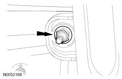
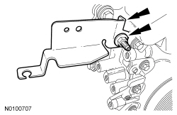
- NOTE: LH shown, RH similar.
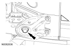
Install the wheel speed sensor and the bolt.
- Tighten to 15 Nm (133 lb-in).

- Install the 4 oil pan-to-transaxle bolts.
- Tighten to 48 Nm (35 lb-ft).
- Install 3 new torque converter bolts.
- Tighten to 55 Nm (41 lb-ft).
- Install the inspection cover and the 2 fasteners.
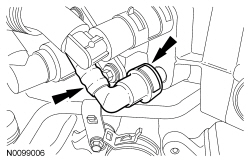
- Connect the transaxle cooler tubes and install the 2 secondary latches.

- If equipped, connect the 2 PTU coolant hoses.

- If equipped, install the oil cooler hose retainer to the subframe.

- If equipped, connect the oil cooler hoses.

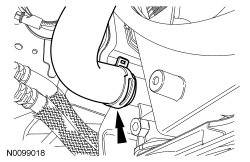
- Connect the lower radiator hose to the radiator.

- Attach the lower radiator hose retainer to the cooling fan and shroud.

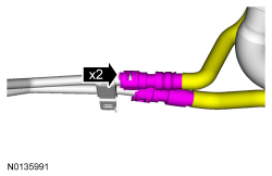
- NOTE: Align the index marks for the LH Charge Air Cooler (CAC)
tube.
Connect the lower LH CAC tube to the LH turbocharger.
- Tighten to 5 Nm (44 lb-in).

- Using a new O-ring seal and gasket seal, install the upper A/C tube to
the A/C compressor and install the nut.
- Tighten to 15 Nm (133 lb-in).

- Position the A/C tube bracket and install the bolt to the rear of the
A/C compressor.
- Tighten to 25 Nm (18 lb-ft).
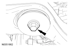
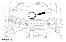
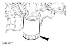
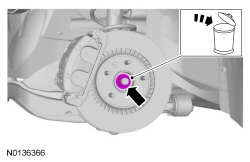
- Install a new engine oil filter.
- Tighten to 5 Nm (44 lb-in) and then rotate an additional 180 degrees.
- Line up the index marks on the rear driveshaft to the index marks on
the PTU flange made during removal and install the 4 new bolts.
- Tighten to 70 Nm (52 lb-ft).

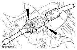
- NOTICE: Do not allow the intermediate shaft to
rotate while it is disconnected from the gear or damage to the clockspring
may occur. If there is evidence that the intermediate shaft has rotated, the
clockspring must be removed and recentered. For additional information,
refer to Section 501-20B.
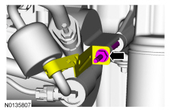
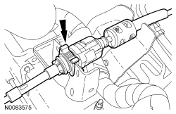
Install the steering intermediate shaft onto the steering gear and install a new bolt.
- Tighten to 20 Nm (177 lb-in).

- Install the RH and LH catalytic converters. For additional information, refer to Section 309-00.
- Install the 3 scrivets in the rubber shield.
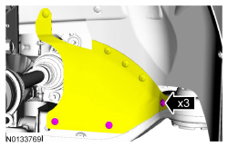
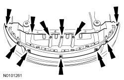
- Install the front splash shield, 3 pin-type retainers and the 7 bolts, when the cooling system or engine service is finished.
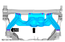
- If equipped, install the skid plate and the 10 bolts.
- Tighten to 70 Nm (52 lb-ft).
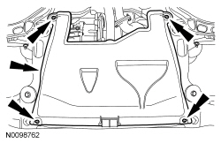
- If equipped, install the underbody shield and the 4 retainers.
- Install the front wheels and tires. For additional information, refer to Section 204-04.
- Connect the fuel supply tube. For additional information, refer to Section 310-00.

- Install the Evaporative Emission (EVAP) tube assembly and connect the quick connect coupling to the intake manifold. For additional information, refer to Section 310-00.

- Connect the EVAP valve electrical connector and attach to the intake manifold.
- Connect the EVAP tube quick connect coupling. For additional information, refer to Section 310-00.
- If equipped, attach the engine block heater harness to the radiator support wiring harness.
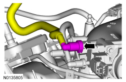
- Connect the upper radiator hose to the intake manifold coolant tube.
- Install the ground wire and bolt to the engine front cover.
- Tighten to 10 Nm (89 lb-in).

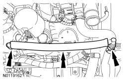
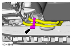
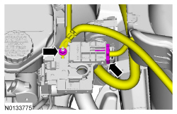
- Connect the 2 heater hoses to the intake manifold.
- NOTE: Align the index marks for the RH CAC tube.
Install the RH CAC tube and tighten the clamps.
- Tighten to 5 Nm (44 lb-in).

- Attach the wiring harness pin-type retainer and connect the transaxle control cable to the shift cable bracket.
- Connect the transaxle control cable to the control lever.

- Connect the quick connect coupling to the intake manifold. For additional information, refer to Section 310-00.

- Connect the battery power feed wire to the positive battery terminal and
install the nut.
- Connect the electrical connector.
- Tighten to 6 Nm (53 lb-in).

- Connect the engine wiring harness electrical connector.
- Position back the ground wire and install the bolt.
- Tighten to 6 Nm (53 lb-in).

- Install the battery tray. For additional information, refer to Section 414-01.
- NOTE: Align the index marks for the CAC outlet pipe.
Install the CAC outlet pipe and tighten the clamps.
- Tighten to 5 Nm (44 lb-in).

- Connect the Turbocharger Boost Pressure (TCBP)/Charge Air Cooler Temperature (CACT) sensor electrical connector.
- If equipped, install the noise generator. For additional information, refer to Intake Air System Components - Exploded View in Section 303-12.
- Install the engine Air Cleaner (ACL) and ACL outlet pipe. For additional information, refer to Section 303-12.
- Install the degas bottle. For additional information, refer to Section 303-03.
- Using a new O-ring seal and gasket seal, install the A/C tube and the
nut.
- Tighten to 15 Nm (133 lb-in).

- Using a new O-ring seal and gasket seal, connect the A/C tube and
install the nut.
- Tighten to 15 Nm (133 lb-in).
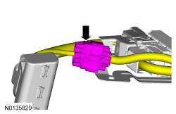
- Install the engine wiring harness retainer to the bulkhead.
- Slide the wiring harness in the bulkhead.
- Make sure the wiring harness retainer tab is below the bulkhead lip.
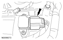
- Connect the PCM electrical connector.

- Connect the engine harness electrical connector.

- Install the strut tower brace and the 4 nuts.
- Tighten to 30 Nm (22 lb-ft).

- Attach the 2 brake booster vacuum hose retainers to the strut tower brace.
- Install the cowl panel grille. For additional information, refer to Section 501-02.
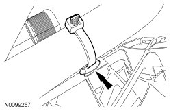
- Connect the LH Heated Oxygen Sensor (HO2S) electrical connector.
- Attach the HO2S connector retainer to the bracket.

- Fill the engine with clean engine oil.
- Fill and bleed the cooling system. For additional information, refer to Section 303-03.
- Recharge the A/C system. For additional information, refer to Section 412-00.
- Perform the Misfire Monitor Neutral Profile Correction procedure following the on-screen instructions.
Camshaft
Special Tool(s)
Material
Installation
WARNING: Do not smoke, carry lighted tobacco or have an open flame of any type when working on or near any fuel-related component. Highly flammable mixtures are always present and may be ignited. Failure to follow these instructions may result in serious personal injury.
NOTICE: Whenever turbocharger air intake system components are removed, always cover open ports to protect from debris. It is important that no foreign material enter the system. The turbocharger compressor vanes are susceptible to damage from even small particles. All components should be inspected and cleaned, if necessary, prior to installation or reassembly.
NOTICE: During engine repair procedures, cleanliness is extremely important. Any foreign material, including any material created while cleaning gasket surfaces that enters the oil passages, coolant passages or the oil pan, may cause engine failure.
All camshafts
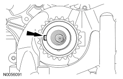
- NOTICE: The crankshaft must remain in the freewheeling
position (crankshaft dowel pin at 9 o'clock) until after the camshafts are
installed and the valve clearance is checked/adjusted. Do not turn the
crankshaft until instructed to do so. Failure to follow this process will
result in severe engine damage.
Rotate the crankshaft counterclockwise until the crankshaft dowel pin is in the 9 o'clock position.
LH camshafts
- NOTICE: The camshafts must remain in the neutral position
during installation or engine damage may occur.
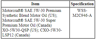
NOTE: Coat the camshafts with clean engine oil prior to installation.
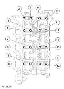
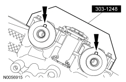
Position the camshafts onto the LH cylinder head in the neutral position as shown.
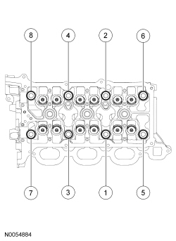
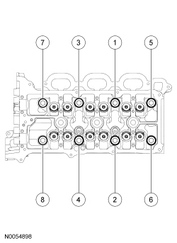
- NOTE: Cylinder head camshaft bearing caps are numbered to verify
that they are assembled in their original positions.
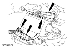
Install the 8 camshaft caps and the 16 bolts. Tighten the bolts in the sequence shown in the following stages:
- Stage 1: Tighten bolts 1, 2, 3 and 4 to 8 Nm (71 lb-in) then an additional 45 degrees.
- Stage 2: Tighten bolts 5 and 6 to 8 Nm (71 lb-in).
- Stage 3: Tighten bolts 7 and 8 to 8 Nm (71 lb-in) then an additional 45 degrees.
- Stage 4: Loosen bolts 5 and 6.
- Tighten bolts 5 and 6 to 8 Nm (71 lb-in) then an additional 45 degrees.
- Stage 5: Tighten bolts 9, 10, 11 and 12 to 8 Nm (71 lb-in) then an additional 45 degrees.
- Stage 6: Tighten bolts 13 and 14 to 8 Nm (71 lb-in).
- Stage 7: Tighten bolts 15 and 16 to 8 Nm (71 lb-in) then an additional 45 degrees.
- Stage 8: Loosen bolts 13 and 14.
- Tighten bolts 13 and 14 to 8 Nm (71 lb-in) then an additional 45 degrees.
RH camshafts
- NOTICE: The camshafts must remain in the neutral position
during installation or engine damage may occur.
NOTE: Coat the camshafts with clean engine oil prior to installation.
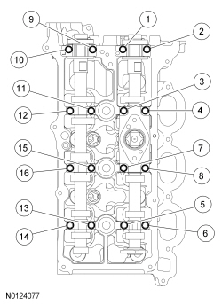
Position the camshafts onto the RH cylinder head in the neutral position as shown.
- NOTE: Cylinder head camshaft bearing caps are numbered to verify
that they are assembled in their original positions.
Install the 8 camshaft caps and the 16 bolts. Tighten the bolts in the sequence shown in the following stages:
- Stage 1: Tighten bolts 1, 2, 3 and 4 to 8 Nm (71 lb-in) then an additional 45 degrees.
- Stage 2: Tighten bolts 5 and 6 to 8 Nm (71 lb-in).
- Stage 3: Tighten bolts 7 and 8 to 8 Nm (71 lb-in) then an additional 45 degrees.
- Stage 4: Loosen bolts 5 and 6.
- Tighten bolts 5 and 6 to 8 Nm (71 lb-in) then an additional 45 degrees.
- Stage 5: Tighten bolts 9, 10, 11 and 12 to 8 Nm (71 lb-in) then an additional 45 degrees.
- Stage 6: Tighten bolts 13 and 14 to 8 Nm (71 lb-in).
- Stage 7: Tighten bolts 15 and 16 to 8 Nm (71 lb-in) then an additional 45 degrees.
- Stage 8: Loosen bolts 13 and 14.
- Tighten bolts 13 and 14 to 8 Nm (71 lb-in) then an additional 45 degrees.
All camshafts
- NOTICE: If any components are installed new, the engine valve
clearance must be checked/adjusted or engine damage may occur.
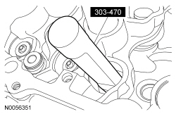
NOTE: Use a camshaft sprocket bolt to turn the camshafts.
Using a feeler gauge, confirm that the valve tappet clearances are within specification. If valve tappet clearances are not within specification, the clearance must be adjusted by installing new valve tappet(s) of the correct size. For additional information, refer to Valve Clearance Check in this section.
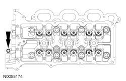
LH camshafts
- NOTE: Use a camshaft sprocket bolt to turn the camshafts.
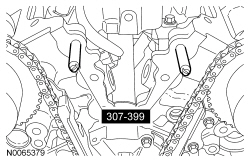
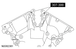
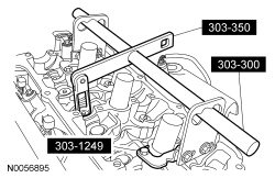
Rotate the LH camshafts to the Top Dead Center (TDC) position and install the Camshaft Holding Tool on the flats of the camshafts.
- Assemble the LH Variable Camshaft Timing (VCT) assembly, the LH exhaust
camshaft sprocket and the LH secondary timing chain.
- Align the colored links with the timing marks.
- Position the LH secondary timing assembly onto the camshafts.
- Install 2 new bolts and the original washer. Tighten in 4 stages.
- Stage 1: Tighten to 40 Nm (30 lb-ft).
- Stage 2: Loosen one full turn.
- Stage 3: Tighten to 10 Nm (89 lb-in).
- Stage 4: Tighten 90 degrees.

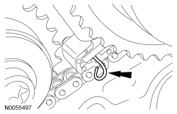
- Remove the lockpin from the LH secondary timing chain tensioner.
RH camshafts
- NOTE: Use a camshaft sprocket bolt to turn the camshafts.
Rotate the RH camshafts to the TDC position and install the Camshaft Holding Tool on the flats of the camshafts.
- Assemble the RH VCT assembly, the RH exhaust camshaft sprocket and the
RH secondary timing chain.
- Align the colored links with the timing marks.
- Position the RH secondary timing assembly onto the camshafts.
- Install 2 new bolts and the original washer. Tighten in 4 stages.
- Stage 1: Tighten to 40 Nm (30 lb-ft).
- Stage 2: Loosen one full turn.
- Stage 3: Tighten to 10 Nm (89 lb-in).
- Stage 4: Tighten 90 degrees.
- Remove the lockpin from the RH secondary timing chain tensioner.
All camshafts
- Rotate the crankshaft clockwise 60 degrees to the TDC position (crankshaft dowel pin at 11 o'clock).
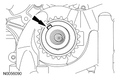
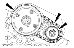
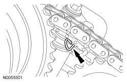
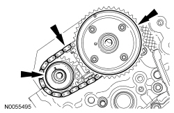
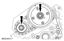
- NOTE: The crankshaft sprocket timing mark should be between the 2
colored links.
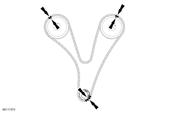
Install the primary timing chain with the colored links aligned with the timing marks on the VCT assemblies and the crankshaft sprocket.
- Install the lower LH primary timing chain guide and the 2 bolts.
- Tighten to 10 Nm (89 lb-in).
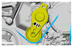
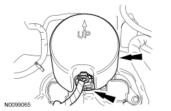
- Install the primary timing chain tensioner arm.
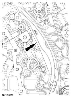
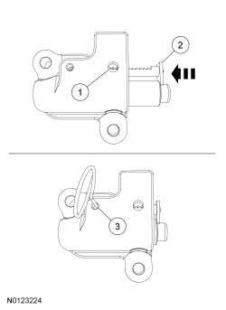
- Reset the primary timing chain tensioner.
- Release the ratchet detent.
- Using a soft-jawed vise, compress the ratchet plunger.
- Align the hole in the ratchet plunger with the hole in the tensioner housing and install a suitable lockpin.
- NOTE: It may be necessary to rotate the crankshaft slightly to
remove slack from the timing chain and install the tensioner.
Install the primary tensioner and the 2 bolts.
- Tighten to 10 Nm (89 lb-in).
- Remove the lockpin.
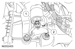
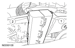
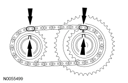
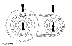
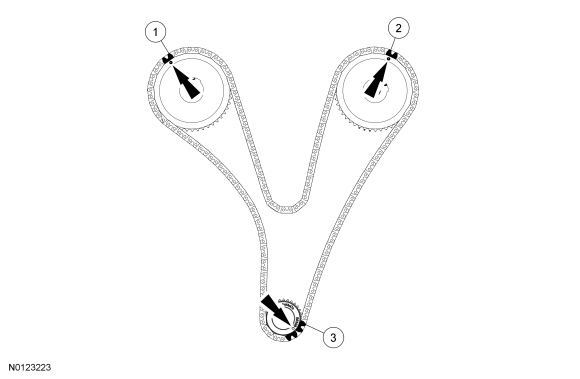
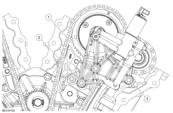
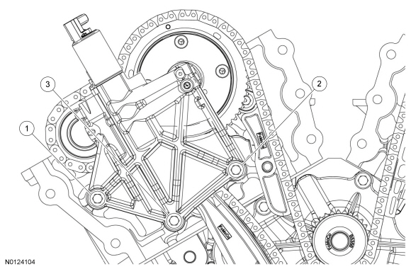
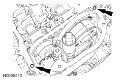
- As a post-check, verify correct alignment of all timing marks.
- There are 48 links between the RH intake VCT assembly colored link (1) and the LH intake VCT assembly colored link (2).
- There are 35 links between the LH intake VCT assembly colored link (2) and the 2 crankshaft sprocket colored links (3).
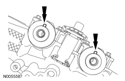
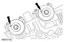
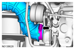
- Inspect the VCT housing seals for damage and replace as necessary.
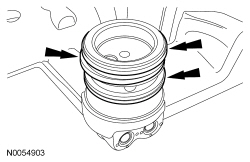
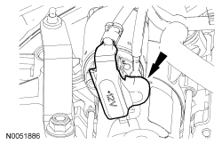
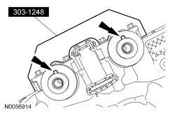
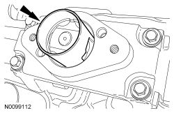
- NOTE: RH shown, LH similar.
NOTE: During removal, the O-ring seal may remain on the cylinder head. If so, remove the O-ring seal from the cylinder head, inspect the seal (replace as necessary) and install the O-ring seal on the VCT housing.
Inspect the VCT housing-to-cylinder head O-ring seals for damage and replace as necessary.
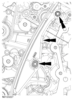
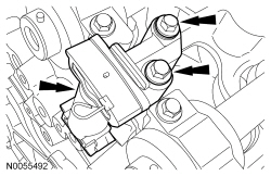
- NOTICE: Make sure the dowels on the Variable Camshaft Timing
(VCT) housing are fully engaged in the cylinder head prior to tightening the
bolts. Failure to follow this process will result in severe engine damage.
Install the LH VCT housing and the 3 bolts.
- Tighten in the sequence shown to 10 Nm (89 lb-in).
- NOTICE: Make sure the dowels on the Variable Camshaft Timing
(VCT) housing are fully engaged in the cylinder head prior to tightening the
bolts. Failure to follow this process will result in severe engine damage.
Install the RH VCT housing and the 3 bolts.
- Tighten in the sequence shown to 10 Nm (89 lb-in).
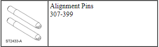
- Install the Alignment Pins.
- NOTICE: Failure to use Motorcraft High Performance Engine RTV
Silicone may cause the engine oil to foam excessively and result in serious
engine damage.
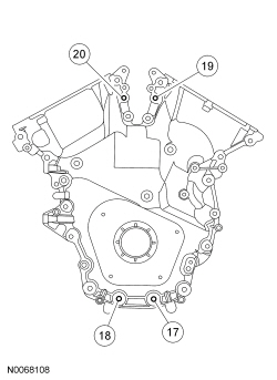
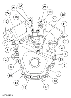
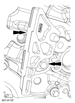
NOTE: The engine front cover and bolts 17, 18, 19 and 20 must be installed within 4 minutes of the initial sealant application. The remainder of the engine front cover bolts and the engine mount bracket bolts must be installed and tightened within 35 minutes of the initial sealant application. If the time limits are exceeded, the sealant must be removed, the sealing area cleaned and sealant reapplied. To clean the sealing area, use silicone gasket remover and metal surface prep. Failure to follow this procedure can cause future oil leakage.
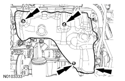
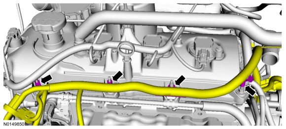
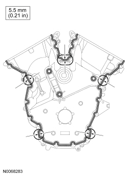
Apply a 3.0 mm (0.11 in) bead of Motorcraft High Performance Engine RTV Silicone to the engine front cover sealing surfaces including the 3 engine mount bracket bosses.- Apply a 5.5 mm (0.21 in) bead of Motorcraft High Performance Engine RTV Silicone to the oil pan-to-cylinder block joint and the cylinder head-to-cylinder block joint areas of the engine front cover in 5 places as indicated.
- NOTE: Make sure the 2 locating dowel pins are seated correctly in
the cylinder block.
Install the engine front cover and bolts 17, 18, 19 and 20.
- Tighten in sequence shown to 3 Nm (27 lb-in).
- Remove the Alignment Pins.
- NOTE: Do not tighten the bolts at this time.
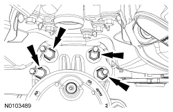
Install the engine mount bracket and the 3 bolts.
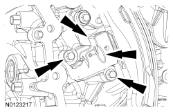
- Install the remaining engine front cover bolts. Tighten all of the
engine front cover bolts and engine mount bracket bolts in the sequence
shown in 2 stages:
- Stage 1: Tighten bolts 1 thru 22 to 10 Nm (89 lb-in) and bolts 23, 24 and 25 to 15 Nm (133 lb-in).
- Stage 2: Tighten bolts 1 thru 22 to 24 Nm (18 lb-ft) and bolts 23, 24 and 25 to 75 Nm (55 lb-ft).
- NOTICE: The thread sealer on the engine mount studs (including
new engine mount studs if applicable) must be cleaned off with a wire brush
and new Threadlock and Sealer applied prior to installing the engine mount
studs. Failure to follow this procedure may result in damage to the engine
mount studs or engine.
Install the engine mount studs in the following sequence.
- Clean the front cover engine mount stud holes with pressurized air to remove any foreign material.
- Clean all the thread sealer from the engine mount studs (old and new studs).
- Apply new Threadlock and Sealer to the engine mount stud threads.
- Install the 2 engine mount studs.
- Tighten to 20 Nm (177 lb-in).
- Install the Heated Oxygen Sensor (HO2S) connector bracket and stud bolt
to the engine front cover.
- Tighten to 10 Nm (89 lb-in).
- NOTE: Apply clean engine oil to the crankshaft front seal bore in
the engine front cover.
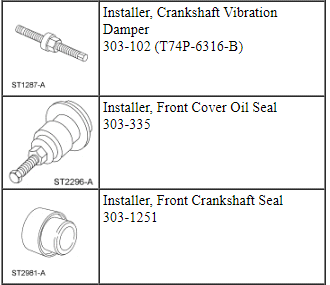
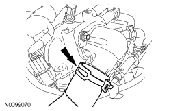
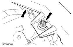
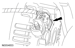
Using the Crankshaft Vibration Damper Installer and Front Crankshaft Seal Installer, install a new crankshaft front seal.
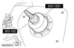
- NOTE: Lubricate the outside diameter sealing surfaces with clean
engine oil.
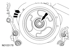
Using the Crankshaft Vibration Damper Installer and Front Cover Oil Seal Installer, install the crankshaft pulley.
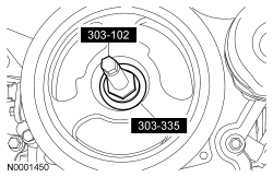
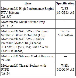
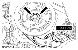
- Using the Strap Wrench, install the crankshaft pulley washer and new
bolt and tighten in 4 stages.
- Stage 1: Tighten to 120 Nm (89 lb-ft).
- Stage 2: Loosen one full turn.
- Stage 3: Tighten to 50 Nm (37 lb-ft).
- Stage 4: Tighten an additional 90 degrees.
- Install the accessory drive belt tensioner and the 3 bolts.
- Tighten to 11 Nm (97 lb-in).
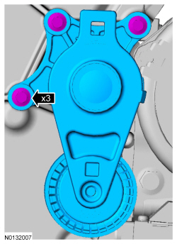
- Rotate the accessory drive belt tensioner clockwise and install the accessory drive belt.
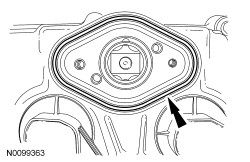
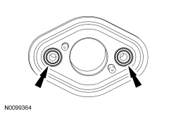
- NOTE: Installation of new seals is only required if damaged seals
were removed during disassembly of the engine.
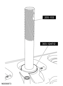
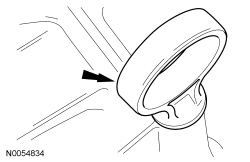
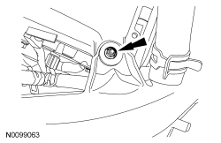
NOTE: Spark plug tube seal installation shown, VCT solenoid seal installation similar.
Using the VCT Spark Plug Tube Seal Installer and Handle, install new VCT solenoid and/or spark plug tube seals.
- NOTICE: Failure to use Motorcraft High Performance Engine RTV
Silicone may cause the engine oil to foam excessively and result in serious
engine damage.
NOTE: If the valve cover is not installed and the fasteners tightened within 4 minutes, the sealant must be removed and the sealing area cleaned. To clean the sealing area, use silicone gasket remover and metal surface prep. Failure to follow this procedure can cause future oil leakage.
Apply an 8 mm (0.31 in) bead of Motorcraft High Performance Engine RTV Silicone to the engine front cover-to-RH cylinder head joints.
- Using a new gasket, install the RH valve cover and tighten the 11 stud
bolts.
- Tighten in the sequence shown to 10 Nm (89 lb-in).
- NOTICE: Failure to use Motorcraft High Performance Engine RTV
Silicone may cause the engine oil to foam excessively and result in serious
engine damage.
NOTE: If the valve cover is not installed and the fasteners tightened within 4 minutes, the sealant must be removed and the sealing area cleaned. To clean the sealing area, use silicone gasket remover and metal surface prep. Failure to follow this procedure can cause future oil leakage.
Apply an 8 mm (0.31 in) bead of Motorcraft High Performance Engine RTV Silicone to the engine front cover-to-LH cylinder head joints.
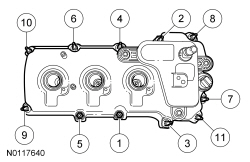
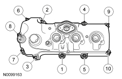
- Using a new gasket, install the LH valve cover and tighten the 10 stud
bolts.
- Tighten in the sequence shown to 10 Nm (89 lb-in).
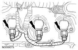
- Install 3 RH ignition coil-on-plugs and the 3 bolts.
- Tighten to 7 Nm (62 lb-in).
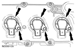
- Install 3 LH ignition coil-on-plugs and the 3 bolts.
- Tighten to 7 Nm (62 lb-in).
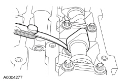
- NOTE: The cam lobe for the fuel injection pump must be at Bottom
Dead Center (BDC) for the fuel injection pump installation.
Using the crankshaft pulley bolt, turn the crankshaft until the fuel injection pump cam lobe is at BDC.
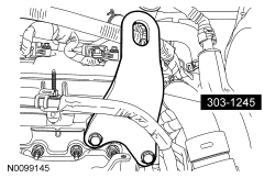
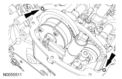
- NOTE: Valve cover is removed for clarity.
NOTE: Apply clean engine oil to the fuel injection pump mounting pedestal bore.
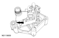
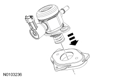
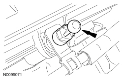
Install the fuel injection pump roller tappet.
- NOTE: Apply clean engine oil to the fuel injection pump mounting
plate seal.
Inspect the fuel injection pump mounting plate-to-valve cover gasket and replace if necessary.
- NOTE: Apply clean engine oil to the fuel injection pump mounting
plate O-ring seals.
Inspect the 2 fuel injection pump mounting plate O-ring seals and replace if necessary.
- NOTE: Apply clean engine oil to the fuel injection pump O-ring
seal.
Install the fuel injection pump on the fuel injection pump mounting plate.
- NOTE: Clean the fuel injection pump bolts and apply Thread
Sealant with PTFE to the bolts.
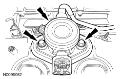
Install the fuel injection pump and the 2 bolts finger-tight.
- Tighten to 10 Nm (89 lb-in).
- Tighten an additional 45 degrees.
- NOTE: To install, apply clean engine oil to the threads of the 3
high-pressure fuel tube flare nuts.
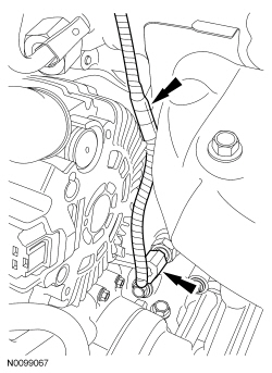
Install the high-pressure fuel tube and tighten the 3 flare nuts in the following 3 stages.
- Stage 1: Tighten to 32 Nm (24 lb-ft).
- Stage 2: Wait 10 minutes to minimize pre-stress.
- Stage 3: Tighten to 32 Nm (24 lb-ft).
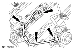
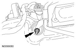
- Install the high-pressure fuel tube bracket nut.
- Tighten to 8 Nm (71 lb-in).
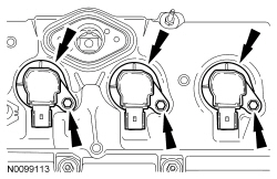
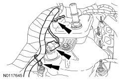
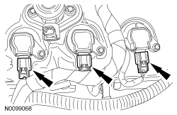
- Attach the wiring harness retainers to the RH valve cover and stud bolt.
- Connect the 3 RH ignition coil-on-plug electrical connectors.
- Connect the RH VCT solenoid electrical connector and attach the 2 wiring harness retainers.
- NOTICE: If the engine is repaired or replaced because of upper
engine failure, typically including valve or piston damage, check the intake
manifold for metal debris. If metal debris is found, install a new intake
manifold. Failure to follow these instructions can result in engine damage.
NOTE: Make sure the fuel rail wiring harnesses are routed correct.
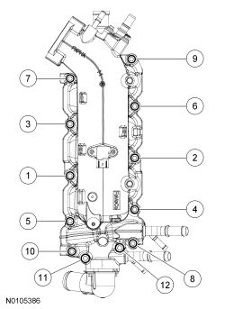
NOTE: Installing the 2 long bolts first will aid in installing the intake manifold.
Using new intake manifold, coolant crossover and thermostat housing gaskets, install the intake manifold and the 12 bolts. Tighten in the sequence shown in 2 stages.- Stage 1: Tighten to 10 Nm (89 lb-in).
- Stage 2: Tighten an additional 45 degrees.
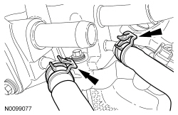
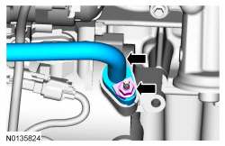
- Connect the 2 turbocharger coolant hoses to the intake manifold.
- Position the fuel tube and install the fuel tube-to-engine front cover
bracket bolt.
- Tighten to 10 Nm (89 lb-in).
- Attach the 2 wire harness-to-intake manifold retainers.
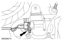
- Connect the turbocharger wastegate regulating valve electrical connector.
- Connect the Manifold Absolute Pressure (MAP)/Intake Air Temperature 2 (IAT2) sensor electrical connector.
- Connect and attach the 2 fuel injector wiring harness electrical connectors.
- Install the oil level indicator.
- Install the oil supply tube bracket on the LH valve cover stud bolt and
install the nut.
- Tighten to 8 Nm (71 lb-in).

- Attach all the wiring harness retainers to the LH valve cover and stud bolts.
- Install the engine cover mounting stud to the LH valve cover stud bolt.
- Tighten to 6 Nm (53 lb-in).
- Install the lower radiator hose to the thermostat housing.
- Connect the 3 LH ignition coil-on-plug electrical connectors.
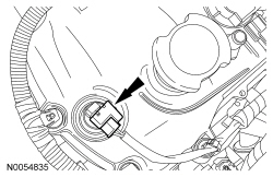
- Connect the Engine Oil Pressure (EOP) electrical connector.
- Attach the wiring harness retainer to the block.
- Connect the LH VCT solenoid electrical connector.
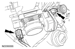
- Connect the Throttle Position (TP) and electronic Throttle Body (TB) electrical connectors.
- Connect the fuel injection pump electrical connector and install the insulated cover.
- NOTICE: The compression limiter bushing may fall out of the
mounting bracket grommet on the Charge Air Cooler (CAC) tube during service.
Make sure the bushing is in place when reinstalling the tube or damage to
the tube may occur.
Install the RH Charge Air Cooler (CAC) tube and turbocharger intake tube as an assembly and install the RH CAC tube nut to the intake manifold.
- Tighten to 6 Nm (53 lb-in).
- NOTICE: The compression limiter bushing may fall out of the
mounting bracket grommet on the turbocharger intake tube during service.
Make sure the bushing is in place when reinstalling the tube or damage to
the tube may occur.
Install the RH turbocharger intake tube to the valve cover stud bolt and install the nut.
- Tighten to 6 Nm (53 lb-in).
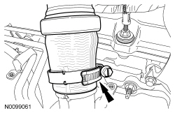
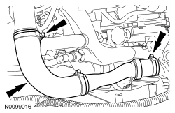
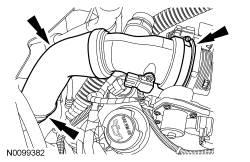
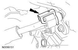
- NOTE: Align the index marks for the RH turbocharger intake pipe.
Install the RH turbocharger intake pipe to the RH turbocharger and tighten the clamp.
- Tighten to 5 Nm (44 lb-in).
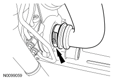
- NOTE: Align the index marks for the RH CAC tube.
Install the RH CAC tube to the RH turbocharger and tighten the clamp.
- Tighten to 5 Nm (44 lb-in).
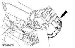
- Connect the RH turbocharger bypass valve electrical connector.
- NOTE: Align the index marks for the LH turbocharger intake tube.
Install the LH turbocharger intake tube to the LH turbocharger and tighten the clamp.
- Tighten to 5 Nm (44 lb-in).
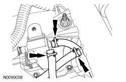
- Install the turbocharger wastegate regulating valve hoses to the turbocharger wastegate regulating valve and to the RH CAC tube.
- Connect the LH turbocharger bypass valve electrical connector.
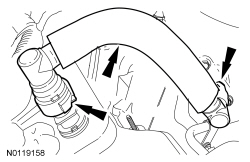
- Install the PCV tube and connect the 2 quick connect couplings. For additional information, refer to Section 310-00.
- Using a new O-ring seal and gasket seal, connect the A/C tube to the
compressor and install the nut.
- Tighten to 15 Nm (133 lb-in).
- Install the crankcase vent tube and connect the 2 quick connect couplings. For additional information, refer to Section 310-00.
- NOTE: Make sure the struts go into the knuckles when raised.
Raise the subframe and powertrain assembly into the vehicle.
- Install the engine mount and the 3 bolts.
- Tighten to 90 Nm (66 lb-ft).

- Install the 4 engine mount nuts.
- Tighten to 63 Nm (46 lb-ft).

- Install the bolt and the 3 nuts to the transaxle support insulator
bracket-to-transaxle.
- Tighten the bolt to 80 Nm (59 lb-ft).
- Tighten the nuts to 63 Nm (46 lb-ft).
- NOTE: RH shown, LH similar.
Install the 2 front subframe bolts.
- Tighten to 200 Nm (148 lb-ft).

- NOTE: RH shown, LH similar.
Position the subframe brackets and install the 4 bolts finger-tight.

- NOTE: RH shown, LH similar.
Install the 2 rear subframe bolts.
- Tighten to 150 Nm (111 lb-ft).

- NOTE: RH shown, LH similar.
Tighten the 4 subframe bracket-to-body bolts to 55 Nm (41 lb-ft).
- Remove the ratchet strap from the front of the subframe to the rear of the subframe.
- Remove the Adjustable Grip Arm and the powertrain lift table.

- NOTE: LH shown, RH similar.
Install the strut to the wheel knuckle and install the strut-to-wheel knuckle nuts and bolts.
- Tighten to 250 Nm (184 lb-ft).

- NOTE: LH shown, RH similar.
Install the brake caliper and the guide pin bolts.
- 432 mm (17 in) brakes: Tighten to 72 Nm (53 lb-ft).
- 457 mm (18 in) brakes: Tighten to 75 Nm (55 lb-ft).

- NOTICE: Do not tighten the wheel hub nut with the vehicle on
the ground. The nut must be tightened to specification before the vehicle is
lowered onto the wheels. Wheel bearing damage will occur if the wheel
bearing is loaded with the weight of the vehicle applied.
NOTE: LH shown, RH similar.
NOTE: Apply the brake to keep the halfshaft from rotating.
Using the previously removed wheel hub nut, seat the LH and RH halfshafts.- Tighten to 350 Nm (258 lb-ft).
- Remove and discard the wheel hub nuts.
- NOTICE: The wheel hub nut contains a one time locking chemical
that is activated by the heat created when it is tightened. Install and
tighten the new wheel hub nut to specification within 5 minutes of starting
it on the threads. Always install a new wheel hub nut after loosening or
when not tightened within the specified time or damage to the components can
occur.
NOTE: LH shown, RH similar.
NOTE: Apply the brake to keep the halfshaft from rotating.
Install a new wheel hub nuts.- Tighten to 350 Nm (258 lb-ft).

- NOTE: RH shown, LH similar.
Install new upper stabilizer bar link nuts.
- Tighten to 150 Nm (111 lb-ft).

- NOTE: LH shown, RH similar.
Install the wheel speed sensor and the bolt.
- Tighten to 15 Nm (133 lb-in).

- Connect the transaxle cooler tubes and install the 2 secondary latches.
- If equipped, connect the 2 PTU coolant hoses.
- If equipped, install the oil cooler hose retainer to the subframe.
- If equipped, connect the oil cooler hoses.

- Connect the lower radiator hose to the radiator.
- Attach the lower radiator hose retainer to the cooling fan and shroud.
- NOTE: Align the index marks for the LH CAC tube.
Connect the lower LH CAC tube to the LH turbocharger and tighten the clamp.
- Tighten to 5 Nm (44 lb-in).
- Using a new O-ring seal and gasket seal, install the upper A/C tube to
the A/C compressor and install the nut.
- Tighten to 15 Nm (133 lb-in).
- Position the A/C tube bracket and install bolt to the rear of the A/C
compressor.
- Tighten to 25 Nm (18 lb-ft).

- Install a new engine oil filter.
- Tighten to 5 Nm (44 lb-in) and then rotate an additional 180 degrees.

- Line up the index marks on the rear driveshaft to the index marks on
the PTU flange made during removal and install the 4 new bolts.
- Tighten to 70 Nm (52 lb-ft).
- NOTICE: Do not allow the intermediate shaft to
rotate while it is disconnected from the gear or damage to the clockspring
may occur. If there is evidence that the intermediate shaft has rotated, the
clockspring must be removed and recentered. For additional information,
refer to Section 501-20B.
Install the steering intermediate shaft onto the steering gear and install a new bolt.
- Tighten to 20 Nm (177 lb-in).
- Install the RH and LH catalytic converters. For additional information, refer to Section 309-00.
- Install the 3 scrivets in the rubber shield.

- Install the front splash shield, 3 pin-type retainers and the 7 bolts, when the coolant system or engine service is finished.

- If equipped, install the skid plate and the 10 bolts.
- Tighten to 70 Nm (52 lb-ft).

- If equipped, install the underbody shield and the 4 retainers.

- Install the front wheels and tires. For additional information, refer to Section 204-04.
- Connect the fuel supply tube. For additional information, refer to Section 310-00.
- Install the Evaporative Emission (EVAP) tube assembly and connect the quick connect coupling to the intake manifold. For additional information, refer to Section 310-00.
- Connect the EVAP valve electrical connector and attach to the intake manifold.

- Connect the EVAP tube quick connect coupling. For additional information, refer to Section 310-00.

- If equipped, attach the engine block heater harness to the radiator support wiring harness.
- Connect the upper radiator hose to the intake manifold coolant tube.

- Install the ground wire and bolt to the engine front cover.
- Tighten to 10 Nm (89 lb-in).
- Connect the 2 heater hoses to the intake manifold.

- NOTE: Align the index marks for the RH CAC tube.
Install the RH CAC tube and tighten the clamps.
- Tighten to 5 Nm (44 lb-in).
- Connect the transaxle control cable to the shift cable bracket.
- Connect the transaxle control cable to the control lever.
- Connect the quick connect coupling to the intake manifold. For additional information, refer to Section 310-00.
- Connect the battery power feed wire to the positive battery terminal and
install the nut.
- Connect the electrical connector.
- Tighten to 6 Nm (53 lb-in).
- Connect the engine wiring harness electrical connector.

- Position back the ground wire and install the bolt.
- Tighten to 6 Nm (53 lb-in).
- Install the battery tray. For additional information, refer to Section 414-01.
- NOTE: Align the index marks for the CAC outlet pipe.
Install the CAC outlet pipe and tighten the clamps.
- Tighten to 5 Nm (44 lb-in).
- Connect the Turbocharger Boost Pressure (TCBP)/Charge Air Cooler Temperature (CACT) sensor electrical connector.
- If equipped, install the noise generator. For additional information, refer to Intake Air System Components - Exploded View in Section 303-12.
- Install the engine Air Cleaner (ACL) and ACL outlet pipe. For additional information, refer to Section 303-12.
- Install the degas bottle. For additional information, refer to Section 303-03.
- Using a new O-ring seal and gasket seal, install the A/C tube and the
nut.
- Tighten to 15 Nm (133 lb-in).
- Using a new O-ring seal and gasket seal, connect the A/C tube and
install the nut.
- Tighten to 15 Nm (133 lb-in).

- Install the engine wiring harness retainer to the bulkhead.
- Slide the wiring harness in the bulkhead.
- Make sure the wiring harness retainer tab is below the bulkhead lip.

- Connect the PCM electrical connector.
- Connect the engine harness electrical connector.
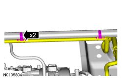
- Install the strut tower brace and the 4 nuts (2 shown).
- Tighten to 30 Nm (22 lb-ft).
- Attach the 2 brake booster vacuum hose retainers to the strut tower brace.

- Install the cowl panel grille. For additional information, refer to Section 501-02.
- Connect the LH Heated Oxygen Sensor (HO2S) electrical connector.
- Attach the HO2S connector retainer to the bracket.
- NOTICE: Do not expose the Motorcraft High Performance Engine
RTV Silicone to engine oil for at least 90 minutes after installing the
engine front cover. Failure to follow this instruction may cause oil
leakage.
Fill the engine with clean engine oil.
- Fill and bleed the cooling system. For additional information, refer to Section 303-03.
- Recharge the A/C system. For additional information, refer to Section 412-00.
- Perform the Misfire Monitor Neutral Profile Correction procedure following the on-screen instructions.
Valve Tappets
Material
NOTICE: During engine repair procedures, cleanliness is extremely important. Any foreign material, including any material created while cleaning gasket surfaces that enters the oil passages, coolant passages or the oil pan, may cause engine failure.
- NOTE: The valve tappets must be installed in their original
positions.
NOTE: Coat the valve tappets with clean engine oil prior to installation.
Install the valve tappets.
- Depending on the valve tappets being serviced, install the LH and/or the RH camshafts. For additional information, refer to Camshaft in this section.
Valve Spring, Retainer and Seal
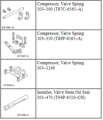
Special Tool(s)
Material
- NOTE: Lubricate the valve stem seal with clean engine oil prior
to installation.
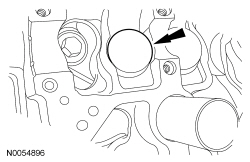
Using the Valve Stem Oil Seal Installer, install a new valve stem seal.
- Using the Valve Spring Compressors, install the valve spring, retainer and key.
- Install the valve tappets. For additional information, refer to Valve Tappets in this section.
Cylinder Head - RH
Material
NOTICE: During engine repair procedures, cleanliness is extremely important. Any foreign material, including any material created while cleaning gasket surfaces that enters the oil passages, coolant passages or the oil pan, may cause engine failure.
NOTICE: Whenever turbocharger air intake system components are removed, always cover open ports to protect from debris. It is important that no foreign material enter the system. The turbocharger compressor vanes are susceptible to damage from even small particles. All components should be inspected and cleaned, if necessary, prior to installation or reassembly.
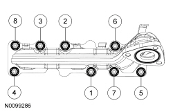
- Install a new gasket, the RH cylinder head and 8 new bolts. Tighten in
the sequence shown in 5 stages:
- Stage 1: Tighten to 20 Nm (177 lb-in).
- Stage 2: Tighten to 35 Nm (26 lb-ft).
- Stage 3: Tighten 90 degrees.
- Stage 4: Tighten 90 degrees.
- Stage 5: Tighten 45 degrees.
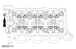
- Install the cylinder head M6 bolt.
- Tighten to 10 Nm (89 lb-in).
- NOTE: The valve tappets must be installed in their original
positions.
NOTE: Coat the valve tappets with clean engine oil prior to installation.
Install the valve tappets.

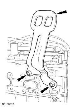
- Install the RH engine lifting eye and the 2 bolts.
- Tighten to 24 Nm (18 lb-ft).
- Install the RH secondary timing chain tensioner and the 2 bolts.
- Tighten to 10 Nm (89 lb-in).
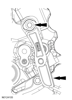
- Install the RH timing chain guide and bolt.
- Tighten to 10 Nm (89 lb-in).
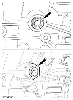
- Install the RH cylinder block drain plug or, if equipped, the block
heater.
- Tighten the cylinder block drain plug to 10 Nm (89 lb-in) plus an additional 720 degrees.
- Tighten the block heater to 40 Nm (30 lb-ft).
- If equipped, install the block heater wiring harness onto the engine.
- Connect the block heater electrical connector and install the heat shield.

- Install the LH cylinder block drain plug.
- Tighten to 16 Nm (142 lb-in) plus an additional 180 degrees.

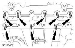
- Install 8 new RH exhaust manifold studs.
- Tighten to 12 Nm (106 lb-in).
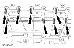
- NOTICE: Failure to tighten the exhaust manifold nuts to
specification a second time will cause the exhaust manifold to develop an
exhaust leak.
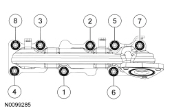
Install a new gasket, RH exhaust manifold and 8 new nuts. Tighten in 2 stages in the sequence shown:
- Stage 1: Tighten to 15 Nm (133 lb-in).
- Stage 2: Tighten to 20 Nm (177 lb-in).
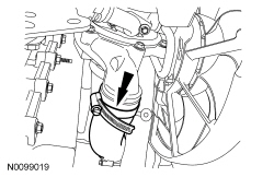
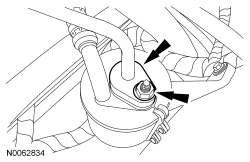
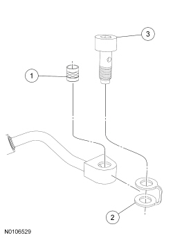
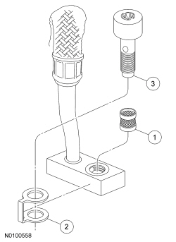
- Install the oil supply tube filter, washer and bolt.
- Install a new oil supply tube filter in the oil supply tube block.
- Slide the new washer onto the oil supply tube block.
- Instal the banjo bolt into the oil supply tube block.
- Install the RH turbocharger oil supply tube.
- Tighten the bolt to 40 Nm (30 lb-ft).
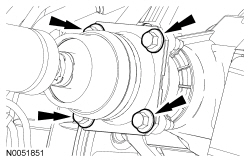
- Install a new gasket, the turbocharger and the 3 new exhaust
manifold-to-turbocharger bolts.
- Tighten to 45 Nm (33 lb-ft).
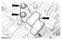
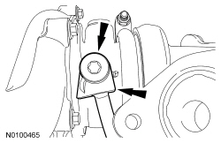
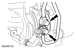
- Install the upper turbocharger-to-cylinder block bracket and the 3 bolts
and position the bracket as far clockwise as possible and tighten the bolts
in the following sequence:
- Tighten the lower bolt to 26 Nm (19 lb-ft).
- Tighten the upper bolt to 26 Nm (19 lb-ft).
- Tighten the turbocharger bolt to 19 Nm (168 lb-in).
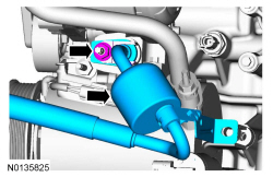
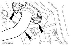
- Using 2 new sealing washers, install the 2 RH turbocharger coolant tubes
and banjo bolts.
- Tighten to 40 Nm (30 lb-ft).
- Install the coolant tube bracket-to-cylinder head bolt.
- Tighten to 10 Nm (89 lb-in).
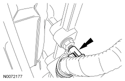
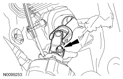
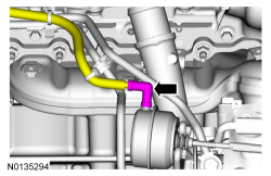
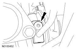
- If necessary, install the RH cylinder head turbocharger oil supply quick
connect fitting.
- Tighten to 16 Nm (142 lb-in).
- NOTE: Listen for audible click when installing the oil supply
tube into the quick connect fitting.
Install the RH oil supply tube into the quick connect fitting.
- Install the oil supply tube secondary latch.
- Install a new gasket and the RH turbocharger oil return tube and the 2
bolts.
- Tighten to 10 Nm (89 lb-in).
- NOTE: Make sure the turbocharger wastegate regulating valve hose
does not contact the exhaust manifold heat shield.
Connect the turbocharger wastegate regulating valve hose to the RH turbocharger assembly.
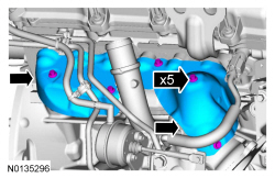
- NOTE: Make sure the heat shield does not contact the wastegate
arm.
Install the 2 upper RH exhaust manifold heat shield and the 5 bolts.
- Tighten to 12 Nm (106 lb-in).
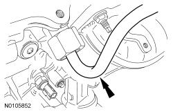
- Connect the Cylinder Head Temperature (CHT) sensor electrical connector to the rear of the RH cylinder head.
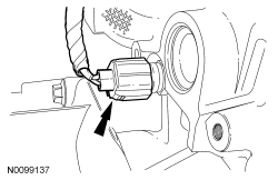
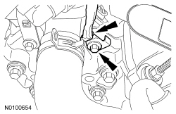
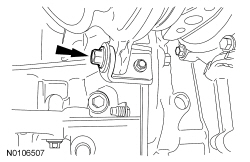
- Install the ground wire and the bolt.
- Tighten to 10 Nm (89 lb-in).
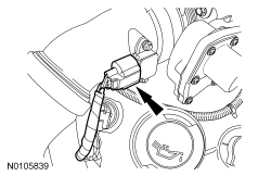
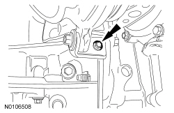
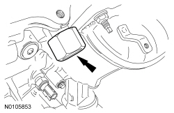
- Install the RH Camshaft Position (CMP) sensor and the bolt.
- Tighten to 10 Nm (89 lb-in).
- Connect the RH CMP sensor electrical connector.
- Install the RH camshafts. For additional information, refer to Camshaft in this section.
- Install the fuel rails. For additional information, refer to Section 303-04B.
Cylinder Head - LH
Material
NOTICE: During engine repair procedures, cleanliness is extremely important. Any foreign material, including any material created while cleaning gasket surfaces that enters the oil passages, coolant passages or the oil pan, may cause engine failure.
NOTICE: Whenever turbocharger air intake system components are removed, always cover open ports to protect from debris. It is important that no foreign material enter the system. The turbocharger compressor vanes are susceptible to damage from even small particles. All components should be inspected and cleaned, if necessary, prior to installation or reassembly.
- Install a new gasket, the LH cylinder head and 8 new bolts. Tighten in
the sequence shown in 5 stages:
- Stage 1: Tighten to 20 Nm (177 lb-in).
- Stage 2: Tighten to 35 Nm (26 lb-ft).
- Stage 3: Tighten 90 degrees.
- Stage 4: Tighten 90 degrees.
- Stage 5: Tighten 45 degrees.
- Install the cylinder head M6 bolt.
- Tighten to 10 Nm (89 lb-in).
- NOTE: The valve tappets must be installed in their original
positions.
NOTE: Coat the valve tappets with clean engine oil prior to installation.
Install the valve tappets.

- Install the LH secondary timing chain tensioner and the 2 bolts.
- Tighten to 10 Nm (89 lb-in).
- Install the upper LH primary timing chain guide and the bolt.
- Tighten to 10 Nm (89 lb-in).
- Install the RH cylinder block drain plug or, if equipped, the block
heater.
- Tighten the cylinder block drain plug to 10 Nm (89 lb-in) plus an additional 720 degrees.
- Tighten the block heater to 40 Nm (30 lb-ft).

- If equipped, install the block heater wiring harness onto the engine.
- Connect the block heater electrical connector and install the heat shield.
- Install the LH cylinder block drain plug.
- Tighten to 16 Nm (142 lb-in) plus an additional 180 degrees.
- Install 8 new LH exhaust manifold studs.
- Tighten to 12 Nm (106 lb-in).
- NOTICE: Failure to tighten the exhaust manifold nuts to
specification a second time will cause the exhaust manifold to develop an
exhaust leak.
Install a new gasket, LH exhaust manifold and turbocharger assembly and 8 new nuts. Tighten the nuts in 2 stages in the sequence shown:
- Stage 1: Tighten to 15 Nm (133 lb-in).
- Stage 2: Tighten to 20 Nm (177 lb-in).
- Install the upper turbocharger bracket-to-cylinder block and the 2
bolts.
- Do not tighten the bolts at this time.
- Install the lower turbocharger-to-cylinder block bracket and the 2
bolts.
- Do not tighten the bolts at this time.
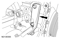
NOTICE: The next 4 steps must be performed in order or damage to the turbocharger may occur.
- Tighten the upper turbocharger bracket-to-turbocharger bolt.
- Tighten to 19 Nm (168 lb-in).
- Tighten the upper turbocharger bracket-to-cylinder block bolt.
- Tighten to 25 Nm (18 lb-ft).
- Tighten the lower turbocharger bracket-to-turbocharger bolt.
- Tighten to 19 Nm (168 lb-in).
- Tighten the lower turbocharger bracket-to-cylinder block bolt.
- Tighten to 11 Nm (97 lb-in).
- Install the oil supply tube filter, washer and bolt.
- Install a new oil supply tube filter in the oil supply tube block.
- Slide the new washer onto the oil supply tube block.
- Install the banjo bolt into the oil supply tube block.
- Install the LH turbocharger oil supply tube.
- Tighten the bolt to 40 Nm (30 lb-ft).
- Using 2 new sealing washers, install the 2 LH turbocharger coolant tubes
and the banjo bolts.
- Tighten to 40 Nm (30 lb-ft).
- If necessary, install the LH cylinder head turbocharger oil supply quick
connect fitting.
- Tighten to 16 Nm (142 lb-in).
- NOTE: Listen for audible click when installing the oil supply
tube into the quick connect fitting.
Install the LH oil supply tube into the quick connect fitting.
- Install the LH oil supply tube secondary latch.
- Install a new gasket, turbocharger oil return tube and the 2 bolts.
- Tighten to 10 Nm (89 lb-in).
- NOTE: Make sure the turbocharger wastegate regulating valve hose
does not contact the exhaust manifold heat shield.
Connect the turbocharger wastegate regulating valve hose to the LH turbocharger assembly.
- Install the LH exhaust manifold heat shield and the 3 bolts.
- Tighten to 12 Nm (106 lb-in).

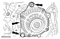
- Install the stud, generator and the nut and bolt.
- Tighten the stud to 8 Nm (71 lb-in).
- Tighten the nut and bolt to 47 Nm (35 lb-ft).
- Connect the generator electrical connector.
- Connect the generator B+ cable and install the nut.
- Tighten to 17 Nm (150 lb-in).
- Install the LH coolant tube bracket-to-cylinder head nut.
- Tighten to 10 Nm (89 lb-in).
- Attach the pin-type wire harness retainer to the rear of LH cylinder head.
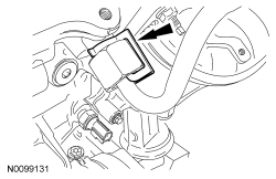
- Install the LH Camshaft Position (CMP) sensor and the bolt.
- Tighten to 10 Nm (89 lb-in).
- Connect the LH CMP sensor electrical connector.
- Install the LH camshafts. For additional information, refer to Camshaft in this section.
- Install the fuel rails. For additional information, refer to Section 303-04B.
 Assembly
Engine
Special Tool(s)
Material
Engine Upper
Engine Upper - LH Cylinder Head
Engine Upper - RH Cylinder Head
Engine Front
Timing Drive Components
Lower Engine Block (View 1)
Lowe ...

Other materials:
Brake System - General Information
SPECIFICATIONS
Material
General Specifications
Torque Specifications
DIAGNOSIS AND TESTING
Principles of Operation
Brake System
Applying the brake pedal uses lever action to push a rod into the brake
booster, which through the use of vacuum, boosts the force of the rod and then
transmits this f ...
Removal and Installation
Roof Opening Panel - Exploded View
NOTE: The roof opening panel motor must be initialized when repairs
are carried out on any part of the roof opening panel system, including:
whenever the roof opening panel motor has been removed from the roof opening
panel system, the roof opening panel gl ...
Removal and Installation
Seat - Front
NOTE: Refer to the installation steps for tightening sequence and
torque specification.
NOTE: Passenger seat shown, driver seat similar.
Removal
NOTE: The Supplemental Restraint System (SRS) must be fully
operational and free of faults before releasing the vehicle to ...
