Brake Shift Interlock Override - Floor Shift
NOTE: If it is necessary to use the override procedure to move the selector lever out of the PARK position, it is possible that a fuse has blown. GO to Pinpoint Test A.
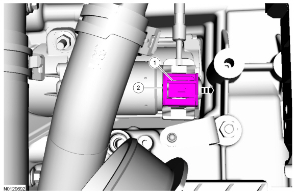
This vehicle is equipped with a brake shift interlock feature that prevents the selector lever from being moved out of PARK when the ignition is in the ON position until the brake pedal is applied.
If the selector lever cannot be moved out of the PARK position when the ignition is in the ON position and the brake pedal is applied:
- Apply the parking brake. Turn the ignition key to the off position and remove the key.
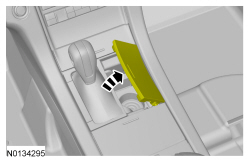
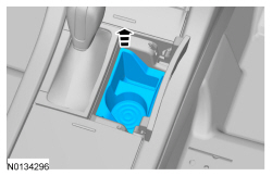
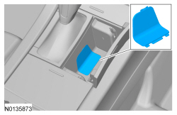
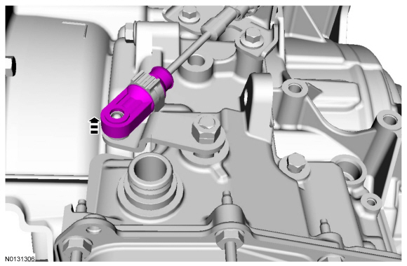
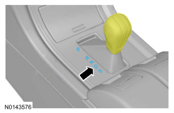
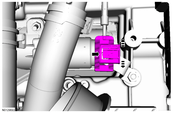
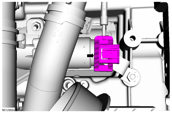
- Push the brake shift interlock override mechanism on the selector lever forward, apply the brake, press the button on the selector lever and move the selector lever into NEUTRAL.
- Start the vehicle.
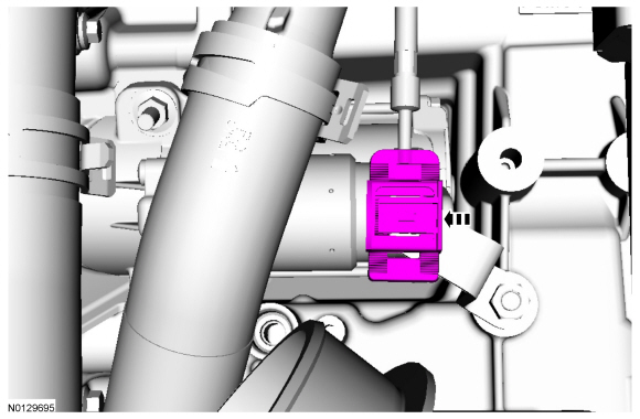
- For assembly, reverse the procedure.
Selector Lever Cable Adjustment - 6F35

-
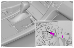
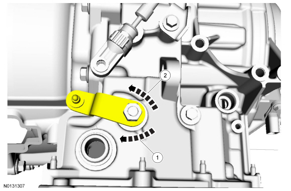
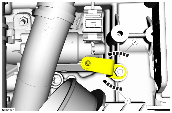
- Rotate the manual control lever clockwise until it stops.
- Rotate the manual control lever counterclockwise 1 detent.
-
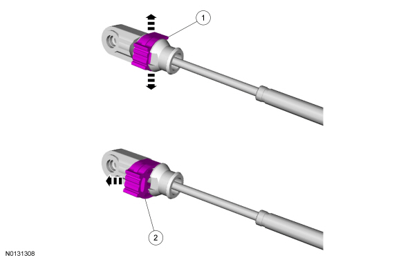
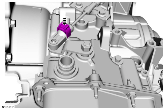
- Carefully pry outward the adjuster lock tabs.
- While holding the adjuster lock tabs outward, slide the lock to unlock the selector lever cable.
- NOTICE: To prevent selector lever cable damage, do not apply
force to the selector lever cable between the manual control lever and the
selector lever cable bracket.
NOTE: Make sure that the selector lever cable end is correctly installed onto the manual control lever ball stud by pulling back on the selector lever cable end.
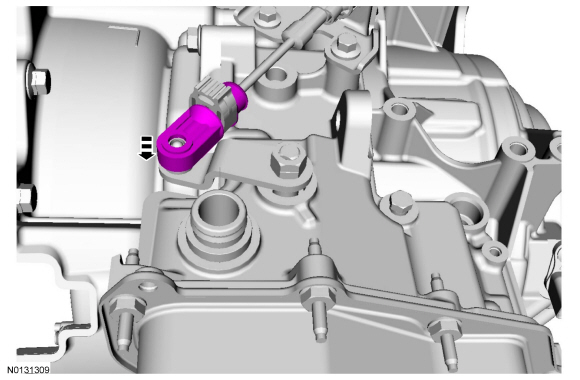
- NOTE: After locking the adjuster, pull back on the adjuster to make sure it is securely installed.
- Verify that the vehicle starts in PARK and NEUTRAL only and that the reverse lamps illuminate in REVERSE.
Selector Lever Cable Adjustment - 6F50/6F55
- Remove the ACL and outlet pipe. Refer to Section 303-12.
-
- Rotate the manual control lever clockwise until it stops.
- Rotate the manual control lever counterclockwise one detent.
-
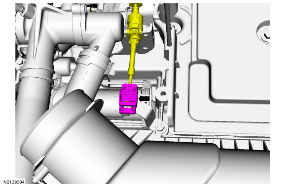
- Gently pry the latch up.
- Push the lock tab to slide it over.
- NOTICE: To prevent selector lever cable damage, do not apply
force to the selector lever cable between the manual control lever and the
selector lever cable bracket.
NOTE: Make sure that the selector lever cable end is correctly installed onto the manual control lever ball stud by pulling back on the selector lever cable end.
- NOTE: After locking the adjuster, pull back on the adjuster to make sure it is securely installed.
- Install the ACL and outlet pipe. Refer to Section 303-12.
- Verify that the vehicle starts in PARK and NEUTRAL only and that the reverse lamps illuminate in REVERSE.
 Diagnosis and Testing
External Controls
Inspection and Verification
Verify the customer concern by operating the system.
Visually inspect for obvious signs of mechanical or electrical damage.
If the concern is not ...
 Removal and Installation
Selector Lever Cable - Floor Shift
Removal
All vehicles
With the vehicle in NEUTRAL, position it on a hoist. Refer to Section
100-02.
NOTICE: Failure to use a piece of c ...
Other materials:
Supplementary Restraints System
PRINCIPLES OF OPERATION
WARNING: Airbags do not inflate slowly or gently, and the risk
of injury from a deploying airbag is the greatest close to the trim
covering the airbag module.
WARNING: All occupants of your vehicle, including the driver,
should always properly wear their safety belts, ev ...
Diagnosis and Testing
Seating
Special Tool(s)
Medium Speed Controller Area Network (MS-CAN)
This vehicle utilizes a communication system called a Medium Speed Controller
Area Network (MS-CAN). When diagnosing the memory seat, heated seats or climate
controlled seats, use a Vehicle Communication Module (VCM) and Integr ...
Fuel Charging and Controls - 3.5L GTDI
SPECIFICATIONS
Material
Torque Specifications
a Refer to the procedure in this section.
DESCRIPTION AND OPERATION
Fuel Charging and Controls
3.5L Gasoline Turbocharged Direct Injection (GTDI)
WARNING: Do
not smoke, carry lighted tobacco or have an open flame of any type when working
on or n ...
