Selector Lever Cable - Floor Shift
Removal
All vehicles
- With the vehicle in NEUTRAL, position it on a hoist. Refer to Section 100-02.

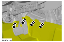
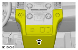
- NOTICE: Failure to use a piece of cardboard between the LH center console lower trim panel and the center console can result in damage to the side of the center console.
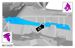


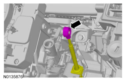
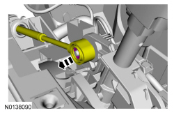
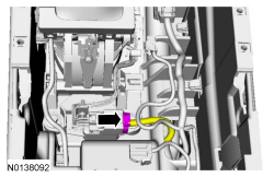
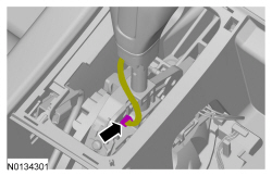
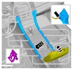
- NOTE: Note the routing of the selector lever cable under the heater housing for assembly.
6F50/6F55
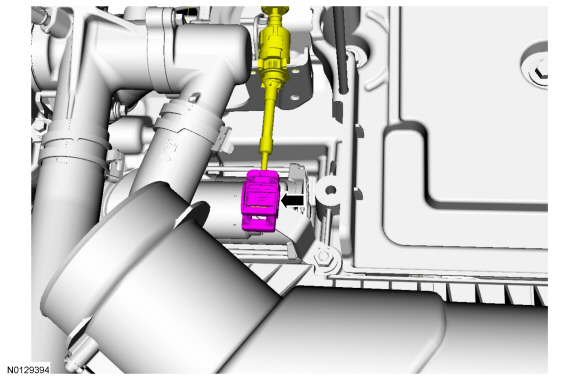
- Remove the Air Cleaner (ACL) and outlet pipe. Refer to Section 303-12.

6F35
All vehicles

Installation
All vehicles
-
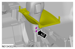
- Tighten to 7 Nm (62 lb-in).
- NOTE: Route the selector lever cable under the heater housing as noted during removal.
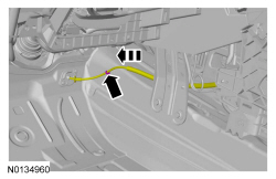
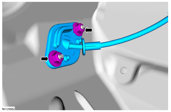
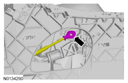
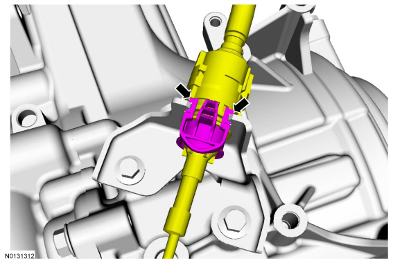
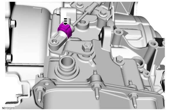
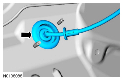
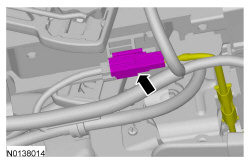
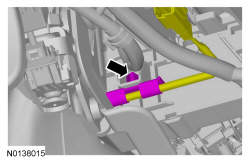
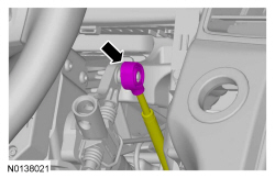
- NOTE: When installing the selector lever cable, make sure that the selector lever cable locking tabs are locked in place. Press the selector lever cable into the selector lever housing and listen for the selector lever cable retainer to click in place. Pull back on the selector lever cable to make sure that the selector lever is locked into the selector lever housing.
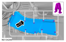

- NOTICE: Failure to use a piece of cardboard between the LH center console lower trim panel and the center console can result in damage to the side of the center console.


6F35
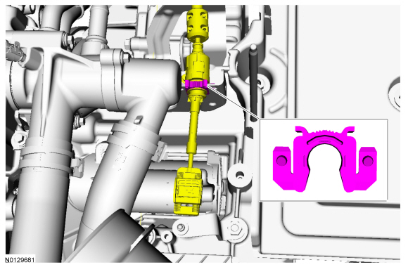
- NOTE: When installing the selector lever cable, make sure that both selector lever cable locking tabs are locked in place. Press the selector lever cable into the selector lever cable bracket and listen for the selector lever cable retainer to click in place. Pull back on the selector lever cable to make sure that the selector lever is locked into the selector lever cable bracket.
-
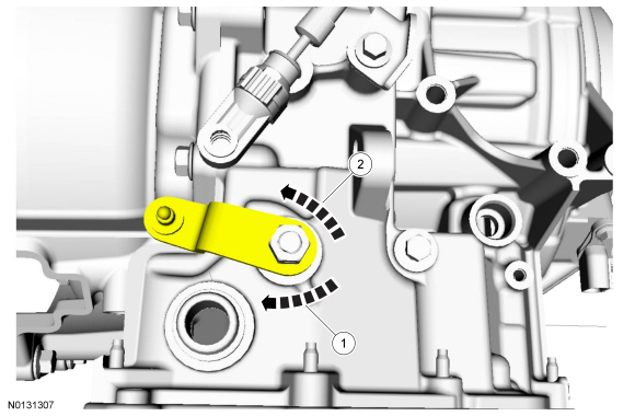
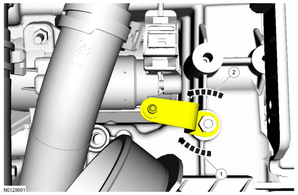
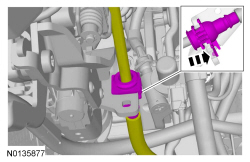
- Rotate the manual control lever clockwise until it stops.
- Rotate the manual control lever counterclockwise 1 detent.
-
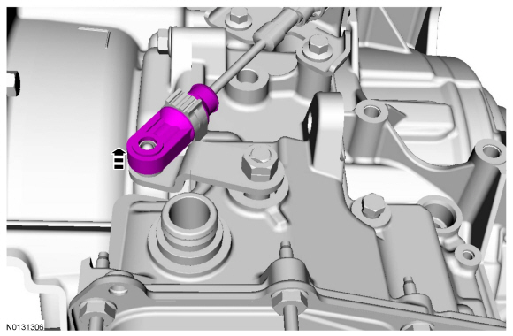
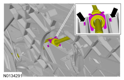
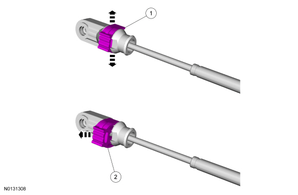
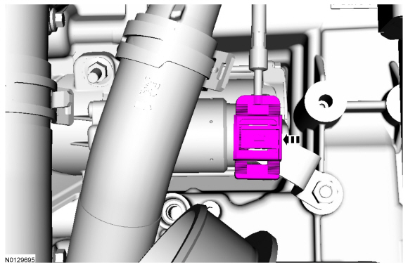
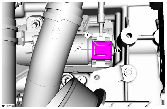
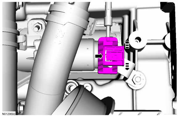
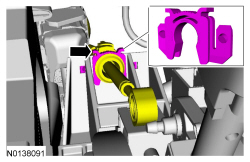
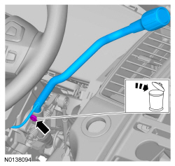
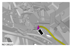
- Carefully pry outward the adjuster lock tabs.
- While holding the adjuster lock tabs outward, slide the lock to unlock the selector lever cable.
- NOTICE: To prevent selector lever cable damage, do not apply
force to the selector lever cable between the manual control lever and the
selector lever cable bracket.
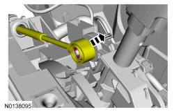
NOTE: Make sure that the selector lever cable end is correctly installed onto the manual control lever ball stud by pulling back on the selector lever cable end.
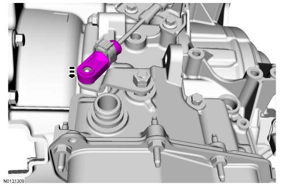
- NOTE: After locking the adjuster, pull back on the adjuster to make sure it is securely installed.
6F50/6F55
- NOTICE: To prevent selector lever cable damage, do not apply
force to the selector lever cable between the manual control lever and the
selector lever cable bracket.
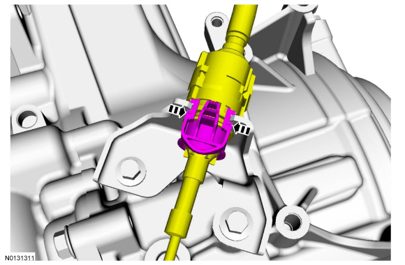
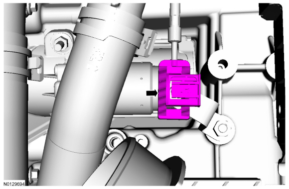
NOTE: When installing the selector lever cable, make sure that the selector lever cable locking tabs are locked in place. Press the selector lever cable into the selector lever cable bracket and listen for the selector lever cable retainer to click in place. Pull back on the selector lever cable to make sure that the selector lever is locked into the selector lever cable bracket.
-
- Rotate the manual control lever clockwise until it stops.
- Rotate the manual control lever counterclockwise one detent.
-
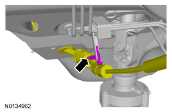
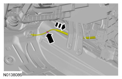
- Gently pry the latch up.
- Push the lock tab to slide it over.


- NOTICE: To prevent selector lever cable damage, do not apply
force to the selector lever cable between the manual control lever and the
selector lever cable bracket.
NOTE: Make sure that the selector lever cable end is correctly installed onto the manual control lever ball stud by pulling back on the selector lever cable end.

- NOTE: After locking the adjuster, pull back on the adjuster to make sure it is securely installed.
- Install the Air Cleaner (ACL) and outlet pipe. Refer to Section 303-12.
All vehicles
- Verify that the vehicle starts in PARK and NEUTRAL only and that the reverse lamps illuminate in REVERSE.
Selector Lever Cable - Column Shift
Removal
- With the vehicle in NEUTRAL, position it on a hoist. Refer to Section 100-02.
- Remove the steering column shrouds. Refer to Section 211-04.

- Remove the ACL and outlet pipe. Refer to Section 303-12.


Installation


- Install the steering column shrouds. Refer to Section 211-04.

- NOTICE: To prevent selector lever cable damage, do not apply
force to the selector lever cable between the manual control lever and the
selector lever cable bracket.
NOTE: When installing the selector lever cable, make sure that the selector lever cable locking tabs are locked in place. Press the selector lever cable into the selector lever cable bracket and listen for the selector lever cable retainer to click in place. Pull back on the selector lever cable to make sure that the selector lever is locked into the selector lever cable bracket.

- Place the selector lever in DRIVE.
-
- Rotate the manual control lever clockwise until it stops.
- Rotate the manual control lever counterclockwise one detent.

-
- Gently pry the latch up.
- Push the lock tab to slide it over.
- NOTICE: To prevent selector lever cable damage, do not apply
force to the selector lever cable between the manual control lever and the
selector lever cable bracket.
NOTE: Make sure that the selector lever cable end is correctly installed onto the manual control lever ball stud by pulling back on the selector lever cable end.
- NOTE: After locking the adjuster, pull back on the adjuster to make sure it is securely installed.

- Install the ACL and outlet pipe. Refer to Section 303-12
- Verify that the vehicle starts in PARK and NEUTRAL only and that the reverse lamps illuminate in REVERSE.
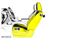
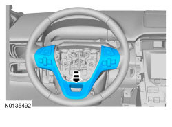
Selector Lever - Paddle Shift
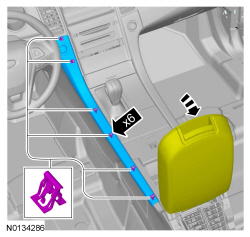
- Remove the driver air bag module. For additional information, refer to Section 501-20B.
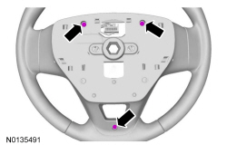
- On both sides.
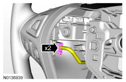
-
- To install, tighten to 5 Nm (44 lb-in).
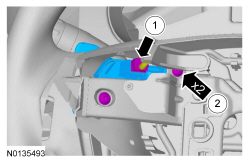
- To install, reverse the removal procedure.
Selector Lever - Floor Shift
Removal
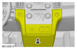
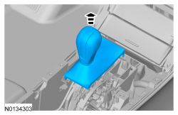
- Remove the selector lever bezel. Refer to Selector Lever Bezel - Floor Shift.


Installation
-
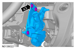
- Tighten to 12 Nm (106 lb-in).

- NOTE: When installing the selector lever cable, make sure that the selector lever cable locking tabs are locked in place. Press the selector lever cable into the selector lever housing and listen for the selector lever cable retainer to click in place. Pull back on the selector lever cable to make sure that the selector lever is locked into the selector lever housing.
- Install the selector lever bezel. Refer to Selector Lever Bezel - Floor Shift.
- Adjust the selector lever cable when a new selector lever is installed. Refer to Selector Lever Cable Adjustment - 6F35 or Selector Lever Cable Adjustment - 6F50/6F55.
Selector Lever - Column Shift
Removal
- Remove the steering column shrouds. Refer to Section 211-04.
-
- To install, tighten to 18 Nm (159 lb-in).
Installation
- To install reverse the removal procedure.
Selector Lever Knob - Floor Shift
Removal
All vehicles
- Remove the selector lever bezel. Refer to Selector Lever Bezel - Floor Shift.
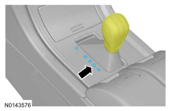
Vehicles equipped with SelectShift
All Vehicles
Installation
- To install, reverse the removal procedure.
Selector Lever Bezel - Floor Shift
Removal


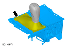
- NOTE: Selector lever shown out of vehicle for clarity.

Installation
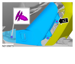
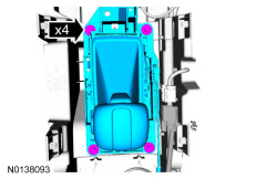
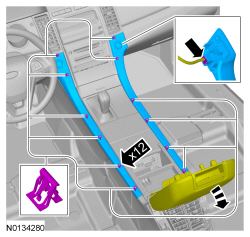
- Install the selector lever bezel and position the selector lever boot on the selector lever bezel.
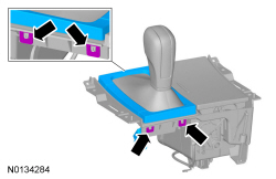
- Tilt the selector lever up and connect the selector lever bezel.

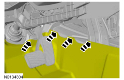
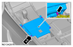
- Install the 4 selector lever bezel screws.
Selector Lever Mechanism - Column Shift
Removal and Installation
- NOTE: To access the top selector lever mechanism bolts, position
the selector lever in NEUTRAL before removing the selector lever.
Remove the selector lever. Refer to Selector Lever - Column Shift.
-
- To install, tighten to 10 Nm (89 lb-in).
- To install, reverse the removal procedure.
- Adjust the selector lever cable when a new selector lever mechanism is installed. Refer to Selector Lever Cable Adjustment - 6F35 or Selector Lever Cable Adjustment - 6F50/6F55.
 General Procedures
Brake Shift Interlock Override - Floor Shift
NOTE: If it is necessary to use the override procedure to move
the selector lever out of the PARK position, it is possible that a fuse has
blown.&nb ...

Other materials:
Safety precautions
WARNING: Do not overfill the fuel tank. The pressure in an
overfilled tank may cause leakage and lead to fuel spray and fire.
WARNING: The fuel system may be under pressure. If you hear
a hissing sound near the fuel filler inlet, do not refuel until the
sound stops. Otherwise, fuel may spray out ...
Removal and Installation
Hood Latch
Removal and Installation
Remove the upper radiator sight shield.
Remove the 8 screws.
Remove the 4 bolts.
Remove the 2 pin-type retainers.
NOTE: Mark the position of the hood latch prior to removing the
hood latch bolts.Remove the 2 bolts and position t ...
Traction Control
PRINCIPLES OF OPERATION
The traction control system helps avoid drive wheel spin and loss of
traction.
If your vehicle begins to slide, the system applies the brakes to individual
wheels and, when needed, reduces engine power at the same time. If the
wheels spin when accelerating on slippery ...
